PROJECT MEMBERS John Hickey Kaitlin DeHerrera
Jared Christner Ryan Edwards
Mechanical Engineering Department
California Polytechnic State University, San Luis Obispo June 9, 2020
SPONSOR Myles Wittman Company: Outdoor Research
Abstract
Spring loaded camming devices or “cams” are used in traditional rock climbing as a means of active fall protection. Climbers place cams in cracks and fissures in the rock wall. The cam’s lobes press against the walls, locking it in place, anchoring the climber in case of a fall.
Currently, there is a lack of large cams on the market. Only two small companies produce cams that are usable in cracks 6.5 inches wide and larger, however their designs are either too heavy and/or lack features to be comfortable. We are a group of mechanical engineering students at Cal Poly San Luis Obispo, and at the beginning of this project we aimed to design, manufacture, and test a large active fall protection device that improves on the currently available designs. Primarily, we wanted our design to be lightweight, strong, and have a semi-flexible stem. Due to the COVID-19 outbreak and campus closure in March 2020, we were forced to adapt and modify our goals to be achievable while we continued to work remotely. Since we did have access to Cal Poly facilities, we built a single camming device instead of the planned ten and were unable to tensile test the final cam. Even so, we feel that the testing results obtained from this prototype will be able to guide future iterations. The Final Design Report summarizes the background and market research we conducted, explains our objectives of the project, outlines and justifies the design concept, describes our final prototype and how we manufactured it, and details the formal testing procedure required to validate our calculations as well as provides recommendations for moving forward. We found that the prototype met all specifications but for the weight limit. It costs less than $130 per cam to manufacture, is usable in the targeted 6-9 inch range of rock crack widths, and has a flexible stem as requested by the climbing
Table of Contents
1 Introduction ... - 1 -
2 Background ... - 3 -
2.1 Summary of Meeting with Sponsor ... - 3 -
2.2 Summary of Interviewing Climbing Colleagues ... - 3 -
2.3 Survey to Target Market ... - 3 -
2.4 Discussion of Existing Designs ... - 4 -
2.5 Relevant Technical Literature ... - 8 -
3 Objectives ... - 9 -
3.1 Problem Statement ... - 9 -
3.2 Boundary Diagram ... - 9 -
3.3 Wants and Needs ... - 10 -
3.4 Design Specifications ... - 11 -
3.5 Quality Function Development Process ... - 11 -
4 Concept Design ... - 12 -
4.1 Ideation Process ... - 13 -
4.2 Initial Concept ... - 13 -
4.3 Concept Selection Process ... - 15 -
4.4 Detailed Description of Selected Concept ... - 16 -
4.5 Preliminary Analysis ... - 17 -
4.6 Risks, Challenges, & Unknowns ... - 18 -
5 Final Design ... - 19 -
5.1 Lobe Design and Analysis ... - 21 -
5.2 Carriage Design and Analysis ... - 25 -
5.3 Axle Design and Analysis ... - 27 -
5.4 Stem Design and Analysis ... - 29 -
5.5 Trigger Design and Analysis ... - 29 -
5.6 Cost Analysis by Component ... - 31 -
5.7 Safety Analysis ... - 33 -
6.2 Carriage ... - 34 -
6.3 Stem ... - 34 -
6.4 Axles ... - 35 -
6.5 Lobe Soft Jaws... - 36 -
6.6 Lobes ... - 36 -
6.7 Springs ... - 37 -
6.8 Axle Linkage ... - 38 -
6.9 Triggers ... - 39 -
6.10 Trigger Cord ... - 39 -
6.11 Nylon Sling ... - 39 -
6.12 Assembly: ... - 39 -
6.13 Challenges and Recommendations ... - 42 -
7 Design Verification ... - 42 -
7.1 Completed Tests and Results ... - 43 -
7.2 Incomplete Tests ... - 46 -
8 Project Management ... - 48 -
8.1 Overall Design Process ... - 48 -
8.2 Unique Processes Used ... - 49 -
9 Conclusion ... - 50 -
9.1 Next Steps:... - 50 -
9.2 Reflection ... - 51 -
References ... - 52 -
Appendix K: Drawing Package ... W Appendix L: Design Verification Plan ... MM Appendix M: Test Procedures ... NN Appendix N: Gantt Chart and Gantt List ... SS
List of Figures
Figure 1. A typical spring-loaded camming device being used to anchor this climber to the rock in case
they lose their grip. [1] ... 1
-Figure 2. Graphical summary of the specification priorities of the target audience. ... 4
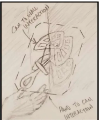
-Figure 3. Boundary diagram which shows the scope of the project. ... 9
-Figure 4. Preliminary CAD model of our chosen concept direction. ... 12
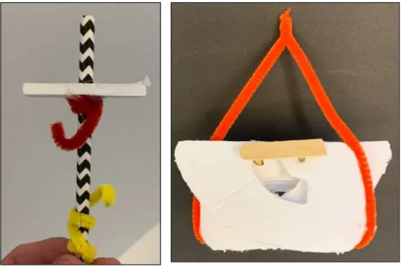
-Figure 5. Two prototypes built from craft supplies. We built the prototypes based upon ideas from the ideation sessions. ... 13
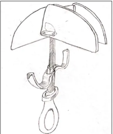
-Figure 6. Drawing of Design A, which features a butterfly trigger, a pressed U stem, and a rotating collar lock. ... 16
-Figure 7. Concept Prototype for butterfly trigger mechanism ... 17
-Figure 8. Calculation used to find the reaction forces acting on the cam lobes [27] ... 18
-Figure 9. Strength of wire rope based on diameter [28] ... 18
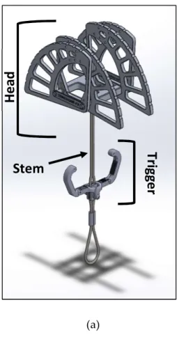
-Figure 10 (a). Final Design Assembly Note: Trigger Cords not Pictured ... 20
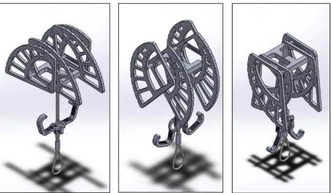
-Figure 11. From Left to right: unactuated, partially actuated, fully actuated ... 21
-Figure 12. Final Lobe Design... 22
-Figure 13: Lobe Abaqus Model ... 23
-Figure 14: Von Mises Plot (Global Mesh Size: 1.5 mm, Linear Hexahedral Elements) ... 23
-Figure 15: First Linear Buckling Mode ... 24
-Figure 16: Lobe Thickness Optimization Plot ... 25
-Figure 17. Carriage with Axles ... 26
-Figure 18: Carriage FEA Model Showing Load and Boundary Conditions ... 26
-Figure 19: FEA of Carriage with Reduced Center ... 27
-Figure 20. Axle Linkage and Snap Rings ... 28
-Figure 21: Von Mises Stress FEA of Carriage, Axles, and Axle Link ... 28
-Figure 22. Three swage carriage connection ... 29
-Figure 23. Trigger Assembly ... 30
-Figure 24. Exploded Trigger Assembly ... 30
-Figure 25. The carriage component for the final cam design. ... 34
-Figure 28. One of the finished lobes. We obtained this shape through extensive FEA. ... 37
-Figure 29. The finished torsional springs. ... 38
-Figure 30. Finished axle linkage. ... 38
-Figure 31. Finished trigger handle. ... 39
-Figure 32. Sling attached to the thumb loop. ... 40
-Figure 33. Crimped swage above the carriage, which secures it to the stem. ... 41
-Figure 34. Lobes secured to the axles and carriage subassembly using snap rings. ... 41
-Figure 35. Fully assembled camming device. ... 42
-Figure 36. Weighing the cam. The weight is 1135 g. ... 43
-Figure 37. Using a ruler to measure the distance between the lobes’ contact points when it is (a) unactuated and (b) 100% actuated. ... 44
-Figure 38. Using a weight to simulate a bend test of the stem. (a) The cam in the test jig without a weight attached. (b) The cam’s stem was able to bend around a 90 degree corner without sustaining permanent deformation. ... 45
-Figure 39. Testing that the stem does not buckle during the actuation of the cam. ... 46
-Figure 40. Black Diamond Pull-testing a Cam in Umbrella Mode [28] ... 47
-Figure 41. Tensile testing equipment. (a) Tensile Test Fixture, (b) Sample Cam within Test Fixture, - 48 -
List of Tables
Table 1. Current products on the market. ... - 5 -Table 2. Table of patent search results ... - 6 -
Table 3. Industry Standards ... - 7 -
Table 4. Customer Wants and Needs. ... - 10 -
Table 5. Specifications Table ... - 11 -
Table 6. Morphological Table Showing Design A Configuration ... - 14 -
Table 7. Weighted Decision Matrix ... - 15 -
1
Introduction
Traditional (trad) climbing is a style of rock climbing in which the climber carries and places protective equipment to secure them from hitting the ground, and then removes all gear when they complete the route. These types of climbs are done outdoors on natural rock walls, where no preset bolts exist. We focused on active protection devices, which must be actuated by the user. Active devices are placed into cracks and holes in the rock. The end in the crack expands to press against the walls of the rock, while the other end clips to the climber's rope. An example of an active device is a spring-loaded camming device (cam), shown in Error! Reference source not found.., which consists of multiple lobes that rotate inwards while the device is being placed into the crack and expand to the size of the crack once the climber releases the trigger.
Figure 1. A typical spring-loaded camming device being used to anchor this climber to the rock in case they lose their grip. [1]
cam that can be used for large cracks. This project is being externally sponsored by Myles Wittman, a Production Manager at Outdoor Research, who is also a passionate rock climber. The Final Design Review is divided into eight sections:
Background
In the Background section, we summarize the research we conducted during in the ideation and initial design phase. This includes insights from interviews with rock climbers, an analysis of current products and patents, a collection of technical articles detailing the different aspects of spring-loaded cam design and testing, and rock-climbing industry standards that our design must comply to.
Objectives
Here we state and detail the goals and deliverables of the project. We address the specific problem we aim to solve, the wants and needs of the climbing community, the Quality Function Diagram (QFD) process, as well as our design specifications and how we are measuring them.
Concept Design
In the Concept Design section we detail our final design concept and the controlled convergence strategies and thought processes we used to formulate it.
Final Design
Here we walk through our final design description and analysis by component. This section also includes cost analysis for our verification prototype.
Manufacturing
In the Manufacturing section we outline the machining and assembly processes of the subassemblies, the total cam assembly, and provides our recommendations.
Design Verification
In the Design Verification section we have detailed all testing procedures that are necessary to verify functionality of the cam.
Project Management
In the Project Management section we discuss the path taken to complete the project. It also highlights unique manufacturing and prototyping methods used and lists all purchases made. Conclusions
2
Background
The background section summarizes the market research we conducted. It is important to thoroughly understand the desires of rock climbers, our target audience, for their protective equipment. Therefore, we interviewed our rock climbing peers and more experienced trad climbers to determine their opinions of the large cams currently available. We also gathered information on company patents that are potentially useful as well as related research other engineers have completed.
2.1
Summary of Meeting with SponsorMr. Wittman is a Cal Poly Mechanical Engineering alum working in Los Angeles at Outdoor Research. He is very passionate about climbing and has experience in placing large gear when trad climbing. He also owns a lot of active protection gear and uses it frequently.
During our first meeting with Mr. Wittman, we agreed that the current market lacks ideal pieces on the market to be used for protection against large cracks. He requested that we build as many initial prototypes of the cam as possible, and also provided useful feedback for what he likes about the gear that he owns; he prefers for his gear to have adjustable webbing that he can clench between his teeth while he adjusts his holding position on the wall, to have a locking mechanism so that the piece is not fully splayed out while he carries it up the pitch, be as lightweight as possible while providing a sturdy hold, and to have a good friction pattern machined on the outside of the metal lobes [2].
2.2
Summary of Interviewing Climbing ColleaguesTo better understand the wants and needs of a range of climbers, we interviewed a handful of friends who frequently use traditional climbing gear. The information that we gathered from these interviews was very interesting and may lead to a shift in the focus of our design. One design consideration that we considered to be critical was the stem flexibility; however, the climbers that we interviewed considered the flexible stem to be non-critical. They instead focused on ergonomics, a locking mechanism that can be locked and unlocked with one hand, overall size, weight, and the cams usable range [3], [4], [5], [6], [7]. To better understand our customer wants and needs we will conduct a survey and a series of focus groups throughout our product development. This will help us narrow down our design considerations and develop a better product.
2.3
Survey to Target Marketother form of climbing. The range of experience of our audience was very wide, varying from one year to twenty years. We asked the participants what mattered most, to them, when
selecting active protection. As can be seen graphically in Figure 2, most people would prioritize strength before weight when purchasing a piece and would prioritize holding power over durability.
Figure 2. Graphical summary of the specification priorities of the target audience.
Multiple people mentioned that it is crucial to have a camming piece that is easy to use because the climbers experience extreme fatigue in their arm muscles during long routes. In general, smooth deployment and quick insertion into cracks makes for a good device.
2.4
Discussion of Existing DesignsTo understand the current market environment and advances in the technology of
Company
Name Product Description Picture Reference
Valley
Giant VG9
Large camming device with flexible, u-stem and single-axle
Rated to 18kN
Range of 6-9 in.
Weighs 920 grams.
[8]
Merlin 8
Large camming device with rigid, single stem and double-axle design.
Rated to 9 kN.
Range of 6-9 in.
Weighs 570 grams.
[9] Black Diamond C4 Camalot #6
Large camming device with flexible single stem and single-axle design.
Rated to 14 kN.
Range of 4.5-7.7 in.
Weighs 530 grams.
[10]
Trango Big Bro #3
Large expandable tube chock
Rated to 12 kN.
Range of 7.5-12 in.
Weighs 338 grams.
[11]
Kong Gipsy #6
Large triangular folding cam
Rated to 18 kN.
Range of 4-8 in.
Weighs 488 grams.
Table 2. Table of patent search results Patent
Name Number Patent Key Characteristics Drawing Reference
Camming Devices
US 6,679,466
B2
4 lobe Wild Country Cam
Double-axle cam with slots to prevent over rotation
Stem can rotate about the lobes of the cam
[13] Protection device for use in climbing 11152652. 1
4 lobe DMM Cam
Double-axle with bias springs to keep cam in extended position
Steel cable stem wrapped in plastic sleeve
Concave plastic trigger activation bar [14] Camming Device Stem US 9,302,154 B2
Black Diamond camming device
Steel cable stem
Retraction sleeve nested within independent sleeves to protect from wear
Also allow retractions even when under an outside load. [15] Active Camming Device Surface US 7,275,726 B2
Black Diamond Camming surface
Both concave and
convex faces of the lobes
Non flat camming surfaces increase stability
Provide increased connection points with the rock
Name Number Key Characteristics Drawing e
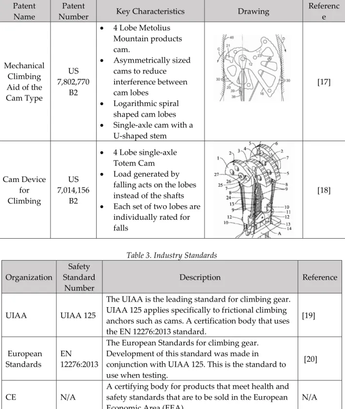
Mechanical Climbing Aid of the Cam Type
US 7,802,770
B2
4 Lobe Metolius Mountain products cam.
Asymmetrically sized cams to reduce interference between cam lobes
Logarithmic spiral shaped cam lobes
Single-axle cam with a U-shaped stem [17] Cam Device for Climbing US 7,014,156 B2
4 Lobe single-axle Totem Cam
Load generated by falling acts on the lobes instead of the shafts
Each set of two lobes are individually rated for falls
[18]
Table 3. Industry Standards
Organization Standard Safety
Number Description Reference
UIAA UIAA 125
The UIAA is the leading standard for climbing gear. UIAA 125 applies specifically to frictional climbing anchors such as cams. A certification body that uses the EN 12276:2013 standard.
[19]
European
Standards EN 12276:2013
The European Standards for climbing gear. Development of this standard was made in
conjunction with UIAA 125. This is the standard to use when testing.
[20]
CE N/A A certifying body for products that meet health and safety standards that are to be sold in the European Economic Area (EEA).
2.5
Relevant Technical LiteratureSince rock climbing is not a widespread sport, and crack climbing is even more niche, it was somewhat difficult to find technical articles directly related to spring loaded camming devices. When we were unable to find articles related to rock climbing and camming devises, we attempted to find analogous research in other engineering fields. We focused on four areas of interest: methods of testing the strength of the cam, friction analysis, methods to inhibit buckling in the stem, and the mechanics of spring-loaded camming devices.
Cam Strength Testing
The Safety of Rock Climbing Protection Devices Under Falling Loads describes the method that a team from the University of Bath used to test the strength of climbing anchor nuts under falling loads [21]. The team set up a testing rig comprising of an anchor bolt held up by support jaws and a weight which drops using a release mechanism. A load cell connects the weight and the anchor and monitors the force experienced by the anchor bolt during the drop process. The research team tested multiple weights, fall factors (the ratio between the rope length and the fall height), whether consecutive drops influence the anchor nut’s strength, as well static loading tests using an Instron tensile testing machine. They found that the anchor nuts often failed just beyond their rated loads and failed by either the steel rope ripping or the upper wall shearing. Testing of Rock Climbing Anchors discusses the current faults in the testing of chemically-bonded rock climbing anchors in soft rock [22]. In accordance the European Standard EN959 the current method is setting an anchor within a concrete block, fixing the block in place, and loading the anchor in both shear and in tension. The authors argue that the concrete does not act like the rock found on most outdoor climbing walls and the current standards are geared towards mechanical anchors, not chemically bonded anchors. They suggest creating cylindrical concrete tubes with imbedded rock. The anchors are set in the center of the rock. The researchers found the results more realistic to previous field tests.
Friction Analysis
Hughes Gauge: a new method for measuring coefficient of friction aims to improve on current
methods of measuring friction, such as the drag sled [23]. The problem with the drag sled is that the towing force will never be in co-planar with the friction, causing a moment and changing the force distribution in the contact patch. Instead, Hughes intends to correct this shortcoming by leaning into it and using an object’s tipping point to determine its coefficient of friction. In concept, if one can find the tow height between the object sliding and the object tipping,
coefficient can be determined. We may use this method to determine which lobe pattern has the greatest coefficient of friction.
Inhibit Stem Buckling
strength. The team used iterative simulations in ANSYS to finalize the design.
Rock Climbing Camming Device Mechanics
Although not a scholarly article, An Elastic Model of Holding Power of Spring Loaded Camming Devices Used as Rock Climbing Anchors, CAMS-A Technical Review, and Totem Cam Mechanical Principles are too valuable of resources not to mention [25], [26], [27]. The webpages walk through the basic physics behind camming devises, including how to calculate the cam’s contact area and the maximum force before a cam shears out of the crack, providing us a head start on our design analysis.
3
Objectives
The Objectives section formally defines the problem that we intend to solve as well as the criteria we intend to use to assess the validity of solution concepts and designs. In addition to quantifying the desires of the target audience, this section defines the extent of the product which we aim to design and build and to quantify the design specifications. We found it critical to define the scope of the project before proceeding to the concept design phase as it is easy to lose sight of our objectives during the ideation and prototyping.
3.1
Problem StatementRock climbers need a versatile protection device that can be carried and placed in cracks as they climb up the wall, but the current market lacks devices that are both easy to place and
lightweight. Therefore, our goal is to make an active rock-climbing anchor that improves upon the current designs. We aim to design, construct, and test a camming device for use in large cracks that is lightweight, strong, and comfortable for the climber to use.
3.2
Boundary DiagramThe boundary diagram shown in Figure 3 shows what we aim to include in the design of this project.
Important things to note are the interaction between human and machine; the device is actuated by the user pulling a finger trigger which moves the cam against the resistance of a torsional spring. Another key interaction is that between the camming lobes and the rock wall. The frictional patterns on the outside of the lobes contacts the rock and creates an outward and downward force against the rock, which in turn exerts an equal and opposite reaction to protect the climber against falls.
3.3
Wants and NeedsTo completely understand the problem, our team considered the wants and needs of the customers of this product. First, we compounded a list of customers which included rock climbers, manufacturers, and any retailer or company that would sell this device. For each of these customers we brainstormed the wants and needs of each group for the product, as shown in Table 4.
Table 4. Customer Wants and Needs.
Wants/Needs Explanation
Lightweight The device needs to be lightweight or a rock climber might decide not to use it and instead leave in on the ground.
Large Usable Range Because every rock and crack are different the usable range must be large to allow a wide variety of uses in different cracks.
Flexible Stem When the device is put in a crack the stem may be bent around the edge of the crack and the device cannot permanently deform with this bending.
Bite-able When taking the device off the harness and putting it into the crack the device must be able to be put in the mouth to adjust hand placement so placing the device is possible.
Locking mechanism While on the harness a rock climber wants the device to lock into its smallest position, so it does not get in their way while they are climbing.
Durable The device muse be durable to have a long life and make sure the it does not fail after a singular use.
Holding Power The device must be “confidence inspiring,” such that the climber feels comfortable taking a fall with the device protecting them.
Affordable The device must be affordable for a climber or they would not purchase and
used the device.
3.4
Design SpecificationsWe will compare and test our designs using the specifications presented in Table 5.We identified three high-risk specifications: the cam’s tensile strength, the cam’s weight, and buckling resistance of the stem. The primary design challenge of the project is to balance
creating a cam strong enough to inspire user confidence, but also light enough so it is not overly taxing to climb with. Since the two specifications are in direct competition, we determined them to be high risk. The stem bending is also a high-risk specification because the stem needs to be long enough to accommodate the full range of motion of the trigger mechanism, which is longer than a typical camming device due to the cam’s larger range. However, the risk of buckling increases with the length of the stem. Once again, we have conflicting specifications, and we will need to perform analysis to best optimize the two. We chose to not adjust these high-risk parameters to keep our product competitive and marketable.
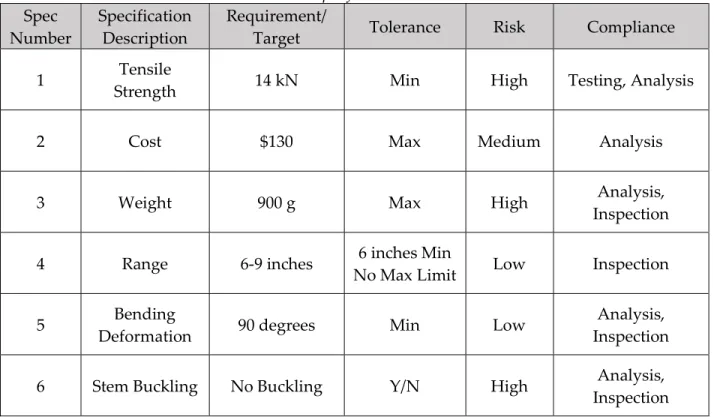
Table 5. Specifications Table Spec
Number Specification Description Requirement/ Target Tolerance Risk Compliance
1 Strength Tensile 14 kN Min High Testing, Analysis
2 Cost $130 Max Medium Analysis
3 Weight 900 g Max High Analysis,
Inspection
4 Range 6-9 inches No Max Limit 6 inches Min Low Inspection
5 Deformation Bending 90 degrees Min Low Inspection Analysis,
6 Stem Buckling No Buckling Y/N High Inspection Analysis,
3.5
Quality Function Development ProcessA Quality Function Development (QFD) table was used to help quantify the importance of the project wants and needs, and their related specifications. To start the table our team listed the customers and each of their respective needs for the device. We then benchmarked other products on the market to see how well they fit the needs of the customer. We created
1-10, 10 being very important to each group of users. Using these values, a relative weight was calculated for each of the device specifications, which helped us decide what the most important design considerations are for the design of the device. The consumer wants and needs, ranked in order of importance, are tabulated along with the corresponding engineering specifications, tolerance, risk, and method of measuring compliance. According to our QFD Chart, the most important specifications to meet are the cost, bending deformation, and stem buckling targets. While we agree that cost is an important specification, we disagree that the bending deformation and stem buckling specifications are more important than tensile strength and weight requirements. The tensile strength of the cam is critical to user safety and the
specification that dictated the shape and sizing of all the components. Also, if a cam is too heavy the user is less likely to bring it on the climb. Both weight and tensile strength are critical to the function of the device, while the flexible stem is not. The full QFD table can be found in
Appendix A: Quality Function Development Table.
4
Concept Design
Figure 4 depicts a rudimentary SolidWorks model of our chosen concept design. The trigger and the locking mechanism lack detail in in the model. However, we created this model to better understand the relative location of the individual components of the device. The following Concept Design section walks through the process we used to generate possible solutions and choose our design direction.
Figure 4. Preliminary CAD model of our chosen concept
4.1
Ideation ProcessThe ideation phase was completed in three separate sessions. Our team participated in the first ideation session, which we used to develop as many ideas as possible. During this session we brainstormed ideas for individual functions of the cam, such as expanding to fit the crack and holding the climber. During the second session we developed ideas for the following
components of a climbing cam: stem, locking mechanism, lobe shape, and trigger mechanism. We conducted the last ideation at the local climbing gym, where we invited climbers of all experience levels to brainstorm new ideas for the stem, locking mechanism, lobe shape, and trigger mechanism. This was very helpful because it allowed us to gain new ideas from people that would use our final product. For a full list of our ideas please See Appendix B: Idea Bank. We used the ideas from the ideation sessions to build functional prototypes, seen in Figure 5.
Figure 5. Two prototypes built from craft supplies. We built the prototypes based upon ideas from the ideation sessions.
The functional prototypes were made of simple materials such as cardboard, string, and hot glue. We made many prototypes with the goal of this session being to investigate the feasibility and functionality of our ideas that we had brainstormed.
4.2
Initial Conceptthe cam. The Pugh matrices compare each of the ideas against a one concept set as a datum, and they are rated on how well they solve the customer wants and needs as seen in Table 4. By analyzing the outputs of the Pugh matrices, we were able to find the solutions that best solved the wants and needs for each respective part of the cam. To combine the individual component concepts into a full cam design, we used a morphological table seen in Table 6.
Table 6. Morphological Table Showing Design A Configuration
Trigger Mechanism Stem Design Locking Mechanism
Butterfly Trigger Pure U Twist Lock
Straight Bar Pressed U Pen Lock
U-Bar Single Cable with Loop Thumb Press Lock (Tong)
Single Cable without Loop Lateral Finger Bar (Slot)
Collar
(With Butterfly Trigger)
concepts of the cam.
4.3
Concept Selection ProcessThe weighted decision matrix uses the criteria and weighting determined in our house of quality to compare each concept to our customer requirements. Each of the designs was given a rating on how well they satisfy each of the criteria. The criteria weight and the ratings were multiplied together to generate a relative success of each criteria. All these normalized successes were summed for each design to decide which design meets the criteria the best. The weighted decision matrix is shown in Table 7.
Table 7. Weighted Decision Matrix
We used four criteria to determine our best design: size, ergonomics, ease of manufacturing, and aesthetics. Size is the overall volume of the cam. Besides the cam’s lobes, we want to minimize the size and profile the cam’s triggers, stem, and carriage as to save weight and increase portability. Ergonomics is how comfortable is the cam to use. Many of the other large cams do not form to the user’s hand and require the user to stretch their hands to actuate the trigger. We do not want the user to have to strain themselves while using our cam. Ease of manufacturing is a measurement of how confident we are in our ability to construct the design. We would like to keep the design as simple as possible to reduce manufacturing cost and ease maintenance. Aesthetics is the marketability of the design. Our design needs to stand out from other cams on the market, and make users feel confident in our product.
Design A Design B Design C Design D Design E
Criteria Weighting Score Weighted
Score Score Weighted Score Score Weighted Score Score Weighted Score Score Weighted Score
Size 4 5 20 1 4 3 9 3 9 5 20
Ergonomics 3 3 9 3 9 4 12 5 15 3 9
Ease of
Manufacturing 3 3 9 5 15 4 12 2 6 1 3
Aesthetics 1 3 3 2 2 3 3 4 4 4 4
4.4
Detailed Description of Selected ConceptAfter completing our weighted decision matrix, we found that Design A best fit the criteria. As seen in Figure6, Design A consists of a four-lobe double-axle lobe design which will allow for the largest expansion range of the cam. This design also has a butterfly trigger mechanism. This trigger mechanism has two trigger bars that rotate about a fixed point on the stem.
Figure 6. Drawing of Design A, which features a butterfly trigger, a pressed U stem, and a rotating collar lock.
At the end of each of the trigger bar there is a cord that connect the lobe to the trigger
mechanism. When the climber pulls down on the trigger bars they will rotate, and the cam lobes will contract. The primary advantage of this system is that a small distance moved by the
trigger. This locking mechanism will consist of a twisting collar lock that will have slots that match with tabs on the trigger bars. When the triggers are fully contracted the tabs will slide into the slots in the collar, and the lock can be activated by spinning the collar with the user’s thumb. This will offset the slots and tabs, so the lobes stay in their fully compressed state. We built a prototype to test the feasibility of the butterfly trigger mechanism, and this can be seen in Figure 7.
Figure 7. Concept Prototype for butterfly trigger mechanism
This prototype proved that the butterfly trigger is feasible, and the following offered valuable lessons moving forward. First, we learned that the placement of the trigger along the stem will have a large effect on the comfort of the device. Similarly, the attachment points on the lobes will influence the contraction of the lobes. More prototyping will be needed to find the best positions for attaching the butterfly trigger mechanism to the cam.
4.5
Preliminary Analysisusing finite element analysis (FEA) beginning in January. To ensure that we obtain accurate FEA analysis, we needed to start with proper loading cases. Using Figure 8, we found that when a 14 kN force was applied (T) at a 13-degree camming angle (α), the reactionary force was 15.6 kN. Similarly, for a 14 kN force applied at a 16-degree angle, the reactionary force was 12.7 kN. This provides us with the cam lobe loading as well as the shear force that will be applied to the axles.
Figure 8. Calculation used to find the reaction forces acting on the cam lobes [27]
We also needed to find the minimum wire cable stem thickness. Using Figure 9, we found that a 3/16” diameter cable would be sufficient for a 14 kN (3147 pounds) loading.
Figure 9. Strength of wire rope based on diameter [28]
4.6
Risks, Challenges, & Unknownsthis project. We also anticipated the need to design a custom fixture or jig for tensile testing. In terms of risks that would affect the user, we acknowledge the risk that is posed to the climber when they are using this device. While our primary goal is to keep the climber safe while they are placing the gear, the climber does accept a risk when they decide to take on a trad route. Aside from the obvious safety hazard here, other possible risks to the user are that it is possible that they could pinch their fingers between the rotating cam lobes, that the spring being too stiff could prevent the user from being able to actuate the trigger during a climbing route if their arms are fatigued, and that if the device is improperly placed the cam can fail to hold them under the impact of their fall. All these safety risks mentioned will be made very clear to the user of this device using the instruction manual that we intend to produce by the exposition. These safety risks are tabulated in Appendix D: Design Hazard Checklist, after the completion of a hazard checklist is documented.
5
Final Design
(a) (b)
Figure 10 (a). Final Design Assembly Note: Trigger Cords not Pictured
Figure 10 (b): Manufactured Final Cam
The cam consists of three subassemblies (the head, stem, and trigger subassemblies) connected at one main junction (the carriage). The head subassembly consists of the lobes, axles, springs, axle linkages, and fasteners. The stem subassembly consists of the stem, stem cap, and sleeves. The trigger subassembly consists of the triggers, fasteners, and trigger cord. Figure 11
illustrates the position of the head and the triggers during different stages of activation.
H
ea
d
Tri
gg
er
Figure 11. From Left to right: unactuated, partially actuated, fully actuated
The lobes are machined from 6061-T6 Aluminum and pivot around the axles which are turned down to size from 17-4 PH stainless steel stock. Torsional steel springs maintain the expanded position of the lobes when the device is not actuated and sits on the axle along with snap rings to maintain the axial position of the lobes. The carriage houses the axles as well as the wire cable stem. A future goal of ours is to is to cut out as much weight as possible from the carriage while meeting the structural requirements for the cam. Moving forward, the exact geometry of the carriage would be guided using analysis from FEA. The stem, which is made of 3/16” 1x19 Stainless Steel Aircraft Cable, is crimped on both sides of the carriage using swages. The triggers activate the lobes via 2.75 mm accessory cord that are glued into the lobes.
5.1
Lobe Design and AnalysisFigure 12. Final Lobe Design
Figure 13: Lobe Abaqus Model
We started our finite element analysis by performing a convergence study to determine the best mesh size and mesh type. We determined that linear hexahedral elements with a global mesh size of 2-mm worked best, as it is a good balance between computation time and accuracy. We also found that at the current lobe thickness, the lobe’s maximum principle stress is less than 6061’s yield strength, giving us confidence that it will not yield under load. The lobe’s von-mises stress distribution can be seen in Figure 14, and the convergence study can be found in Appendix F: Lobe FEA Convergence Study .
Figure 14: Von Mises Plot (Global Mesh Size: 1.5 mm, Linear Hexahedral Elements) 13.52 kN load distributed across contact patch BC: Completely Fixed
Contact with fixed “axle”
Once we determined what mesh we wanted to use, we then performed a linear buckling analysis. Interestingly, Abaqus would not allow us to use a contact with a linear buckling step. To get around this limitation, we paired the contact interaction to an initial static analysis step, then added a subsequent buckling step with a load of 1 N/mm2. Normally, the eigenvalues from the linear buckling analysis describe the load scaler causing the part to buckle. With our two-step approach, however, this made the eigenvalues represent the added load needed to buckle the lobe. We found that the lobe would reach its first mode of buckling with an added load of about 298 N/mm2 or another 52.77 kN, as seen in Figure 15. In other words, the lobe would yield before it would buckle.
We then tested the model at five different thicknesses: our original thickness 13.21 mm, 11.5 mm, 10 mm, 8 mm, and the thinnest lobe currently on the market 6 mm. We performed the same two-step buckling process as before, making sure to change the surface traction load since the contact patch area changes. Figure 16 graphically summarizes our results for the minimum lobe thickness.
Figure 15: First Linear Buckling Mode
As expected, as we thinned the lobe, the principal stress increased, and the buckling eigenvalue decreased. None of tested thickness are likely to buckle, still having positive eigenvalues. But for thicknesses 10 mm and less, the simulation predicts the lobes would begin to yield under the 13.52 kN load. Thus, our minimum lobe thickness is approximately 10.6 mm or 0.4 in. We were skeptical of this result, as most other large cams’ lobes are about 0.3 in thick. So, for our
verification prototype, we manufactured lobes that are 0.3 in thick, in line with other cams on the market. We intended determine if the new thickness would fail under load using a tensile test, however, due to COVID-19, we did not have access to the campus testing facilities, and thus were unable to determine if the thinner lobe thickness is viable.
5.2
Carriage Design and AnalysisThe carriage is the interaction point between the stem and the lobes, making it the main hub of the camming device. The carriage, shown in Figure 17, is made from 6061 T6 Aluminum, and is based upon similar cams that are on the market
0 50 100 150 200 250 300 350 0 50 100 150 200 250 300 350
4 5 6 7 8 9 10 11 12 13 14
Pr in ci pa l S tr es s on In ne r F ac e of L og S pi ra l ( M Pa ) Ei ge nv al ue o r A dd ed L oa d to B uc kl e (N /m m 2)
Lobe Thickness (mm)
Buckling Optimization Stress Stress Limit Eigen Value Limit
Figure 16: Lobe Thickness Optimization Plot
Thinner is better
Figure 17. Carriage with Axles
The carriage was optimized using finite element analysis. The FEA model used symmetry boundary conditions because the loading about the carriage is symmetrical. Because of this only half of the carriage was analyzed in Abaqus. This allowed us to save time while running the analysis of the carriage and simplified the boundary conditions into fixed boundary condition where the carriage is cut in half. The FEA analysis can be seen in Figure 18 and Figure 19.
17-4 PH stainless steel. We were never able to figure out why this was the case, but we think it may have to do with the lobes taking more of the loads as the axles get pushed apart. However, the main use of this FEA model was to look at the stresses in the carriage. The stresses in the middle of the carriage are very low, and the material is not needed. We tried to optimize the carriage and remove material in the carriage and the following model was found.
Figure 19: FEA of Carriage with Reduced Center
This model showed that the material in the center of the carriage is not needed because it sees such a low stress. Although the stresses in our model are very high, they show the correct stress distribution of the stresses in the carriage and axle. This stress distribution validates our
decision to remove material in the center of the carriage, but more testing is needed to completely verify the design.
5.3
Axle Design and AnalysisFigure 20. Axle Linkage and Snap Rings
This allows the horizontal forces from opposing lobes to cancel out so the only force on the axle was the vertical force. This led to an axle sizing that was comparable to other cams at 0.325 inches. Although the axle we choose is smaller the calculations indicate, the analysis is still a conservative approach, and our chosen axle is comparable to other camming devices.
Figure 21: Von Mises Stress FEA of Carriage, Axles, and Axle Link
To further model the system, we ran an FEA analysis on the axles and the end caps to minimize the size of the axle to reduce weight. Through this analysis we found that the max stress in the axles was 265 ksi which is greater than the yield strength of the axles. Although this is the case, we believe that there are other interactions that are happening between the lobes and the axles
Axle
Axle Linkage
Snap Ring
and our planned tests can be seen the design verification section. A complete calculation for the axle system can be found in Appendix E: Hand Calculations.
5.4
Stem Design and AnalysisThe stem will consist of a wire cable with a sleeve, looped back once to form the thumb loop at the bottom of the cam. We selected 3/16” type 302/304 stainless steel aircraft cable. For the structural prototype we ordered 7x19 cord and 1x19 cord because they have different flexibilities, but both meet our strength requirement for the stem. After the prototype was completed, we found that the 7x19 cable did not provide enough stiffness. Because of this our final design is 1x19 cable wrapped in tape to eliminate any pinch points in the stem. To connect the stem to the carriage we will use three swages as seen in Figure 22.
Figure 22. Three swage carriage connection
We plan to use three swages to test the effectiveness of the swages for connecting the stem to the carriage. If the swages slip while tensile testing, we will need to implement a different mechanism to connect the carriage and the stem.
5.5
Trigger Design and Analysiscontract the lobes when actuated. To alleviate this problem, we have altered our design to implement a double hinged mechanism, shown in Figure 23,
Figure 23. Trigger Assembly
This double hinge will allow the cam to fully contract while still maintaining ease of use. The double hinge will allow for extra activation of the lobe without increasing the size of the triggers. The triggers are connected to the stem with a tiller clamp. This allows us easy
interchangeability and the ability to test different positions for the triggers as seen in Figure 24. The triggers are connected to the lobes with a 2.75 mm Accessory Cord. We chose 2.75 mm Accessory Cord because of its flexibility and durability.
Figure 24. Exploded Trigger Assembly
5.6
Cost Analysis by ComponentPrior the COVID-19 pandemic, our goal was to build 10 prototypes: 5 for iteration, 1 for each of us, and 1 for our sponsor. Since we anticipated constructing multiple prototypes, to save, we bought the aluminum for the lobes and carriages in bulk, which greatly reduced the cost per cam. We consulted Professor Trian Georgeou of Cal Poly’s Industrial Manufacturing
Engineering Department to find out where Cal Poly purchases their metal stock, and he
informed us that Coast Aluminum was the best supplier to meet our needs. Coast Aluminum is located out of Fresno, California and can deliver the material directly to Cal Poly within two days of our order.
The most expensive item for this project is the bar stock aluminum for the cams’ lobes. Each lobe is approximately 8 inches in length, so we need 2.75 feet of bar stock the four lobes on each cam. Coast Aluminum sells aluminum stock in 12-foot lengths. Thus, for our planned 10 cams, we needed 3 lengths of aluminum, which is $325.08 in total.
The other item we ordered from Coast Aluminum are the aluminum bar stock for the cams’ carriages. Each carriage is approximately 3.5 inches in length; thus, we need about 3 feet for the ten cams, leaving 9 feet of extra stock. However, the 12 feet of aluminum bar stock will cost $175.67, which is a great price, as to purchase just 3 feet from other suppliers like
OnlineMetals.com would cost over $100.
Since our other fabricated components are smaller in size, we do not need to purchase material in bulk. For our stem cables, purchasing the steel cable from Lexco Cables, which was
recommended to us by Myles Wittman. The stem cables will cost us about $43.38 total for the 15 feet of cable necessary for ten cams. Both The 17-4PH stainless steel and the for the cams’ axles and the 6061-aluminum round stock for the cable-caps were purchased through
OnlineMetals.com, costing $104.76 and $11.56, respectively. The 14-gauge, 304 stainless steel sheet metal for the axle linkages came from MetalsDepot.com with a total price of $39.95. The 0.047 in diameter music wire we used for the axle springs were purchased from Amazon for $50.80. Finally, through Innovation Sandbox, our triggers were completely free, allowing us to make a couple iterations for no cost.
Table 8. Reduced Cost Table
Subassembly Part Number Component Supplier Total Cost
Carriage 100 Carriage Coast Aluminum $175.67
Head Assembly
210 Axles Online Metals $74.05
220 Lobes Coast Aluminum $325.51
230 Axle Linkages Metals Depot $43.07
240 Axle Springs Amazon $8.14
250 Snap Rings McMaster-Carr $16.72
Stem Assembly
310 Stem Cable Lexco Cable $41.38
320 Swage McMaster-Carr $52.55
330 Electrical Tape Home Depot $4.75
Trigger Assembly
410 Trigger A Innovation Sandbox $0.00
420 Trigger B Innovation Sandbox $0.00
430 Trigger Cord Amazon $24.67
440 + 450 Tiller Wire Clamp
+ Flathead Screw Amazon $34.96
460+470 Through Screw + Nut Home Depot $2.36
Total: $804.13
To help pay for the material costs, we submitted a proposal to the Mechanical Engineering Student Fee Allocation Committee (MESFAC) to gain funding for our iteration prototypes. Fortunately, on February 7th, MESFAC granted us $835.40, providing us the funds we need for the metal stock and other materials.
Unfortunately, due to COVID-19, we were unable to complete the manufacturing for the first cam that we began during winter quarter. The remaining machining included the carriage, axles, and axle links. Since we did not have access to campus spring quarter, we decided to outsource the last of the machining to Rogue Engineering. The last of the machining cost $349.75. Fortunately, we received $200 from CP Connect to help pay for the last of
5.7
Safety AnalysisSafety is a major priority when designing a camming device because the camming device is used as a protection device. With the inherent risk of rock climbing, any structural failure can result in a possibility of a life-threatening injury. We have conducted a Failure Modes and Effects Analysis (FMEA), for our camming device, and it can be seen in Appendix H: Failure Modes and Effects Analysis. Through this analysis, we found that a lot of failures have a high risk including the following: lobe breaking, lobe buckling, axle breaking, carriage breaking, and stem breaking. Any of these failures would result in the climber falling and potentially a life-threatening injury. To address these concerns, we followed industry leaders in rating our camming device to a 14 kN load, to decrease the occurrence of these failure modes. In addition to failure analysis, we will be conducting tests to ensure that the device can hold the required load. The only way to detect the possibilities of these failures is by inspection, which is done when the device is manufactured. In addition, the user of the device should inspect the device completely for any visual flaws prior to each use to reduce the risk of unexpected failure.
However, the device cannot be completely safe because failure of the rock that the cam is placed in can occur.
Proper care of the device is important to ensure it works properly. The cam should be cleaned when dirty to prevent the seizing of the camming device, as well as uncover any flaws that were hidden by dirt or grime. The device should be properly stored in a cool dry space away from direct sunlight. If the trigger cords become frayed or break, they can be repaired, with a replacement kit of trigger cords. If any other part of the cam has a flaw, repair is not an option for that cam. In Appendix I: Operations Manual, we have outlined the correct handling of the device to maximize the lifespan of the cam.
6
Manufacturing
The following manufacturing plan provides a step by step process of how our final design was created and assembled. All materials outlined in this section are detailed in the indented bill of materials seen in Appendix J: Indented Bill of Material. This section is broken into subsections based on the component. A final assembly subsection is included last.
6.1
Carriage Soft Jawsholding geometry into the soft jaws. Finally, a hand file was used to remove any burrs left on the soft jaws.
6.2
CarriageThe carriage was machined by Noel Rodes at Rogue Engineering. The shape of the carriage resembles a three-dimensional H, shown in Figure 25, with two holes running the length of the two vertical lines and two holes side by side in the middle of the bridge perpendicular to the previous holes.
Figure 25. The carriage component for the final cam design.
The vertical holes house the axles while the perpendicular holes are used to attach the stem. (Picture) A CNC mill loaded with a 9/32-inch drill, a 5/16-inch reamer, a 1/2-inch chamfer tool, a 3/16-inch drill, and a 1/2-inch flat end mill was used along with the proper CNC programs. The carriage was secured to the mill table with a vise and the carriage soft jaws. It was then
cut in four operations. The first operation contoured the external H-shape of the carriage and chamfers the top edges. The two stem holes were also drilled. The part was flipped, and the second operation faced the part to the appropriate thickness. The bottom was chamfered. The part was turned on its side and the axle holes were drilled halfway. The edges and holes were chamfered. The part was flipped again, and the final operation finished the axle holes. The reamer was used to ensure the holes were within specification. The remaining edges and holes were chamfered. A deburring tool was used to break all sharp edges.
6.3
Stemsling, the final stem subsystem is shown in Figure 26.
Figure 26. The stem made of the stainless steel aircraft cable, and the sling attached to the thumb loop.
6.4
AxlesA manual lathe loaded with a stop, a tail stock, a CNMG-432 insert tool, a 1/2-inch center drill, a live center, and a grooving tool, were needed for this process. The part was loaded into the jaws until there was about an inch of stick out and the machine jaws were tightened. The part
underwent four operations. The first faced one end and drilled a center hole using the tail stock. The part was flipped, and the operation was repeated. The part was reloaded using the stop, tail stock, and live center. Half the length was turned to the proper diameter in three passes. Finally, a 1/32-inch grooving tool available in the shop was used to cut the groove. The part was flipped, and the operation was repeated. A final axle is shown in
Figure 27. One of the two finished axles.
6.5
Lobe Soft JawsCustom soft jaws were required to hold the unique shape of the lobes into the vise while they were being machined. To make the soft jaws for the lobes, a CNC mill loaded with a 1/2-inch end mill and the proper CNC program was used. The soft jaws were first loaded into a vise on the table of the CNC mill. They were then adjusted, using a test indicator for guidance, so that they were parallel to the machine table. The CNC program was run, cutting the holding geometry into the soft jaws. Finally, a file was used to remove any burrs left on the soft jaws.
6.6
LobesA CNC mill loaded with a 1/2-inch chamfer tool, a 3-inch facing tool, a 1/8-inch drill, a 3/16-inch drill, a 1/4-inch flat end mill, and a 1-inch flat end mill were needed along with the proper CNC program and a set of parallels. Each lobe was cut in two operations. For the first operation, the lobe was loaded into the vise with a pair of 1 7/8-in. parallels. The part was contoured and then the holes and pockets were cut. The part was flipped and loaded into the vise with the soft jaws. The second operation faced the rest of the stock from the opposite side of the part and
Figure 28. One of the finished lobes. We obtained this shape through extensive FEA.
6.7
SpringsEach spring was wound by hand due to their unique shape. Two springs are needed for each cam. A pair of needle nose pliers, a pair of lineman pliers, and a 3/8” round bar was needed to make the springs. Using a tape measure and marker, a mark was placed at .5, 1.0, 4.0, 7.0, 10.0, 10.5, and 11.0 inches. The wire was cut at 11 inches using the lineman pliers. A 90-degree bend was place at .5 and 10.5 inches using both pairs of pliers. These bends must be 180-degree from each other. Using the lineman pliers to grab onto the .5-inch bend, and with the round rod held in place between the pocket of the lineman pliers, the wire was wrapped around the rod in a tight clockwise pattern. The 1- and 4-inch mark should be lined up after two full rotations. This process was repeated on the other end of the wire. The second wire is made in the same
Figure 29. The finished torsional springs.
6.8
Axle LinkageThe axle linkages, one of which is shown in Figure 30, were machined by Rogue Engineering. A 1-inch strip of material was cut. The material was clamped to a piece of plywood on one side and a strip of aluminum on the other. The holes were drilled, and nuts and bolts were used to hold the three pieces together. The part was then loaded into a CNC machine and the profile was machined. All sharp edges were broken with a file.
6.9
TriggersAn STL file was created using SolidWorks and submitted to the Innovation Sandbox, a free service offered to Cal Poly students on campus, to be 3D printed. This process took between three days and one week. Sandpaper was used to round any sharp edges or flatten any rough surfaces. Some holes were re-drilled using a drill press. A finished trigger is shown in Figure 31.
Figure 31. Finished trigger handle.
6.10
Trigger CordThe 2.7mm accessory cord was cut during the assembly process and will be described in Section 6.13. A double fisherman’s knot and glue were used to secure the string to the lobes.
6.11
Nylon SlingA nylon sling is used to connect the climber’s rope to the cam. 1-inch tubular webbing was sewn into a loop by Myles Wittman.
6.12
Assembly:Figure 32. Sling attached to the thumb loop.
to the stem.
A gap was left between the two swages to analyze any movement during testing. Excess wire was cut using bolt cutters. The axles were then put into the carriage and the first lobe was placed onto the axles. The first spring was placed over the axles and then attached to the first lobe. The second lobe was placed onto the axles and attached to the other end of the spring. The operation was repeated on the other side. The axle links were slid onto the axles and a snap ring is placed onto the end of each axle. The lobes secured in this way are shown in Figure 34.
Figure 34. Lobes secured to the axles and carriage subassembly using snap rings.
Figure 35. Fully assembled camming device.
All individual component drawings as well as the assembly can be found in Appendix K: Drawing Package.
6.13
Challenges and RecommendationsIt was difficult to find manufacturers and the cost of prototyping can be very expensive. When you outsource that cost is greatly increased. Therefore, it is recommended that as much
machining be done in house as possible.
Swaging around the carriage can also be difficult. In order to prevent any potential failures, the last two swages should be crimped before the one at the bottom of the carriage. This ensures that the load bearing swages are properly set.
7
Design Verification
Prior to the COVID-19 outbreak and campus closure, we were planning to test our camming device design to determine it met the specifications listed in Table 5: tensile strength, cost, weight, range, bending deformation, and stem buckling. A complete summary of our former design verification plan can be found in Appendix L: Design Verification Plan. However, since Cal Poly campus is closed and we do not have access to a machine shop or tensile tester, we were unable to complete all the tests to determine whether our camming meets theses
procedures can be found in Appendix M: Test Procedures.
7.1
Completed Tests and ResultsSince we were able to construct a single verification prototype, we were able to complete all the non-destructive specification tests. Firstly, we have the maximum cost-to-manufacture
The next specification test was to determine the camming range. We designed the cam to have a usable range of 6 to 9 inches. To test the range, we placed the cam in the same test fixture as the planned tensile tests. A description and picture of the test fixture can be found in the Section 5.7 Incomplete Tests. By adjusting the distance between the test fixture’s steel plates, we placed the cam at its maximum and minimum activation, and measured the distance between the contact points using a ruler, as depicted in Figure 37. We measured the cam’s range to be between 6 to 9 inches wide, fulfilling our design specification.
(a) (b)
Figure 37. Using a ruler to measure the distance between the lobes’ contact points when it is (a) unactuated and (b) 100% actuated.
(a) (b)
Figure 38. Using a weight to simulate a bend test of the stem. (a) The cam in the test jig without a weight attached. (b) The cam’s stem was able to bend around a 90 degree corner without sustaining permanent deformation.
Figure 39. Testing that the stem does not buckle during the actuation of the cam.
7.2
Incomplete TestsUnfortunately, the one test we were unable to complete was also the most integral for
Figure 40. Black Diamond Pull-testing a Cam in Umbrella Mode [28]
(a) (b) (c)
Figure 41. Tensile testing equipment. (a) Tensile Test Fixture, (b) Sample Cam within Test Fixture, (c) Ametek Tensile Tester Jaws
Our plan was to first test one camming device from an external manufacturer to verify that our test fixture works, and the cam does not slip. Also, since the cam has a specified rated failure load from the manufacturer, we can verify that the tensile tester and our test procedure yields accurate data. In addition, we were going to tensile test different configurations of webbing that attaches to the cam. Following these initial calibration tests, we would then begin testing our own cams. If the cam successfully supported the 14 kN load without any component yielding, then we would go back to the drawing board and use further FEA and testing to eliminate unnecessary material from the design. In doing this we would be working towards make the cam as light as possible while still maintaining the required 14 kN tensile strength. If our cam failed under load, we would use both the tensile test data as well as visual inspection to diagnose where the design failed and be able to identify how to alleviate the problem, summarized in our Failure Mode Analysis found in Appendix H. We would then repeat this process until our final design meets all our design specifications. The detailed tensile test procedure can be found in Appendix M: Testing Procedures.
8
Project Management
The Project Management section outlines the plan that we made to complete our project and meet the key deliverables we aimed to fulfill. It explains the design process taken from
conceptualization to the final design, and how we evaluated the effectiveness of the final cam. To see a full breakdown of tasks and please refer to Appendix N: Gantt Chart.
8.1
Overall Design Processcomponent before the outbreak of COVID-19, however at the time we dismissed this as an unimportant decision. Looking backwards, coming to a design decision on all components before beginning manufacturing would have answered a lot of the questions that we have now. If we could change one thing, it would be to have had all final design decisions made before manufacturing. Mixing the design development of the triggers with the manufacturing steps would not have been detrimental had it not been for the COVID outbreak. In fact, because of this, we would have changed several things in our process. We also would have applied for additional funding to cover the costs of outsourcing some of the manufacturing processes, however this was much more out of our control. On a similar note, we cannot stress enough the importance of planning ahead. A well-thought out Gantt chart and making our plan as detailed as possible would have been time-saving in the wake of the global health emergency.
The assignment of specific roles on the team proved to be an effective way of each of us knowing generally what we are responsible for was useful. The Team Gantt software enabled this practice, and it was useful that we were reminded of upcoming deadlines that we were individually responsible for.
8.2
Unique Processes UsedThese are the following unique processes that we used for design, prototyping, and building.
Finite Element Methods for Design:
We used the software Abaqus to conduct Finite Element Analysis on the carriage and lobe components. The purpose of this was to shave as much weight off the cam as possible, without compromising strength and durability.
Tensile Testing the Structural Cams:
As a part of the testing procedures, we planned to utilize the Ametek pull-tester with a custom jig to pull the cams until breaking. Unfortunately, due to the campus closure, we did not end up using this method.
Trigger Design:
9
Conclusion
The goals of this project were to design, build, and test a strong and lightweight camming device for off-width climbing that features a flexible stem. Additionally, we wanted to improve upon the ergonomics of the limited options for a large camming device currently on the market. These goals were mostly achieved during throughout the entire design process. During the first two quarters of the project, our team designed and built a novel camming device.
One large goal of ours was to build test and iterate on our design to improve the device. However, we were unable to test the device to verify that it met all our specifications. The largest hurdle that faced this project was the closure of the Cal Poly Campus due to the COVID-19 outbreak. Due to this closure, our plans to manufacture and test the cams ourselves on the Cal Poly Campus were no longer possible. Instead we quickly adapted and located external manufactures to continue to build the device for us. However, due to the unpredictable nature of the pandemic, we lacked sufficient funding to outsource the production of ten camming devices that we could test. Instead we got a single cam build be a manufacture as an initial prototype.
9.1
Next Steps:Although we are building and testing the design direction stated in this report, we would like to iterate the final design several times based on the results of this and all subsequent testing. We also recommend iterating the lobe design and the geometry of the carriage based on further FEA to reduce the weight of the overall device. The trigger sizing would continue to be modified once we have more structural prototypes to bring to the local climbing gym and obtain feedback from climbers. Moving forward, we would test multiple families of devices. The first test that will be conducted would determine the best manufacturing method for the stem to carriage connection. After this test, we would test the optimized carriage dimensions. The final few prototypes would be built for aesthetics. For these more finalized devices, we would use plastic injection molding to produce a sleeve for the wire cable that will contribute to the stiffness of the cable. This would also be the final ergonomic decision to implement, and for this we would require more user feedback.
One aspect of the device that still needs to be designed is the sleeve that encapsulate the wires in the stem. This sleeve increases the stiffness of the cam allowing the cam to be stable while in use. If more time were available, we would injection mold a plastic sleeve with different
thicknesses in different areas that need stiffness. This variable stiffness would need to be tested to ensure that the stem of the cam does not buckle during use, and it is not too stiff as to prevent flexibility in the stem.
available. Although the swage supports the necessary loads, we would look to find a more elegant solution to increase the aesthetics of the device and reduce the weight. In addition, the new solution would need to simplify the assembly of the device.
Another modification to the cam that would be added if there was more time would be to anodize the lobes. This would increase the durability and the corrosion resistance of the lobes. Finally, a one-handed locking mechanism would be a necessary feature for this cam in the future. Although this was a goal of ours, with time constraints we were not able to implement a locking mechanism for the cam.
9.2
ReflectionOver the duration of this project, the tasks we completed well were the following: locating sufficient funding to cover our initial projections, reaching out to industry experts for help and resources, locating a testing location, brainstorming ideas, and lastly our time-management improved sufficiently when we started having more regular “check-in” meetings.
Similarly, there are many things that we could have done better throughout the project. First, we could have made design decisions earlier on. This problem was accompanied by too much time planning, and not enough testing new ideas quickly with simple prototypes. This would have allowed us to find new solutions to our problems more quickly and allowed us to progress with new designs. With respect to analysis we could have completed the FEA on the axle and carriage more promptly. The largest issue with this was that we were not experts using FEA and were learning the finite element method while trying to complete analysis for our device. Because of this completing the analysis took much longer than anticipated because we ran into problems that we did not know how to fix quickly. This set back the final design of the cam and restricted the amount of testing that we were able to complete. Overall allocating our time and resources properly was our biggest internal issue that we faced during the project. This was a direct effect of this being our first major long-term project, and we were learning and refining our design process throughout.
Ultimately, during this project we learned how invaluable it is to build early prototypes, as having a physical object to manipulate and test significantly cuts the amount of time

![Figure 8. Calculation used to find the reaction forces acting on the cam lobes [27]](https://thumb-us.123doks.com/thumbv2/123dok_us/8220947.2179567/25.918.216.705.287.590/figure-calculation-used-reaction-forces-acting-cam-lobes.webp)