Left Atrial Model
Final Report Draft
Tess Pate
Borna Sobati
Sarah Porrello
[email protected]
[email protected]
[email protected]
Sponsor: Dr. Chris Porterfield
Table of Contents
1.0 Executive Summary
2.0 Introduction and Background
3.0 Customer Requirements and Design Specifications 3.1 IFU
3.2 Product Design Specifications 3.3 House of Quality
4.0 Stage Gate Process 4.1 Concept Review 4.2 Design Freeze 4.3 Design Review
5.0 Description of Final Prototype Design 5.1 Overview
5.2 Design Justification 5.3 Analysis
5.4 Cost Breakdown 5.5 Safety Considerations 6.0 Prototype Development
6.1 Model Analyses
6.2 Evolution of Prototypes 6.3 Manufacturing Process
6.4 Divergence Between Final Design and Final Functional Prototype 7.0 IQ/OQ/PQ
7.1 DOE
7.2 Verification and Validation 8.0 Conclusions and Recommendations
8.1 Recommendations 8.2 Conclusions 9.0 Acknowledgments 10.0 Appendices
10.1 Appendix A: References
10.2 Appendix B: Project Plan (PERT Chart) 10.3 Appendix C: CAD Drawings
10.4 Appendix D: FMEA, Hazard & Risk Assessment 10.5 Appendix E: Pugh Chart
10.6 Appendix F: Vendor Information, Specifications, and Data Sheets 10.7 Appendix G: Budget
1.0 Executive Summary
This document provides information on the purpose of the Left Atrial Model project and its specifications. Objectives and expectations are outlined, and an overview of the project management will provide guidelines for time.
2.0 Introduction and Background
The objective is to produce an electrophysiological model of an adult human left atrium. This model will be used to test mapping probe catheters used for locating cardiac arrhythmias against current technology used in practice. Dr. Chris Porterfield requested this model and other physicians or probe catheter manufacturers may also use this product in the future. Dr. Porterfield also discussed the possibility of future senior project groups using the model as a bench test for designing new catheter tips. The model will precisely simulate electrical behaviors of the heart in normal as well as arrhythmic conditions. Ideally, the model will be used to place an arrhythmia at a known location, and the mapping catheters will sense where the arrhythmia is located. The results from sensing the model will be compared to the results shown on the 3D mapping system to evaluate the precision of the catheter used in conjunction with the 3D mapping system.
Summaries of Customer Meetings
Week 1: 1/16/19 Dr. Porterfield specified that the shape of the atrial model should be generally related to actual heart anatomy, but that a simplified shape could be used to still meet his expectations. He also said that he has tried to obtain a model that is currently used by Abbott for the same purposes, but has not been successful because they are weary of sharing
intellectual property. On the topic of related models, he said that most current models are used submerged in a saline bath but that a dry model would also be acceptable. It was also agreed upon that the model could be scaled larger than an actual heart as long as the electrode density would lend to be able to test for accuracy with a 9mm2 accuracy. A team at University of Michigan has been working on creating a similar model using a conductive material instead of ballistics gel and was not successful with that material.
Week 2: 1/23/19 We showed Dr. Porterfield a rough 3D print of a heart to see if he was
satisfied with the shape. We also showed him the gel so he could feel the material and provide any input. He said the gel was appropriate for the project.
Week 3: 1/30/19 We met Dr. Porterfield at the hospital to observe an ablation procedure. We were familiarized with the procedure itself, the mapping catheters, and the mapping system. Two members of the team also did dissection on a porcine heart to become familiar with cardiac anatomy.
designs in the future. In regards to testing accuracy, we asked if someone could test our model against the mapping system used in the hospital. He said the model could be tested by him or one of his associates.
Week 5: 2/13/19 We talked about the scale of the model and presented our current design concepts. Dr. Porterfield expressed that a 2:1 scale model would be best for testing.
Discussion of Existing Designs
There are physical as well as CAD models of the human heart that are used for simulations, surgery practice, and academic use. Electrodes also exist for the purpose of mapping electrical activity on the surface of the brain and heart, but there is no documented in vitro model that combined the two to be electrophysiologically accurate. Most models used for this purpose are ex vivo models consisting of bovine or swine myocardium in a circulating bath [10]. A recent business intelligence study by Transparency Market Research has estimated that the global ET catheter ablation market will be worth US $2.74 billion by the end of 2026 [12]. Because of this competitive nature to be cutting edge in the electrophysiology field, there is not much
information available about similar models that are being produced. Dr. Porterfield mentioned that a group working on a similar project was not successful using a conductive material to cast the shape of the heart, so it is more productive to begin prototyping using ballistics gel. Dr. Porterfield also mentioned that current in vitro heart models are commonly dunked in a saline bath before used for testing. Abbott has been contacted about the possibility of them sharing information about their model, but it is proprietary and cannot be shared.It’s known that some companies use porcine hearts in saline solution to simulate similar conditions.
While there is not much information available about similar models, there are plenty of different mapping catheters that could be used in the model to evaluate their accuracy.
Table 1: Mapping Catheters that can be used in Left Atrial Model
Catheter Name Company Description
Advisor HD Grid [1] Abbott Bi-directional high-density
mapping catheter; 12 electrodes
Achieve Advance [9] Medtronic Circular loop with 8 evenly spaced electrodes for mapping electrical
conduction between the left atrium and pulmonary veins
Intellamap Orion [5] Boston Scientific Bi-directional 180 degree curve “balloon”; 64 electrodes
electrodes that can be used for simulation and recording; 10 or 20 electrodes
Related Patents
Table 2: Relevant Patents to the Left Atrial Model
US Patent No. (s) Patent Name Applicant
10,136,829 Systems and methods for
using electrophysiology properties for classifying arrhythmia sources
St. Jude Medical, Cardiology Division, Inc. 6,233,476; 6,556,695; 7,365,745; 7,774,051; 7,825,925; 7,855,707; 7,894,871; 7,988,639; 8,038,625; 8,130,221; 8,229,545; 8,253,725; 8,352,019; 8,364,253; 8,454,538; 8,454,589; 8,647,284; 8,825,144; 8,805,490; 8,849,393; 9,026,196; 9,078,591; 9,111,175; 9,113,807; 9,137,611; 9,159,162; 9,198,601; 9,204,927; 9,237,920; 9,392,973; 9,339,325; 9,486,152; 9,549,689; 9,560,988; 9,585,586; 9,591,990; 9,597,036; 9,610,027; 9,956,049 Multiple names
(All patents for EnSite Precision Cardiac Mapping System owned by Abbott)
Multiple
Owned by Abbott
9,950,141 Dual braid reinforcement
deflectable device (sheath or catheter)
St. Jude Medical, Atrial Fibrillation Division, Inc.
10,143,374 Systems, devices,
components and methods for detecting the locations of sources of cardiac rhythm disorders in a patient's heart
Ablacon Inc.
10,149,626 Methods and systems for
mapping and ablation of cardiac arrhythmias comprising atrial flutter
Relevant Technical Literature
As of 2001, it was estimated that approximately 2.3 million US adults have atrial fibrillation (AFib), and that number is expected to increase to more than 5.6 million by the year 2050 [8]. In itself, AFib is not dangerous, but the complications that arise from it can be lethal. The atria of the heart have appendages that provide a perfect nook for clots to form when the heart is in AFib, which can then travel from the heart and lead to stroke [2]. Currently, the most common technique for treating atrial fibrillation is catheter ablation, but studies have shown that 1 in 8 patients may require a repeat ablation within 1 year, and up to 40% of patients will require a repeat ablation within 5 years [3,8]. As any medical procedure, ablations may place a large financial burden on patients ranging from $16,278 to $21,294, so it is desirable to complete the first procedure as thoroughly as possible [7]. An ablation procedure is performed by first
threading catheters from the jugular and femoral veins to the heart, and then continues with 3D mapping of the heart using specialized mapping catheters [3]. These catheters come in
different shapes with different electrode orientations that the physician will use at their
discretion. The accuracy of these mapping catheters is integral to the success of the procedure because it determines the resolution of the 3D map that is produced. Currently, physicians do not have an easily accessible way to test the accuracy of the catheters that they can choose between before using it in a surgical setting. The companies that are selling these products will market improved accuracy, but the physicians are not provided with a method to test these claims outside of a patient. It is very important for a physician to be confident in a new tool before using it in surgery.
Applicable Industry Regulations
Since this is an in vitro model and is not designed to come into contact with biological systems, it is not considered a medical device. This greatly reduces the amount of codes and standards that the model itself must meet. However, the Class 2 or Class 3 ablation catheters that will be used are already FDA compliant.
3.0 Customer Requirements and Design Specifications
3.1 IFU
The Left Atrial Model is an electrophysiological model of the left atrium of the heart intended for use by clinicians or future senior project groups that are designing catheters. The device provides a way to simulate arrhythmias on a flat bench test in order to test probe catheters that are used in cardiac ablations. The modeled arrhythmia location is intended to be compared with results from the probe used in a current mapping system in order to determine probe accuracy. This will allow physicians to make an informed decision on which catheters to use in their procedures, or will allow senior project groups to verify their prototype designs.
3.2 Product Design Specifications
voltage output. The repeatability is reliant on the lifespan of the product, electrode density, and electrode half-cell potential.
Customer Requirement
Engineering Metric Specification Rationale
Similar to magnitude of heart signal
Electrode voltage 5-7 mV Range of normal to irregular voltage in endocardium
Accurate Electrode spacing 1 electrode per 12 mm2
Catheter tip is 3 mm in diameter, model does not need to be more accurate than how much tissue will need to be ablated anyways
Repeatable Electrode lifespan > 500 cycles Model needs to function with similar results for repeated tests
Able to simulate early firing node and atrial fibrillation
Time delay between regular fire and early fire
450 ms Model will simulate healthy tissue, an early firing node, and tissue in AFib
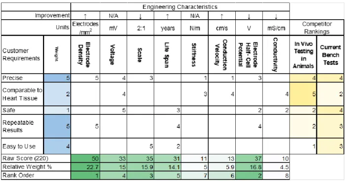
3.3 House of Quality
Table 3: House of Quality of the Left Atrial Model
4.0 Stage Gate Process
4.1 Concept Review
Three concepts were considered:
1.
Inorganic Ballistics Gel with Saline SolutionThis concept involves a mold made of ballistic gel (Humimic Gelatin #1) that is embedded with electrodes and covered in saline solution. Electrical signals are
generated by a grass stimulator and then sent to the mold through wires with electrodes connected at the end. The signals travel from the electrodes across the model with the help of the conductive saline solution on the surface. There will be circuits and an electrical control system such as an Arduino to power and control the electrodes, and these can be manipulated to model different conduction patterns.
2. Organic Gel made Conductive with Salt
This concept is similar to Concept 1, but the mold material is organic gel instead of inorganic. Organic gel allows us to manipulate the conductivity of the whole model, and make it more similar to endocardial/myocardial tissue. The gel itself would conduct the signals throughout the model instead of relying on the saline solution. The main challenge with this concept is determining the appropriate salt to gel ratio since that’s
what dictates the resistivity/conductivity of the model. This concept also relies heavily on electrical control systems in order to simulate necessary electrophysiological features of a healthy and arrhythmic cardiac cycles.
3. Non-conductive Model with Electrode Mesh
A dense electrode mesh would be connected to the surface of a 3D printed PLA model of the atrium, represented by an oval. This concept does not involve the use of any gel, thus the electrode density must compensate for the lack of conductivity in the
surrounding material. The model is not elastic and would not have the same stiffness or tissue compliance as native cardiac tissue. This concept does not involve any testing in terms of surface conductivity but relies on dense circuitry. Programming this model would be more involved than programming one with fewer electrodes. The cost of this concept is also far higher than the other concepts due to the $200 electrode mesh.
4.2 Design Freeze
Concept 2 was deemed the most appropriate out of the three options. Concept 1 was eliminated because the saline solution would not provide enough control of the electrical pathway, and Concept 3 was eliminated because of the high cost and the labor-intensive programming that would be required.
4.3 Design Review
For the design review, the model was discussed and reviewed to ensure validity of rationale behind the circuit design decisions. The voltage value and timing were the two most important factors to be implemented into the model, and were discussed with advisors.
5.0 Description of Final Prototype Design
5.1 Overview
The final prototype design includes an Arduino driving sixteen electrodes which are embedded in a ballistics gel layer. The Arduino is programmed to simulate propagation of current in the heart by stimulating each electrode in series, where each individual electrode outputs a
Humimic Gel
Organic GelPL
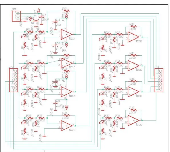
rectangular pulse. Two PCBs include two quad op amps each, which attenuate the Arduino’s 3.3V outputs to 7mV, per Dr. Porterfield’s specifications. The circuit includes a button which allows the user to switch the Arduino output between healthy propagation, arrhythmia, and atrial fibrillation (AFib) modes. The arrhythmic mode includes a small current which stems from a misfiring electrode, and the AFib mode causes electrodes to fire in a nonsense pattern, as cardiac cells do in the human heart.
5.2 Design Justification
The final design outputs the appropriate voltage, can model healthy, arrhythmic, and fibrillating tissue with a change of the button.
5.3 Analysis
5.4 Cost Breakdown
Item Description
ASIN/Product Number
Vendor Unit Quantity Cost URL
Humimic Gelatin #1 SKU: 852844007406 Humimic Medical
1 lb 2 $52.32 https://humim ic.com/produc t/gelatin-1- medical- gelatin-by-the-pound/
Agar Powder 30391-023 Thermo Fisher Scientific
500 g 1 $153 https://www.t hermofisher.c om/order/cat alog/product/ 30391023
NaCl S9888-25G Sigma-Aldrich 25 g 1 $34.90 https://www.s igmaaldrich.co m/programs/r esearch- essentials-products.html ?TablePage=1 02880799 Deionized water
15230-147 Thermo Fisher Scientific
1 L 1 $23.22 https://www.t hermofisher.c om/order/cat alog/product/ 15230147 PLA 3D printed mold Ultimaker NFC PLA - Blue
m/filament/ul timaker-pla.shtml
40 pin MF header
0721205281116 eBay 20pcs 1 $5.99 https://www. ebay.com/p/2 0pcs-Male- Female- Header-1x40- 2-54mm-40- Pin-PCB- Through-Hole- Arduino-and-Pi/802131041 8?iid=2230541 86518
Resistor EAN061663992 7610
Amazon 600
pcs
1 $8.99 https://www.a mazon.com/g p/product/B0 792M83JH/ref =ppx_yo_dt_b _asin_title_o0 3_s00?ie=UTF 8&psc=1 Printed Circuit Board
10189 Bay Area
Circuits
2 1 $104.11 https://store.b ayareacircuits. com/
LED (Red, Green, Yellow)
N/A Amazon 300 1 $8.98 https://www.a
mazon.com/H aitronic- assorted- Prototyping- breadboard-circuitry/dp/B 01MYWS9IW/ ref=sr_1_3?ke ywords=bread board+led&qi d=155900557 7&s=gateway &sr=8-3 Jumper Wires
ulticolored- Breadboard- Dupont- Jumper-Wires/dp/B07 3X7P6N2/ref= sr_1_1_sspa?k eywords=jump er+wires&qid= 1559005872& s=gateway&sr
=8-1-spons&psc=1
Quad Operational Amplifier
5735 Texas
Instruments
4 1 $8.16 http://www.ti.
com/product/ LF347-N
DUE R3 Board
eBay SAM3X8E 1 1 $21.51 https://www.e
bay.com/itm/ DUE-R3-Development -Board- SAM3X8E- 32bit-ARM-Microcontroll er-USB- Cable-for-Arduino/1220 09926802?h ash=item1c6 85bbc92:g:4 osAAOSw~B
1aN-94:sc:USPSF irstClass!954 07!US!-1
5.5 Safety Considerations
filed down. Shock will be prevented by minimizing exposed electronic components. Batteries will also be inspected before use in order to eliminate the danger of shock. A full hazard checklist can be found in Section 10.4: Appendix D.
6.0 Prototype Development
6.1 Model Analyses
Our model was designed after physiology of left atrium of human heart. This means, assuming that electrical signals are initiated in the Sinoatrial node of the heart and as time progresses, such signals travel down the atrium and toward the apex of the heart. This is what a regular heartbeat would look like. During AFib, signals do not necessarily follow the pattern described above.
In patients who suffer from Atrial Fibrillation, due to faulty tissue in the atria, signals get generated randomly and out of order. They may vary in voltage from regular signals or may have irregular timing patterns as well as locations.
This model is designed to simulate regular as well as irregular timing and location of electrical signals in human’s left atrium.
6.2 Evolution of Prototypes
Prototype 1:Initially, Humimic ballistics gel was mixed with sodium chloride to serve as the conductive gel catheter interface. This gel was tested using a multimeter and four AAA batteries as a power source. The conductivity of the gel was far too low to achieve the desired current propagation.
Prototype 2:
Porcine gel was used in a layer on top of a ballistics gel layer. The porcine gel was mixed with sodium chloride in order to enhance its conductive properties. The ballistics gel was cut into a rectangle, then aluminum foil was used to create a makeshift mold that the porcine gel was poured into. An Arduino was used to drive one electrode, which was used with one ground electrode to test the conductivity of the gel. Porcine gel’s electrical properties were extremely inconsistent.
Prototype 3:
Porcine heart tissue was used with the same Arduino setup as the previous porcine gel sample. The heart tissue was tested without the presence of saline. The porcine heart tissue did not
Prototype 4:
the Arduino IDE. ±15V pins from an Elvis board were used to power the op-amp rails. The gel was not homogeneous and never set entirely.
Prototype 5:
The same polyethylene gel recipe was used, though sodium azide and polyethylene powder were eliminated. Additionally, the agarose gel was boiled during manufacturing, which
increased consistency and helped with mixing. This gel was poured into a petri dish to set, and was also tested still in this circular Petri dish mold. A button was added to the breadboard and to the Arduino code, which allows the user to switch between healthy propagation and atrial fibrillation. Four 9V batteries were used to power the op amp rails. The agarose gel’s electrical properties were not sufficiently consistent.
Prototype 6:
The ballistics gel layer is housed inside of a 3D printed mold which includes a slot for a 40-pin header at the bottom of it. The female side of the header is at the underside, which allows for connections to the Arduino output circuit. The male pins are exposed out the top of the
ballistics gel. A PCB of the Arduino output circuit was made, not including the button. A function generator was used to power the op amp rails, due to insufficient battery voltage.
7.0 IQ/OQ/PQ
Installation Qualification (IQ):
Electrode Assembly
Electrode connection to control system Gel conductivity: 3-6.25 mS/cm
Gel stiffness Control system
Material Source Part Number Link
DUE R3 Board eBay SAM3X8E https://www.ebay.co
m/itm/DUE-R3- Development-Board- SAM3X8E-32bit- ARM-Microcontroller- USB-Cable-for-Arduino/1220099268 02?hash=item1c685b bc92:g:4osAAOSw~
B1aN-94:sc:USPSFirstClas s!95407!US!-1
PCB Bay Area Circuits 10189 https://store.bayareaci
rcuits.com/
om/gp/product/B0792 M83JH/ref=ppx_yo_dt _b_asin_title_o03_s00 ?ie=UTF8&psc=1
Capacitors Amazon HGY-1K-X https://www.amazon.
com/Hilitchi-150-Pcs- 10000pF-Capacitor-Assortment/dp/B073 TVJV4W/ref=sr_1_1_ sspa?keywords=cap acitors&qid=1559006 663&s=gateway&sr= 8-1-spons&psc=1
Jumper Wires Amazon ALLUS J7011 https://www.amazon.c
om/Multicolored- Breadboard-Dupont-
Jumper-Wires/dp/B073X7P6N2 /ref=sr_1_1_sspa?key words=jumper+wires& qid=1559005872&s=ga
teway&sr=8-1-spons&psc=1
Operation Qualification (OQ):
Voltage Range: 5-7 mV
Electrode Lifespan: 1000 cycles Precision: < 9 mm2 electrode density Timing: Early firing node should fire
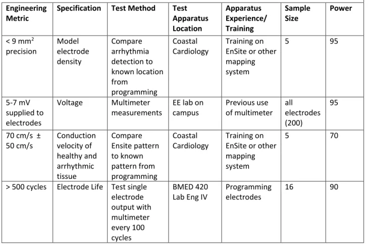
7.1 Design of Experiments
Materials testing is performed using electrical equipment found in on-campus labs. Voltage and conductivity was tested using function generators and multimeters.
Table 4: Design of Experiments of Left Atrial Model
Engineering Metric
Specification Test Method Test Apparatus Location Apparatus Experience/ Training Sample Size Power
< 9 mm2 precision Model electrode density Compare arrhythmia detection to known location from programming Coastal Cardiology Training on EnSite or other mapping system
5 95
5-7 mV supplied to electrodes
Voltage Multimeter measurements
EE lab on campus Previous use of multimeter all electrodes (200) 95
70 cm/s ± 50 cm/s Conduction velocity of healthy and arrhythmic tissue Compare Ensite pattern to known pattern from programming Coastal Cardiology Training on EnSite or other mapping system
5 70
> 500 cycles Electrode Life Test single electrode output with multimeter every 100 cycles BMED 420 Lab Eng IV
Programming electrodes
16 90
7.2 Verification and Validation
Voltage Range:Spatial Voltage Test
1. Header is placed into gel sample
2. One pin of header is supplied with 6.9 mV 3. Another pin is grounded across the sample
4. Voltage measurements are taken every 0.1” across the header 5. Data is graphed in Excel to find mathematical model
Timing Test
1. Header is placed into conductive gel sample
2. ‘afib.ino’ code is uploaded to DUE board, controlling 16 electrodes 3. Another electrode is grounded at the end of the sample per MPI
4. Oscilloscope measurements are taken at point A between electrodes 11 and 12, and point B between electrodes 8 and 9.
6. Use cursors to ensure that point A peaks twice and point B peaks once
Electrode Lifespan:
Repeated Cycles Test
1. ‘propagate_button16.ino’ code is uploaded to DUE board, controlling 16 electrodes 2. Voltage output is measured on each electrode
3. The code is run until each electrode has fired 500 times 4. Voltage output is measured again on each electrode 5. The voltage measurements are compared and evaluated
Precision:
Spatial Resolution Test**
1. Headers are placed into the 3D printed mold
2. Jump wires are plugged into the header at the bottom of the mold (equally spaced with 4 slots between each wire)
3. The ground wire is plugged in at the end of each header, 3 slots from the last firing electrode
4. Each pin is manufactured to be 0.1” apart, but will be verified by using a ruler
7.3 Manufacturing Process Instructions
Step Instructions Photo(s)
1 Melt 103g of Humimic ballistics gel in a glass beaker on a hot plate at 150°C until it has completely liquified
2 Fix two 40 pin M-F headers in the slots of the 3D printed mold with the M pins pointing up & the F pins flush with the bottom of the mold; place the assembly in a glass dish
3 Pour the Humimic ballistics gel into the 3D printed mold, avoiding the header pins and evenly distributing the gel
5 Measure out 2 g of agar powder, 0.5 g of NaCl, 100 mL of deionized water and combine in one beaker
7 Cover the beaker with a layer of aluminum foil and mix with a magnetic stir bar at 800 rpm until the flakes of agar are dissolved and the mixture is homogeneous (about 10 minutes)
8 Pour the agarose gel into the mold, covering the Humimic gel and embedding the header pins
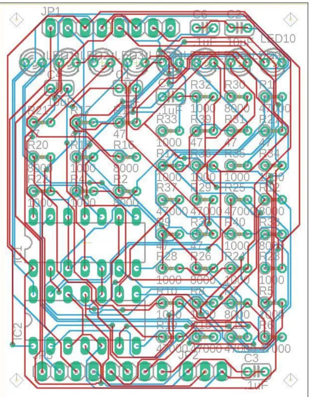
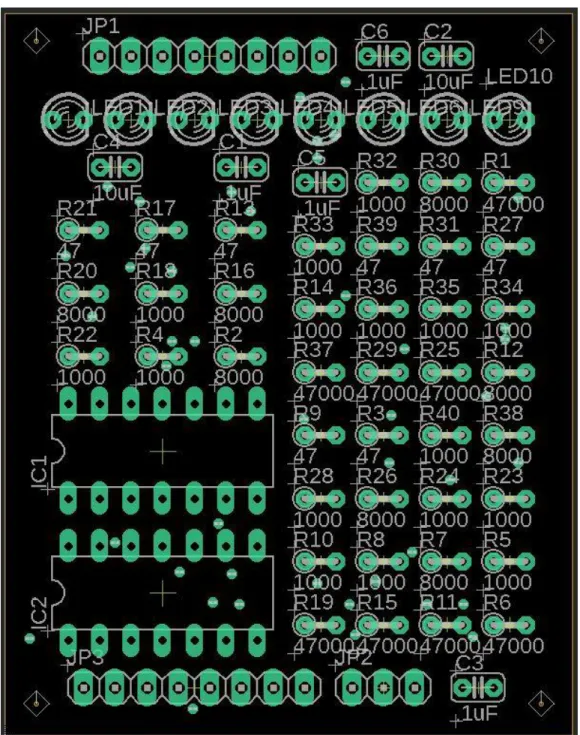
10 Outsource PCB manufacturing using Eagle board file ‘sr proj 2 quad op amps cap.brd’
11 Solder all components to the PCB per the PCB schematic
13 Connect 2 jumper wires (1 per header) to the outermost slot on the other side of the header as a ground
(There should be 3 gaps between this ground and the nearest wire)
14 Plug the other ends of the 2 ground wires into the ground plate on the small breadboard
15 Wire the button and 3 indicator LEDs on a breadboard per the button schematic
16 Program the DUE R3 outputs: use Arduino file ‘propagate_button16.ino’
17 Wire corresponding PCB inputs to DUE R3 Board digital I/O ports per PCB board schematic
18 Ensure op amps rails are powered by 18V supplies and DUE R3 board is powered via USB connection
MPI step Deviation from MPI Completed By Signature Date
1 Humimic gel was melted in microwave at full power for 7 minutes, stirring halfway
Sarah Porrello Sarah Porrello 5/24/19
Gel was pulled out of mold, re-melted on a hot plate, and re-cast
Sarah Porrello Sarah Porrello 5/27/19
2, 3, 4 N/A Sarah Porrello Sarah Porrello 5/24/19
5 N/A Borna Sobati Borna Sobati 5/27/19
6 Beaker covered with tin foil to prevent convective cooling
Borna Sobati Borna Sobati 5/27/19
7 N/A Tess Pate Tess Pate 5/27/19
8 Only about half of the agarose gel was poured into the mold
Sarah Porrello Sarah Porrello 5/27/19
9, 10, 11, 12, 13, 14, 15, 16, 17, 18
N/A Tess Pate Tess Pate 5/27/19
8.0 Conclusions and Recommendations
8.1 Recommendations
● Prior to pouring the conductive gel, it’s recommended to wait for about 5 minutes after taking the beaker off the hot plate before pouring into the mold. This way temperature of conductive gel would be low enough (~65°C) so that mold would not get deformed.
● It is more efficient and less time consuming to increase temperature of the hot plate to temperatures higher than 150°C temporarily while mixing the agar gel. If chosen to take this additional step, be careful not to let the gel “boil” and “foam” since it can overflow out of the beaker.
seconds. This way, uniform soldering and minimal damage to the board/components may be expected.
8.2 Conclusions
The final prototype is a useful visual model of healthy, pre-AFib, and AFib conditions of the heart. LEDs that correspond with each electrode allow the user to view the conduction pattern of each mode, and a button toggles between them.
The conductive gel did not allow for a uniform conductivity and results were inconclusive. However, according to a study done on electrical properties of phantom gels, it was concluded that such gels cannot mimic the living human tissue in low frequencies [12]. Therefore, as a future step, we would recommend using a high frequency signal instead of direct current. It is important to test the voltage in the final prototype using mapping catheters that are available to the electrophysiologist, which was not available to us. To overcome this setback, one can potentially use an ECG device for a basic and
relatively accurate recording of the signals
9.0 Acknowledgements
10.0 Appendices
10.1 Appendix A: References
[1] Abbott. (n.d.). Advisor™ HD Grid Mapping Catheter, Sensor Enabled™ | Abbott Cardiovascular. Retrieved from
https://www.cardiovascular.abbott/us/en/hcp/products/electrophysiology/advisor-hd-grid.html [2] American Heart Association. (2016, July 31). Why Atrial Fibrillation (AF or AFib) Matters. Retrieved from https://www.heart.org/en/health-topics/atrial-fibrillation/why-atrial-fibrillation-af-or-afib-matters
[3] Atrial fibrillation ablation. (2018, March 24). Retrieved from https://www.mayoclinic.org/tests-procedures/atrial-fibrillation-ablation/about/pac-20384969
[4] BioSense Webster. (n.d.). CARTO® 3 System - Advanced 3D Cardiac Mapping. Retrieved from https://www.biosensewebster.com/products/carto-3/lasso-eco-catheter.aspx
[5] Boston Scientific. (n.d.). INTELLAMAP ORION™. Retrieved from
http://www.bostonscientific.com/content/gwc/en-US/products/catheters--mapping/orion.html [6] Go, A. S., Hylek, E. M., Phillips, K. A., Chang, Y., Henault, L. E., Selby, J. V., & Singer, D. E. (2001, May 09). Prevalence of diagnosed atrial fibrillation in adults: National implications for rhythm management and stroke prevention: The AnTicoagulation and Risk Factors in Atrial Fibrillation (ATRIA) Study. Retrieved from https://www.ncbi.nlm.nih.gov/pubmed/11343485/ [7] Khaykin, Y., Morillo, C. A., Skanes, A. C., McCracken, A., Humphries, K., & Kerr, C. R. (2007, July 30). Cost comparison of catheter ablation and medical therapy in atrial fibrillation. Retrieved from https://www.ncbi.nlm.nih.gov/pubmed/17666065
[8] MA, A. (2015, December 23). One in eight patients require repeat catheter ablation for AF within 1 year. Retrieved from
https://www.healio.com/cardiology/arrhythmia- disorders/news/online/{b6fcf051-e863-4e16-96f8-7d1ad3c617b4}/one-in-eight-patients-require-repeat-catheter-ablation-for-af-within-1-year
[9] Medtronic. (n.d.). Cardiac Ablation Products for Atrial Fibrillation - Achieve Advance Mapping Catheter. Retrieved from
https://www.medtronic.com/us-en/healthcare- professionals/products/cardiac-rhythm/ablation-atrial-fibrillation/achieve-advance-mapping-catheter.html
[10] Nguyen, D. T., Gerstenfeld, E. P., Tzou, W. S., Jurgens, P. T., Zheng, L., Schuller, J., . . . Sauer, W. H. (2017, May 31). Radiofrequency Ablation Using an Open Irrigated Electrode Cooled With Half-Normal Saline. Retrieved from
http://electrophysiology.onlinejacc.org/content/early/2017/05/24/j.jacep.2017.03.006 [11] Tmr. (2018, January 11). TMR. Retrieved from
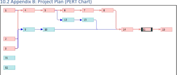
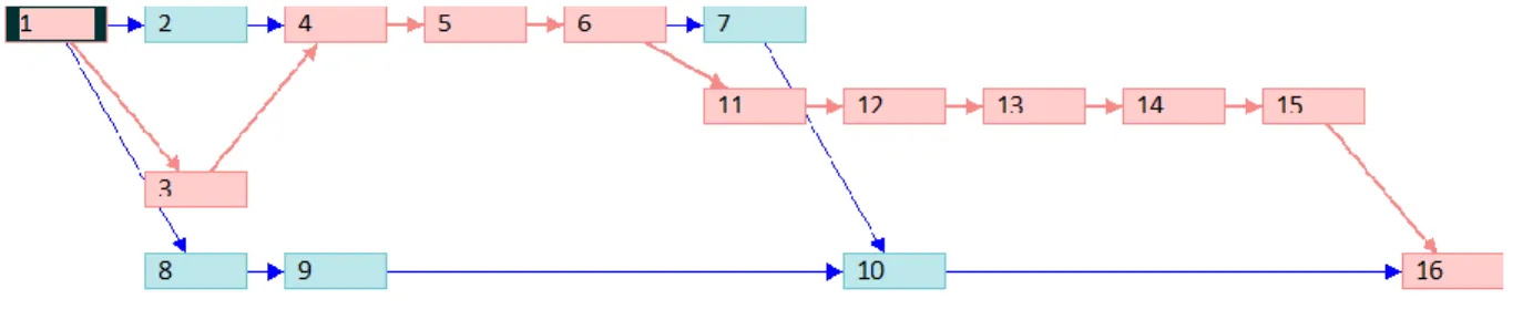
10.2 Appendix B: Project Plan (PERT Chart)
Figure 1. Initial PERT Chart for Winter Quarter
Figure 3. Test and Manufacturing PERT Chart for Spring Quarter
10.3 Appendix C: CAD Drawings
Figure 5. TinkerCAD Schematic of Button Breadboard
10.4 Appendix D: FMEA, Hazard & Risk Assessment
Failure Modes Effect Analysis:
Design Hazard Checklist:
Team: Left Atrial Model Advisor: Dr. Chris Porterfield
1. Will any part of the design create hazardous revolving, reciprocating, running, shearing, punching, pressing, squeezing, drawing, cutting, rolling, mixing or similar action,
including pinch points and sheer points? Y
2. Can any part of the design undergo high accelerations/decelerations? N
3. Will the system have any large moving masses or large forces? N
4. Will the system produce a projectile? N
5. Would it be possible for the system to fall under gravity creating injury? N
6. Will a user be exposed to overhanging weights as part of the design? N
7. Will the system have any sharp edges? Y
8. Will any part of the electrical systems not be grounded? N
9. Will there be any large batteries or electrical voltage in the system above 40 V? N
10. Will there be any stored energy in the system such as batteries, flywheels, hanging weights or pressurized fluids? Y
11. Will there be any explosive or flammable liquids, gases, or dust fuel as part of the system? N
12. Will the user of the design be required to exert any abnormal effort or physical posture during the use of the design? N
13. Will there be any materials known to be hazardous to humans involved in either the design or the manufacturing of the design? N
14. Can the system generate high levels of noise? N
15. Will the device/system be exposed to extreme environmental conditions such as fog, humidity, cold, high temperatures, etc? N
16. Is it possible for the system to be used in an unsafe manner? N
17. Will there be any other potential hazards not listed above? N
Description of Hazard
Planned Corrective Action
Planned Date Actual
High melting point of the medical gel
(200F-270F)
Use of gloves and tools that will help prevent direct contact
with skin
02/12/2019 5/24/19
Possibly sharp edges of electrodes used in
the model
Electrodes are to be handled with caution using clamping tools
02/12/2019 5/26/19
Use of batteries (potential for unexpected heating)
The device is not to be left unattended
02/12/2019 5/13/19
Burn risk while soldering
Use of gloves and prior training
Lead exposure risk from contact with solder joints on PCB
Washing hands after touching any soldered components
5/26/19 5/26/19
10.5 Appendix E: Pugh Chart
Concept 1: Humimic gel covered in saline Concept 2: Organic gel with salt dissolved
Concept 3: Humimic gel with enough wires to meet accuracy requirements without being conductive
10.6 Appendix F: Vendor Information, Specifications, and Data Sheets
- Humimic Medical: Gelatin #1
SDS: https://humimic.com/material-safety-data-sheet-msds/ - Porcine Gel
SDS:https://www.sigmaaldrich.com/content/dam/sigma-aldrich/docs/Sigma/Product_Information_Sheet/2/g2500pis.pdf - Polyethylene powder
SDS:https://www.sigmaaldrich.com/MSDS/MSDS/DisplayMSDSPage.do?country=US&l anguage=en&productNumber=332119&brand=ALDRICH&PageToGoToURL=https%3A %2F%2Fwww.sigmaaldrich.com%2Fcatalog%2Fproduct%2Faldrich%2F332119%3Flan g%3Den
- Sodium Azide SDS:
https://www.fishersci.com/store/msds?partNumber=S227I1&productDescription=SODIU M+AZIDE+GRAN+PURIF+1+KG&vendorId=VN00033897&countryCode=US&language =en
- Agar SDS:
https://www.fishersci.com/shop/msdsproxy?productName=AC400400050&productDesc ription=AGAR%252C+POWDER+5KG&catNo=AC400400050&vendorId=VN00032119 &storeId=10652
- PCB
10.8 Appendix H: DHF
Engineering Specifications/Product Specification Customer
Requirement
Engineering
Metric Specification Rationale
As precise as the
probe < 9 mm2 precision
Model electrode
size Must test probe accuracy Surface electrical
characteristics of the
left atrium 5-7 mV
Model electrode voltage
Function with mapping catheter
Ease of Use Button Response Conduction velocity
and pattern of healthy
and arrhythmic tissue 70 cm/s ± 50 cm/s
Programmability of electrodes
Model healthy and arrhythmic conduction patterns
Conductivity mimics cardiac tissue
0.16 S/m (murine left ventricular)
Ion content of the gel
Conductivity of murine myocardium
DHR/LHR
Step Number
Process Responsible Party
Signature Date
(MM/DD/YYYY)
1 Melt 103g of Humimic ballistics gel in a glass beaker on a hot plate at 150°C until it has completely liquified
Sarah Porrello Sarah Porrello 5/23/2019
2 Fix two 40 pin M-F headers in the slots of the 3D printed mold with the M pins pointing up & the F pins flush with the bottom of the mold; place the assembly in a glass dish
Sarah Porrello Sarah Porrello 5/23/2019
3 Pour the Humimic ballistics gel into the 3D
printed mold, avoiding the header pins and evenly distributing the gel
4 Allow ballistics gel to cool completely and remove any gel that may be stuck to the pins
Sarah Porello Sarah Porrello 5/27/2019
5 Measure out 2 g of agar powder, 0.5 g of NaCl, 100 mL of deionized water and combine in one beaker
Borna Sobati Borna Sobati 5/27/2019
6 Heat the mixture on a hot plate to 95°C
Borna Sobati Borna Sobati 5/27/2019
7 Cover the beaker with a layer of aluminum foil and mix with a
magnetic stir bar at 800 rpm until the flakes of agar are dissolved and the mixture is
homogeneous (about 10 minutes)
Borna Sobati Borna Sobati 5/27/2019
8 Pour the agarose gel into the mold, covering the Humimic gel and embedding the header pins
Sarah Porello Sarah Porrello 5/27/2019
9 Refrigerate the gels for 15 minutes to allow the agarose gel to set
Sarah Porello Sarah Porrello 5/27/2019
10 Outsource PCB manufacturing using Eagle board file ‘sr proj 2 quad op amps cap.brd’
11 Solder all components to the PCB per the PCB schematic
Sarah Porello Sarah Porrello 5/27/2019
12 Connect 16 jumper wires to the headers and solder the other ends to the PCB output pads per PCB board schematic
(8 wires per header, 4 gaps are placed between each wire, with the first wire plugged into the outermost slot)
Borna Sobati Borna Sobati 5/27/2019
13 Connect 2 jumper wires (1 per header) to the outermost slot on the other side of the header as a ground (There should be 3 gaps between this ground and the nearest wire)
Sarah Porello Sarah Porrello 5/27/2019
14 Plug the other ends of the 2 ground wires into the ground plate on the small breadboard
Sarah Porello Sarah Porrello 5/27/2019
15 Wire the button and 3 indicator LEDs on a breadboard per the button schematic
Sarah Porello Sarah Porrello 5/27/2019
16 Program the DUE R3 outputs: use Arduino file
‘propagate_button16.i no’
Tess Pate Tess Pate 5/27/2019
17 Wire corresponding PCB inputs to DUE R3 Board digital I/O ports
per PCB board schematic
18 Ensure op amps rails are powered by 18V supplies and DUE R3 board is powered via USB connection
Borna Sobati Borna Sobati 5/27/2019
10.9 Appendix I: Raw Data
Testing Electrode Voltage:1.8 Porcine, 15mL water, No NaCl distance from source
[in] voltage [mV]
0.1 2.9
0.2 3.6
0.3 11.7
0.4 8.6
0.5 14.3
0.6 22.2
0.7 19.5
0.8 17.8
0.9 17.1
1 20.4
1.1 11.1
1.2 6.1
1.3 4.2
1.4 30.1
1.5 5.1
1.6 12.3
1.8 Porcine, 15mL water, 0.2g NaCl
distance from source voltage [mV]
0.1 1.4
0.2 1.2
0.3 4.5
0.4 3.6
0.5 9.5
0.6 1.7
0.7 1.3
0.8 6.5
0.9 5.2
1 2.1
1.1 3.9
1.2 7.6
1.3 9.4
1.4 6.1
1.5 13.3
1.6 6
1.8 Porcine, 15mL water, 0.015g NaCl (with header)
distance from source voltage [mV]
0.1 57
0.2 37
0.3 33.9
0.4 99
0.5 26
0.6 25.6
0.7 23.3
0.8 28.8
0.9 28.9
1 21.9
1.1 22.6
1.2 25
1.3 24
1.4 20
1.5 26.5
1.6 25.1
1.8 Porcine, 15mL water, 0.015g NaCl (without header)
distance from source
voltage trial 2 [mV]
0.1 102
0.2 103
0.3 99
0.4 6
0.5 45
0.6 99
0.7 97
0.8 196
0.9 89
1 25
1.1 47
1.2 60
1.3 89
1.4 140
1.5 75
1.6 79
Porcine Myocardium distance from
source voltage [mV]
0.1 -50
0.2 -215
0.3 -35
0.4 87
0.5 -140
0.6 -30
0.7 -180
0.8 -150
0.9 30
1 -200
1.1 6
1.2 15
1.3 -130
1.4 188
1.5 -53
1.6 -14
Agarose Gel (2 wt% agar, 0.2wt% NaCl)
Distance From Source
(in) Potential (mV)
0.1 42
0.2 42
0.3 56
0.4 55
0.5 42
0.6 41
0.7 45
0.8 38
0.9 40
1 50
1.1 41
1.2 42
1.3 36
1.4 42
1.5 60
1.6 60
1.7 52
1.8 50
Figure 8. Eagle PCB Layout to be used for component placement
The code used for simulation:
propagate_button16.ino
const int button = 5; //button pin
int frequency = 100; //Set frequency in Hertz
int buttonPushCounter = 0; // counter for button presses int buttonState = 0; //Read button status
int lastButtonState = 0; int afib = 1; //type of rhythm
int red = 2; //indicator LED: ON if afib and during button push int yellow = 3;
double delayTime = 90 ; //Pulse length double butdelayTime = 1000 ; //button delay void setup() { pinMode(button, INPUT); pinMode(6, OUTPUT); pinMode(7, OUTPUT); pinMode(8, OUTPUT); pinMode(9, OUTPUT); pinMode(10, OUTPUT); pinMode(11, OUTPUT); pinMode(12, OUTPUT); pinMode(13, OUTPUT); pinMode(22, OUTPUT); pinMode(23, OUTPUT); pinMode(24, OUTPUT); pinMode(25, OUTPUT); pinMode(26, OUTPUT); pinMode(27, OUTPUT); pinMode(28, OUTPUT); pinMode(29, OUTPUT); pinMode(red, OUTPUT); pinMode(yellow, OUTPUT); pinMode(green, OUTPUT); } void loop() {
buttonState = digitalRead(button); //if button is pressed, switch afib state
if ((buttonState != lastButtonState) &&(buttonState == 1)) {afib++;
if(afib>2) afib =0; }
//propagate if 0, pre-afib if 1, afib if 2 //begin propagate code
if (afib == 0) {
digitalWrite(green, HIGH); //indicates healthy digitalWrite(yellow, LOW); //
digitalWrite(red, LOW); // digitalWrite(6, LOW); digitalWrite(7, LOW); digitalWrite(8, LOW); digitalWrite(9, LOW); digitalWrite(10, LOW); digitalWrite(11, LOW); digitalWrite(12, LOW);
digitalWrite(8, LOW); digitalWrite(9, LOW); digitalWrite(10, LOW); digitalWrite(11, LOW); digitalWrite(12, LOW); digitalWrite(13, LOW); digitalWrite(22, HIGH); digitalWrite(23, HIGH); digitalWrite(24, LOW); digitalWrite(25, LOW); digitalWrite(26, LOW); digitalWrite(27, LOW); digitalWrite(28, LOW); digitalWrite(29, LOW); delay(delayTime); digitalWrite(6, LOW); digitalWrite(7, LOW); digitalWrite(8, LOW); digitalWrite(9, LOW); digitalWrite(10, LOW); digitalWrite(11, LOW); digitalWrite(12, LOW); digitalWrite(13, LOW); digitalWrite(22, HIGH); digitalWrite(23, LOW); digitalWrite(24, LOW); digitalWrite(25, LOW); digitalWrite(26, LOW); digitalWrite(27, LOW); digitalWrite(28, LOW); digitalWrite(29, LOW); delay(delayTime); }
//begin afib condition if (afib == 1) {
digitalWrite(green, LOW); //
digitalWrite(yellow, HIGH); //indicates pre-afib digitalWrite(red, LOW); //
digitalWrite(6, LOW); digitalWrite(7, LOW); digitalWrite(8, LOW); digitalWrite(9, LOW); digitalWrite(10, LOW); digitalWrite(11, LOW); digitalWrite(12, LOW);
digitalWrite(22, LOW); digitalWrite(23, LOW); digitalWrite(24, LOW); digitalWrite(25, LOW); digitalWrite(26, HIGH); digitalWrite(27, HIGH); digitalWrite(28, LOW); digitalWrite(29, LOW); delay(delayTime); digitalWrite(6, LOW); digitalWrite(7, LOW); digitalWrite(8, HIGH); digitalWrite(9, HIGH); digitalWrite(10, LOW); digitalWrite(11, LOW); digitalWrite(12, LOW); digitalWrite(13, LOW); digitalWrite(22, LOW); digitalWrite(23, LOW); digitalWrite(24, LOW); digitalWrite(25, HIGH); digitalWrite(26, HIGH); digitalWrite(27, LOW); digitalWrite(28, LOW); digitalWrite(29, LOW); delay(delayTime); digitalWrite(6, LOW); digitalWrite(7, HIGH); digitalWrite(8, HIGH); digitalWrite(9, LOW); digitalWrite(10, LOW); digitalWrite(11, LOW); digitalWrite(12, LOW); digitalWrite(13, LOW); digitalWrite(22, LOW); digitalWrite(23, LOW); digitalWrite(24, HIGH); digitalWrite(25, HIGH); digitalWrite(26, LOW); digitalWrite(27, LOW);
digitalWrite(12, LOW); digitalWrite(13, LOW); digitalWrite(22, HIGH); digitalWrite(23, HIGH); digitalWrite(24, LOW); digitalWrite(25, LOW); digitalWrite(26, HIGH); digitalWrite(27, LOW); digitalWrite(28, LOW); digitalWrite(29, LOW); delay(delayTime); digitalWrite(6, LOW); digitalWrite(7, LOW); digitalWrite(8, LOW); digitalWrite(9, LOW); digitalWrite(10, HIGH); digitalWrite(11, LOW); digitalWrite(12, LOW); digitalWrite(13, LOW); digitalWrite(22, HIGH); digitalWrite(23, LOW); digitalWrite(24, LOW); digitalWrite(25, HIGH); digitalWrite(26, LOW); digitalWrite(27, LOW); digitalWrite(28, LOW); digitalWrite(29, LOW); delay(delayTime); }
//begin afib condition if (afib == 2) {
digitalWrite(green, LOW); // digitalWrite(yellow, LOW); //
digitalWrite(red, HIGH); //indicates afib digitalWrite(6, HIGH); digitalWrite(7, LOW); digitalWrite(8, LOW); digitalWrite(9, LOW); digitalWrite(10, LOW); digitalWrite(11, LOW); digitalWrite(12, LOW);
digitalWrite(24, LOW); digitalWrite(25, HIGH); digitalWrite(26, LOW); digitalWrite(27, LOW); digitalWrite(28, HIGH); digitalWrite(29, LOW); delay(delayTime); digitalWrite(6, HIGH); digitalWrite(7, LOW); digitalWrite(8, LOW); digitalWrite(9, LOW); digitalWrite(10, LOW); digitalWrite(11, LOW); digitalWrite(12, LOW); digitalWrite(13, LOW); digitalWrite(22, HIGH); digitalWrite(23, LOW); digitalWrite(24, LOW); digitalWrite(25, LOW); digitalWrite(26, LOW); digitalWrite(27, HIGH); digitalWrite(28, LOW); digitalWrite(29, HIGH); delay(delayTime);
} }
IQ/OQ
see Section 7.0
Bill of Materials
see Appendix G
FMEA