Data models
Types of data models
High-level
or
conceptual data models
o
Entity-Relationship model
o
object data model
low-level
or
physical data models
Representational
or
implementation
data
models
or
record-based data models
.
o
Relational model
o
network model
o
hierarchical model
DATA MODELS
A
data model
—a collection of concepts that can be used to
describe the structure of a database—provides the necessary
means to achieve this abstraction
A structure that demonstrates all the required features of the parts
of the real world, which is of interest to the users of the information in
the model.
Representation and reflection of the real world (Universe of
Discourse).
A set of concepts that can be used to describe the structure of a
database: the data types, relationships, constraints, semantics and
operational behavior.
It is a tool for data abstraction
A collection of tools for describing
data
data relationships
data semantics
Some of the data models are :
High-level
or
conceptual data models
o
Entity-Relationship model
o
object data model
low-level
or
physical data models
Representational
or
implementation
data
models
or
record-based data models.
o
Relational model
o
network model
High-level
or
conceptual data models
Conceptual data models use concepts such as entities,
attributes, and relationships.
An
entity
• represents a real-world object or concept, such as an
employee or a project from the mini-world that is
described in the database.
An
attribute
• represents some property of interest that further
describes an entity, such as the employee’s name or
salary.
A
relationship
Physical (low-level, internal) data models:
•Provide concepts that describe details of how
data is stored in the computer. These are
usually specified in an ad-hoc manner through
DBMS design and administration manuals
Implementation (representational) data
models:
• Provide concepts that fall between the above
two, used by many commercial DBMS
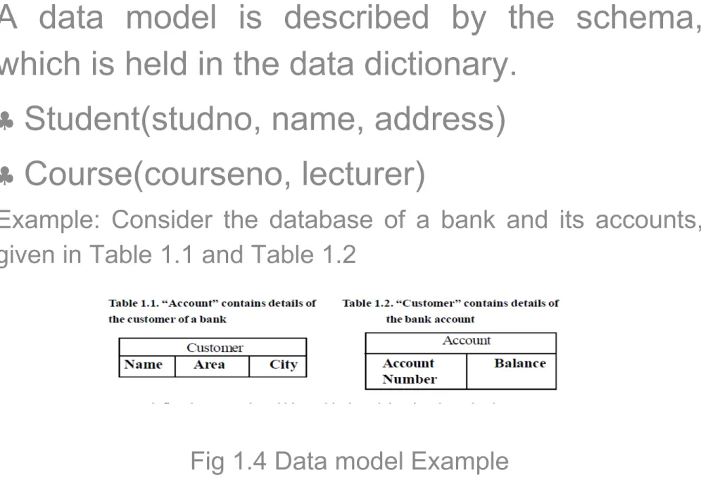
A data model is described by the schema,
which is held in the data dictionary.
Student(studno, name, address)
Course(courseno, lecturer)
Example: Consider the database of a bank and its accounts,
given in Table 1.1 and Table 1.2
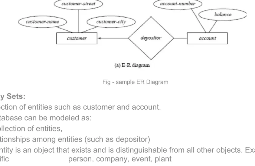
ENTITY- RELATIONSHIP MODEL – example for conceptual data model
E.R. diagram which consists of entity sets and relationship sets.
Fig - sample ER Diagram
Entity Sets:
Collection of entities such as customer and account. A database can be modeled as:
a collection of entities,
relationships among entities (such as depositor)
An entity is an object that exists and is distinguishable from all other objects. Example: specific person, company, event, plant
Attributes:
An entity is represented by a set of attributes, that is, descriptive properties possessed by all members of an entity set.
Example:
Customer = (customer-name, social-security, customer-street, customer-city) Account= (account-number, balance)
Domain
• The set of permitted values for each attribute
Attribute types
• Simple and composite attributes.
Single-valued and multi-valued attributes.
Null attributes.
Derived attributes.
Keys:
A super key of an entity set is a set of one or more attributes whose values uniquely determine each entity.
A candidate key of an entity set is a minimal super key.
social-security is candidate key of customer
account-number is candidate key of account
Although several candidate keys may exist, one of the candidate keys is selected to be the primary key.
The combination of primary keys of the participating entity sets forms a candidate key of a relationship set.
It must consider the mapping cardinality and the semantics of the relationship set when selecting the primary key.
E-R Diagram Components
Rectangles represent entity sets.
Ellipses represent attributes.
Diamonds represent relationship sets.
Lines link attributes to entity sets and entity sets to relationship sets.
Double ellipses represent multivalued attributes.
Dashed ellipses denote derived attributes.
Primary key attributes are underlined.
Weak Entity Set
An entity set that does not have a primary key is referred to as a weak entity set. The existence of a weak entity set depends on the existence of a strong entity set; it must relate to the strong set via a one-to-many relationship set.
The discriminator (or partial key) of a weak entity set is the set of attributes that distinguishes among all the entities of a weak entity set. The primary key of a weak entity set is formed by the primary key of the strong entity set on which the weak entity set is existence dependent, plus the weak entity set’s discriminator.
Specialization
This is a Top-down design process as shown in Figure in which; we designate sub-groupings within an entity set that are distinctive from other entities in the set. These sub-groupings become lower-level entity sets that have attributes or participate in relationships that do not apply to the higher-level entity set. Depicted by a triangle component labeled ISA (i.e., savings-account “is an” account)
Generalization:
A bottom-up design process – combine a number
of entity sets that share the same features into a
higher-level entity set.
Specialization and generalization are simple
inversions of each other; they are represented in
an E-R diagram in the same way.
Attribute Inheritance – a lower-level entity set
inherits all the attributes and relationship
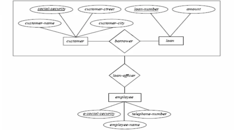
Aggregation:
Figure shows the need for aggregation since it has two relationship sets. The second relationship set is necessary because loan customers may be advised by a loan-officer.
Relationship sets borrower and loan-officer represent the same information
Eliminate this redundancy via aggregation as shown in Figure 1.8 Points in Aggregation
Treat relationship as an abstract entity.
Allows relationships between relationships.
Abstraction of relationship into new entity.
Without introducing redundancy, the following diagram represents that:
A customer takes out a loan
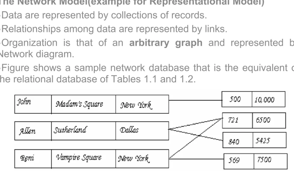
The Network Model(example for Representational Model)
Data are represented by collections of records.
Relationships among data are represented by links.
Organization is that of an
arbitrary graph
and represented by
Network diagram.
Figure shows a sample network database that is the equivalent of
the relational database of Tables 1.1 and 1.2.
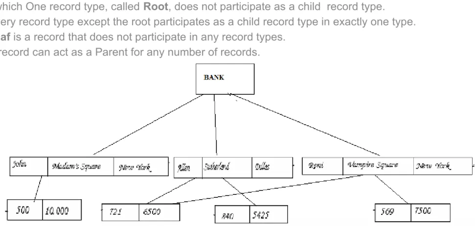
The Hierarchical Model
Similar to the network model and the concepts are derived from the earlier systems Information Management System and System-200.
Organization of the records is as a collection of trees, rather than arbitrary graphs.
In the hierarchical model, a Schema represented by a Hierarchical Diagram as shown in Figure 1.4 in which One record type, called Root, does not participate as a child record type.
Every record type except the root participates as a child record type in exactly one type.
Leaf is a record that does not participate in any record types.
A record can act as a Parent for any number of records.
Fig 1.5 Sample Hierarchical Model