ETSI GS NFV 001
V1.1.1
(2013-10)
Network Functions Virtualisation (NFV);
Use Cases
Disclaimer
This document has been produced and approved by the Network Functions Virtualisation (NFV) ETSI Industry Specification Group (ISG) and represents the views of those members who participated in this ISG.
It does not necessarily represent the views of the entire ETSI membership.
Reference DGS/NFV-009
Keywords NFV, use case
ETSI
650 Route des Lucioles
F-06921 Sophia Antipolis Cedex - FRANCE Tel.: +33 4 92 94 42 00 Fax: +33 4 93 65 47 16
Siret N° 348 623 562 00017 - NAF 742 C Association à but non lucratif enregistrée à la
Sous-Préfecture de Grasse (06) N° 7803/88
Important notice
Individual copies of the present document can be downloaded from: http://www.etsi.org
The present document may be made available in more than one electronic version or in print. In any case of existing or perceived difference in contents between such versions, the reference version is the Portable Document Format (PDF). In case of dispute, the reference shall be the printing on ETSI printers of the PDF version kept on a specific network drive
within ETSI Secretariat.
Users of the present document should be aware that the document may be subject to revision or change of status. Information on the current status of this and other ETSI documents is available at http://portal.etsi.org/tb/status/status.asp
If you find errors in the present document, please send your comment to one of the following services: http://portal.etsi.org/chaircor/ETSI_support.asp
Copyright Notification
No part may be reproduced except as authorized by written permission. The copyright and the foregoing restriction extend to reproduction in all media.
© European Telecommunications Standards Institute 2013. All rights reserved.
DECTTM, PLUGTESTSTM, UMTSTM and the ETSI logo are Trade Marks of ETSI registered for the benefit of its Members. 3GPPTM and LTE™ are Trade Marks of ETSI registered for the benefit of its Members and
of the 3GPP Organizational Partners.
Contents
Intellectual Property Rights ... 5
Foreword ... 5
1 Scope
... 6
2 References
... 6
2.1 Normative references ... 6
2.2 Informative references ... 6
3 Definitions
and
abbreviations
... 7
3.1 Definitions ... 7
3.2 Abbreviations ... 7
4 Overview
... 9
5
Use Case #1: Network Functions Virtualisation Infrastructure as a Service... 10
5.1 Motivation ... 10
5.2 Description ... 11
5.3 Virtualisation Target... 13
5.4 Coexistence of Virtualised and Non-Virtualised Network Functions ... 14
5.5 Problem description/Issues ... 14
6
Use Case #2: Virtual Network Function as a Service (VNFaaS) ... 15
6.1 Motivation ... 15
6.2 Description ... 16
6.2.1 Virtualisation of the CPE (vE-CPE) - Functional description ... 16
6.2.2 Virtualisation of the PE (vPE) - Functional description ... 18
6.3 Virtualisation Target... 18
6.4 Coexistence of Virtualised and Non-Virtualised Network Functions ... 19
6.4.1 Partial Virtualisation ... 19
6.4.2 Mixed Virtualisation Scenarios ... 19
6.5 Problem description/Issues ... 20
7
Use Case #3: Virtual Network Platform as a Service (VNPaaS) ... 21
7.1 Motivation ... 21
7.2 Description ... 21
7.3 Virtualisation Target... 23
7.4 Coexistence of Virtualised and Non-Virtualised Network Functions ... 23
7.5 Problem description/Issues ... 23
8
Use Case #4: VNF Forwarding Graphs ... 23
8.1 Motivation ... 23
8.2 Description ... 24
8.3 Virtualisation Target... 27
8.4 Coexistence of Virtualised and Non-Virtualised Network Functions ... 27
8.5 Problem description/Issues ... 27
9
Use Case #5: Virtualisation of Mobile Core Network and IMS... 28
9.1 Motivation ... 28
9.2 Description ... 28
9.3 Virtualisation Target... 30
9.4 Coexistence of Virtualised and Non-Virtualised Network Functions ... 30
9.5 Problem description/Issues ... 32
10
Use Case #6: Virtualisation of Mobile base station ... 33
10.1 Motivation ... 33
10.2 Description ... 33
10.3 Virtualisation Target... 34
10.4 Coexistence of Virtualised and Non-Virtualised Network Functions ... 35
11
Use Case #7: Virtualisation of the Home Environment ... 36
11.1 Motivation ... 36
11.2 Description ... 37
11.3 Virtualisation Target... 38
11.4 Coexistence of Virtualised and Non-Virtualised Network Functions ... 39
11.5 Problem description/Issues ... 41
12
Use Case #8: Virtualisation of CDNs (vCDN)... 42
12.1 Motivation ... 42
12.2 Description ... 42
12.3 Virtualisation Target... 43
12.4 Coexistence of Virtualised and Non-Virtualised Network Functions ... 44
12.5 Problem description/Issues ... 44
13
Use Case #9: Fixed Access Network Functions Virtualisation ... 44
13.1 Motivation ... 44
13.2 Description ... 45
13.2.1 Challenges... 46
13.3 Virtualisation Target... 47
13.4 Coexistence of Virtualised and Non-virtualised Network Functions ... 48
13.5 Problem description/Issues ... 49
Intellectual Property Rights
IPRs essential or potentially essential to the present document may have been declared to ETSI. The information pertaining to these essential IPRs, if any, is publicly available for ETSI members and non-members, and can be found in ETSI SR 000 314: "Intellectual Property Rights (IPRs); Essential, or potentially Essential, IPRs notified to ETSI in respect of ETSI standards", which is available from the ETSI Secretariat. Latest updates are available on the ETSI Web server (http://ipr.etsi.org).
Pursuant to the ETSI IPR Policy, no investigation, including IPR searches, has been carried out by ETSI. No guarantee can be given as to the existence of other IPRs not referenced in ETSI SR 000 314 (or the updates on the ETSI Web server) which are, or may be, or may become, essential to the present document.
Foreword
This Group Specification (GS) has been produced by ETSI Industry Specification Group (ISG) Network Functions Virtualisation (NFV).
1 Scope
The scope of the present document is to describe use cases of interest for Network Functions Virtualisation (NFV).
2 References
References are either specific (identified by date of publication and/or edition number or version number) or
non-specific. For specific references, only the cited version applies. For non-specific references, the latest version of the referenced document (including any amendments) applies.
Referenced documents which are not found to be publicly available in the expected location might be found at
http://docbox.etsi.org/Reference.
NOTE: While any hyperlinks included in this clause were valid at the time of publication, ETSI cannot guarantee their long term validity.
2.1 Normative
references
The following referenced documents are necessary for the application of the present document.
[1] ETSI GS NFV 003: "Network Functions Virtualisation (NFV); Terminology for Main Concepts in NFV".
2.2 Informative
references
The following referenced documents are not necessary for the application of the present document but they assist the user with regard to a particular subject area.
[i.1] NFV White paper: "Network Functions Virtualisation, An Introduction, Benefits, Enablers, Challenges & Call for Action. Issue 1".
NOTE: Available at http://portal.etsi.org/NFV/NFV_White_Paper.pdf.
[i.2] Recommendation ITU-T Y.3510 (05-2013):"Cloud Computing Infrastructure Requirements". [i.3] NIST SP 800-146, Badger et al.: "Draft Cloud Computing Synopsis and recommendations",
(May 2011), pg. 7-2.
[i.4] Recommendation ITU-T Y.3501 (05-2013): "Cloud computing framework and high level requirements".
[i.5] Recommendation ITU-T Y.3501 (05-2013): "Cloud computing framework and high level requirements", appendix I.3 "NaaS general use case", pg 15.
[i.6] Black's Law Dictionary.
[i.7] ATIS Telecom Glossary.
NOTE: Available online at http://www.atis.org/glossary/definition.aspx?id=1828.
[i.8] IETF RFC 4026 Andersson, L. March 2005: "Provider Provisioned Virtual Private Network (VPN) Terminology".
NOTE: Available at http://tools.ietf.org/html/rfc4026.
3 Definitions
and
abbreviations
3.1 Definitions
For the purposes of the present document, the terms and definitions given in GS NFV 003 [1] apply.
3.2 Abbreviations
For the purposes of the present document, the following abbreviations apply: 3GPP™ 3rd Generation Partnership Project
AAA Authentication, Authorization and Accounting ADSL Asymmetric digital subscriber line
ALG Application Level Gateway
AN Access Node
API Application Programming Interface
APN Access Point Name
APP Application
AR Access Router
ARPU Average Revenue Per User
AS Application Server
ASP Application Service Provider
BBU Base Band Unit
BGP Border Gateway Protocol BNG Broadband Network Gateway BPF Band Pass Filter
BRAS Broadband Remote Access Server
BS Base Station
BSS Business Support System
BYOD Bring Your Own Device CAPEX Capital Expenses
CCITI Centralized Corporate IT Infrastructure CDN Content Delivery Network
CO Central Office
CoMP Coordinated Multipoint
COTS Custom Off The Shelf
CPE Customer Premises Equipment CPRI Common Public Radio Interface CPU Central Processing Unit
C-RAN Cloud Radio Access Network CSC Cloud Service Customer CSCF Call Session Control Function CSP Cloud Service Provider
DC Data Centre
DHCP Dynamic Host Configuration Protocol DLNA Digital Living Network Alliance
DNS Domain Name System
DPI Deep Packet Inspection DPU Distribution Point Unit
DSL Digital Subscriber Line
DSLAM Digital subscriber line access multiplexer
DSP Digital Signal Processing
DUP Duplexer
EMS Element Management System
eNodeB Evolved Node B EPC Evolved Packet Core EPG Electronic Program Guide EPS Evolved Packet System ETTx Ethernet To-The x
EVPN Ethernet Virtual Private Network
FG Forwarding Graph
FTTcab Fibre To The Cabinet
FTTdp Fibre To The Distribution Point
FTTH Fibre To The Home
FTTP Fibre To The Premises
FW Firewall
GGSN Gateway GPRS Support Node GPRS General Packet Radio Service GUI Graphical User Interface GW Gateway
HD High Definition
HDD Hard Disk Drive
HPA High Power Amplifier HSS Home Subscriber Server HTTP Hypertext Transfer Protocol HW Hardware IaaS Infrastructure as a Service
I-CSCF Interrogating-Call Session Control Function IMS IP Multimedia Subsystem
IP Internet Protocol
IPS Intrusion Prevention System
IPTV Internet Protocol Television
ISP Internet Service Provider
IT Information Technology
ITU International Telecommunication Union
ITU-T International Telecommunication Union - Telecommunication
LAN Local Area Network
LNA Low Noise Amplifier
LTE Lone-Term Evolution
MAC Media Access Control MDU Multi Dwelling Unit
MGCF Media Gateway Control Function MIMO Multi Input Multi Output
MME Mobility Management Entity NaaS Network as a Service NAT Network Address Translation
NF Network Function
NFV Network Functions Virtualisation
NFVI Network Functions Virtualisation Infrastructure
NFVIaaS Network Functions Virtualisation Infrastructure as a Service NFVI-PoP Network Functions Virtualisation Infrastructure Point of Presence NG-FW Next Generation Firewall
NIC Network Interface Controller
NIST National Institute of Standards and Technology NPVR Network Personal Video Recorder
NSP Network Service Provider
OAM Operation, Administration and Maintenance OCS Online Charging System
OFCS Offline Charging System OLT Optical Line Termination ONT Optical Network Terminal ONU Optical Network Unit OPEX Operational Expenses OSS Operations Support System
OTT Over-The-Top
PaaS Platform as a Service
PCRF Policy and Charging Control Function P-CSCF Proxy-Call Session Control Function PDCP Packet Data Convergence Protocol PDN Packet Data Network
PGW Packet Gateway PHY Physical PoP Network Point of Presence
PPPoE Point-to-Point Protocol Over Ethernet
PPVPNS Provider Provisioned Virtual Private Network Service PVR Personal Video Recorder
QoE Quality of Experience QoS Quality of Service
RAM Random Access Memory
RAN Radio Access Network RGW Residential Gateway
RLC Radio Link Control
RRC Radio Resource Control SaaS Software as a Service
S-CSCF Serving-Call Session Control Function SDN Software Defined Networks
SDR Soft Defined Radio
SGSN Serving GPRS Support Node
SGW Serving Gateway
SLA Service Level Agreement
SNMP Simple Network Management Protocol SON Self Organizing Networks
STB Setup Box
SW Software TCO Total Cost of Ownership
TSTV Time-Shift TV
TV Television
UE User Equipment
UI User Interface
uPnP Universal Plug-and-Play VDI Video Device Interface
VDSL Very-high-bit-rate digital subscriber line
vE-CPE Virtual Enterprise-Customer Premises Equipment VLAN Virtual Local Access Network
VM Virtual Machine
VNF Virtual Network Function VNF FG VNF Forwarding Graph
VNFaaS Virtual Network Function as a Service VNIC Virtual Network Interface Controller VNPaaS Virtual Network Platform as a Service
VOD Video On Demand
VOIP Voice Over Internet Protocol (IP) vPE Virtual Provider Edge (Router) VPLS Virtual Private LAN Service VPN Virtual Private Network
WAN Wide Area Network
Wi-Fi Wireless LAN
WiMAX® Worldwide Interoperability for Microwave Access WOC WAN Optimization Controller
4 Overview
Network Functions Virtualisation (NFV) aims to transform the way that network operators architect networks by evolving standard IT virtualisation technology to consolidate many network equipment types onto industry standard high volume servers, switches and storage, which could be located in a variety of NFVI-PoPs including datacentres, network nodes and in end user premises.
In principle, all network functions and nodes may be considered for virtualisation and should be enabled by standards. The purpose of the present document is to identify and describe a first set of service models and high level use cases which represent, in the view of NFV ISG member companies, important service models and initial fields of application for NFV, and which span the scope of technical challenges being addressed by the NFV ISG.
A detailed description of the NFV objectives is contained in [i.1]. In summary, these high-level objectives of NFV are:
• Rapid service innovation through software-based deployment and operationalization of network functions and end-to-end services.
• Improved operational efficiencies resulting from common automation and operating procedures.
• Reduced power usage achieved by migrating workloads and powering down unused hardware.
• Standardized and open interfaces between network functions and their management entities so that such decoupled network elements can be provided by different players.
• Greater flexibility in assigning VNFs to hardware.
• Improved capital efficiencies compared with dedicated hardware implementations.
The present document introduces different models by which Cloud Computing Services are typically offered to consumers and some applications in specific network and market segments. The order of the use cases follows this concept. First to be listed are use cases describing service models and then the one use cases referring to the different network and market segments. The order is not intended to give any priority amongst use cases.
The specific context of a "role" or "actor" in each use case is for further study.
This initial set of use cases is not intended to be exhaustive and may be updated as new use cases are identified as being helpful in addressing the technical and business challenges of NFV. These service models and use cases are intended to clarify the roles and interactions of the various types of commercial entities acting in a marketplace for services delivered via these VNFs. These actors include commercial entities/roles such as Service Providers, Enterprises, Consumers, etc. The fields of application provide high level descriptions of areas where the industry believes NFV technologies can initially be applied and which are representative of the business and technical challenges to be overcome.
The service models and use cases described in the present document are intended to provide a commercial and technical context that is expected to be useful for discussions on technical requirements and architectures in further documents to be developed by the NFV ISG. Other Industry forums may also find these service models and use cases helpful as they consider implementation options for virtualisation of the network functions they have previously standardized. The present document is not intended to provide detailed behavioural modelling of components of the NFV framework. Future documents describing components of the NFV framework may develop additional use cases to illustrate the behaviour of those NFV framework components; those components of the NFV framework, however, should be validated against the service models and fields of application described in the present document for consistency.
5
Use Case #1: Network Functions Virtualisation
Infrastructure as a Service
5.1 Motivation
Many Service Providers offer cloud computing services in addition to network services (acting as Cloud Service Providers- CSPs when doing so). Cloud computing services require physical compute, network and storage resources Recommendations ITU-T Y.3510 [i.2] and Recommendation ITU-T Y.3501 [i.4]. Virtualised Network Functions require physical compute network and storage resources. Resource pooling Recommendations ITU-T Y.3510 [i.2] and Recommendation ITU-T Y.3501 [i.4] is an essential characteristic of Cloud Computing in the NIST (National Institute of Standards and Technology) definition. Resource pooling is also a desired characteristic of the NFV Infrastructure. It would be desirable to pool the compute network and storage resources such that common infrastructure elements could support a Service Provider in delivering cloud computing services as well as network services.
NIST defines several deployment models NIST SP 800-146 [i.3], pg 2-2 for cloud computing services including private cloud, community cloud, public cloud and hybrid cloud. These differ primarily in which entities are authorized to use the cloud computing services - the entity owning the cloud computing infrastructure (private cloud), the general public (public cloud), a specific group (community cloud) or some combination of these (hybrid cloud). A Service Provider implementing network services using VNF instances running on common infrastructure elements with cloud computing services should consider the appropriate deployment model to meet their business objectives. Private cloud deployment models may be a common approach for many Service Providers.
In order to meet network service performance objectives (e.g. latency, reliability), or regulatory requirements, it may be desirable for a Service Provider to be able to run VNF instances inside an NFV Infrastructure (including infrastructure elements common with cloud computing services) which is operated as a service by a different Service Provider. Few Service Providers have the resources to deploy, and maintain physical infrastructure around the globe; and yet their consumer and enterprise customers demand global services. The ability to remotely deploy and run Virtualised network functions inside an NFV Infrastructure provided as a service by another Service Provider permits a Service Provider to more efficiently service its global customers. The ability for a Service Provider to offer its NFV Infrastructure as a Service (e.g. to other Service Providers) enables an additional commercial service offer (in addition to a Service Providers existing catalog of network services that may be supported by VNFs) to directly support, and accelerate, the deployment of NFV Infrastructure. The NFVI may also be offered as a Service from one department to another within a single Service Provider.
5.2 Description
Cloud Computing Services are typically offered to consumers in one of three service models NIST SP 800-146 [i.3], pg 2-1 - Infrastructure as a Service (IaaS), Platform as a Service (PaaS) or Software as a Service (SaaS). In particular, NIST SP 800-146 [i.3], pg 2-1 defines the IaaS as the capability to offer to consumers processing, storage and fundamental computing resources. The consumer can then use the provided resources to run specific applications on which he has the control. He does not control the underlying infrastructure.
Some literature [i.5] also refers to a capability to offer network connectivity services as Network as a Service (NaaS), but no reference was found for a standardized definition of this term. One application for NaaS appears to be the on demand creation of network connectivity between CSPs and CSCs, though it may also refer to the on demand creation of network connectivity within data centres or between the computing nodes of a CSPs infrastructure.
Service is a word with multiple meanings that are generally related to the act of doing something useful for another entity, often for a fee or as part of some commercial transaction [i.6], or as a functionality enabled by a service provider for the consumer of that service [i.7]; in the context of computing, software and service oriented networks. However, it can also refer to a function that is performed by software for another (software) entity [i.7]. The NFV Infrastructure can be considered as providing the capability or functionality of providing an environment in which Virtualised network functions can execute. The NFVI shall provide compute capabilities comparable to an IaaS cloud computing service as a run time execution environment as well as support the dynamic network connectivity services that may be considered as comparable to NaaS. This use case provides an approach to mapping the Cloud Computing Service Models IaaS and NaaS as elements within the Network Function Virtualisation Infrastructure when it is provided as a service. Further study may identify elements of IaaS and NaaS that are not required for some NFVI purposes or instantiation, but for now it seems appropriate to assume that these service models can be used to provide some of the capabilities that a NFVI may deliver, as shown in the Diagram of Figure 1. In the case of a Service Provider using their own NFVI/cloud computing infrastructure in a private cloud deployment model, the services provided by the NFVI are provided to software entities i.e. VNFs.
Figure 1: Mapping IaaS and NaaS within the NFV Infrastructure
The resources to be pooled between these services are the physical network, storage and compute resources. In the NFV model these would be considered as the Compute, Hypervisor and Network domains of the Network Function
Virtualisation Infrastructure. In the Cloud Computing model, these resources would be considered as elements
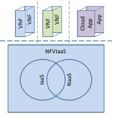
supporting IaaS or NaaS cloud computing service models. The PaaS and SaaS cloud computing service models provide software based capabilities that have to run over some infrastructure (perhaps the same infrastructure that may be offering IaaS or NaaS service). The computing nodes of the NFV Infrastructure will be located in NFVI-PoPs such as central offices, outside plant, specialized pods or embedded in other network equipment or mobile devices. The physical location of the infrastructure is largely irrelevant for cloud computing services, but many network services have some degree of location dependence. The resource pooling concept includes a notion of multi-tenancy - where the same pool of resources supports multiple applications from different administrative or trust domains. Figure 2 illustrates an NFVIaaS supporting both cloud computing applications as well as VNF instances from different administrative domains.
Figure 2: NFVIaaS Multi-tenant Support
Where a Service Provider (#2) runs VNF instances on the NFVI/cloud infrastructure of another Service Provider (#1), this would be relying a on some sort of commercial service agreement between them. Figure 3 is intended to illustrate this example. Service Provider #1 will require that only authorized entities should be able to load and operate VNF instances on its NFV Infrastructure. The set of resources (e.g. compute / hypervisor /network capacity, bindings to network terminations, etc.) that Service Provider #1 make available to Service Provider #2 would be constrained. Service Provider #2 shall be able to integrate its VNF instances running on Service Provider#1's NFV Infrastructure into an end to end network service instance along with VNF instances running on its own NFV infrastructure. Figure 3 is intended to illustrate this example.
Figure 3: Example of Administrative Domain #2 running VNFs on the NFV Infrastructure provided by Administrative Domain #1
5.3 Virtualisation
Target
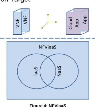
Figure 4: NFVIaaS
A target of virtualisation is for the NFVI to be available as an execution environment for software entities. The NFVIaaS should support those infrastructure services necessary to support the operational life cycle of VNF instances. The NFVIaaS should also be capable of supporting dynamic creation of connectivity (e.g. NaaS) between virtual and physical network termination points (e.g. VNF instances, physical network terminations). The NFVIaaS should also be capable of supporting generic computing loads ("cloud apps") on an IaaS basis. The services supplied by the NFVIaaS should be deliverable within one administrative domain and/or across administrative boundaries.
Service Provider #1 has motivations to make available NFV Infrastructure as a Service, within capacity constraints and other limitations because this commercial offer can help drive the deployment of the NFV Infrastructure. Service Provider #1 has to choose the terms of the commercial offer proposed and the specific resources made available, but these commercial details should not be subject to standardization. One target for standardization should be the metadata description of the types of NFVI resources that can be made available through the NFVIaaS.
Service Provider #2 may be interested to run a VNF instance on the NFV Infrastructure of Service Provider #1 in addition to its own NFV Infrastructure to improve resiliency. The NFV Infrastructures of the two Service Providers are distinct and independent. Failures on one NFV Infrastructure should be independent of failures on the NFV
infrastructure of the other. Running redundant VNF instances on independent NFV Infrastructure should permit Service Provider #2 to offer a higher resiliency service than it could using just its own NFV Infrastructure (while virtualisation typically converts infrastructure failures into capacity reductions). Virtualisation should also target mechanisms to support failure recoveries across NFV Infrastructures managed by different domains and mechanisms to validate the independence of NFV Infrastructures managed by different administrative domains.
Service Provider #2 may be interested to run a VNF instance on the NFV Infrastructure of Service Provider #1 in order to improve the customer experience by reducing latency. Latency can be reduced by placing selected network functions close to the consumer of that network service. A CDN service reduces latency (and reduces cost) for content consumers by caching that content closer to the consumer. Certain EPC functions may reduce latency, and improve throughput for the mobile consumer if they can be located closer to the RAN. The virtualisation target should also target mechanisms to measure latency in particular deployments as well as planning tools to predict expected latency in planned
deployments.
Service Provider #2 may be interested to run a VNF instance on the NFV Infrastructure of Service Provider #1 in order to comply with regulatory requirements. Some regulatory authorities place geographic restrictions on the location of storage and processing of certain kinds of consumer information. The NFV Infrastructure of Service Provider #1, if located within the appropriate geographic region, may prove convenient for the storage and processing of such consumer information. The virtualisation should also target mechanisms to identify and restrict the locations where information is stored and processed.
5.4
Coexistence of Virtualised and Non-Virtualised Network
Functions
Non Virtualised network functions would exist in parallel with the VNFs in this use case, but are not expected to raise any issue particular to this use case.
Virtualised Network Functions from multiple Service Providers may coexist within the same NFV infrastructure. The NFV infrastructure shall provide the appropriate isolation between the resources allocated to the different service providers. VNF instances failures or resource demands from one service Provider should not be permitted to degrade the operation of other Service Provider's VNF instances.
There will be a need to implement IP, Ethernet and other packet forwarding mechanisms to interconnect to and manage VNF instances in another Service Provider's Infrastructure as well as connect to users connected to another Service Provider's access network.
5.5 Problem
description/Issues
The NFVIaaS model should permit a Service Provider to fulfil, assure and bill for services delivered to end users across NFVIs that are independently administered, and therefore requires accurate monitoring and reporting of status of NFVI resources allocated to the VNF instances of a particular Service Provider. The management and orchestration of VNF instances into a network service instance through a VNF Forwarding Graph should be possible when the VNF instance is running on the NFV Infrastructure of another service provider. Appropriate authentication and authorization mechanism will be required to support orchestration of VNF instances in these cases. The NFVI should provide
mechanisms to restrict access such that only authorized VNF instances are permitted to execute on the NFVI. The NFVI should provide mechanisms such that VNF instances can only access the physical and virtual network terminations to which their access is authorized.
There is a need to support measurement of SLA [1] related parameters in a commercial NFVIaaS offer between Service Providers.
There is a need to support failure notification and diagnostics in a commercial NFVIaaS offer between Service Providers.
6
Use Case #2: Virtual Network Function as a Service
(VNFaaS)
6.1 Motivation
Today's enterprises are deploying multiple services at the edge of branch offices. Many enterprises find the cost of a dedicated standalone appliance per-feature prohibitive, inflexible, slow to install and difficult to maintain. In other implementations, the functionality may be provided by an integrated access router which may be limited in feature set. As the enterprise continues to evolve, more services and applications migrate to the enterprise DC or public clouds, forcing a change in the way enterprise networks are built. In addition, mobility and BYOD become standard resulting in even more required services such as data leakage prevention.
Faced with a big required investment, many enterprises are looking for outsource alternatives. These alternatives may include the virtualisation of the Enterprise CPE (Access Router) into the operator's network.
These virtualisation trends, combined with virtualisation capabilities made possible by NFV, represent a big business opportunity for service providers trying to meet the growing customer requirements while controlling cost, and are faced with increased OPEX and CAPEX pressure. Traditional IP routers based on custom hardware and software are amongst the most capital-intensive portions of service provider infrastructure. Provider Edge (PE) routers run out of control plane resources before they run out of data plane resources and virtualisation of control plane functions improves scalability.
Substantial saving may be possible by moving routing functionality from purpose-built routers to equivalent
functionality implemented in COTS hardware environments providing cloud computing capabilities such as the NFVI. Rather than the Enterprise investing its own capital in deployment of networking infrastructure, the service provider may be able to provide advanced networking features as a measured service NIST SP 800-146 [i.3], pg 2-1 on an expense basis. The service provider could operate a VNF instance using its NFVI which provides the functionality required to implement the enterprise CPE and potentially another VNF instance for the control plane of the PE router improving its scalability. Making the VNF functionality available to the enterprise as a service is comparable to the cloud computing notion of Software as a Service.
NIST SP 800-146 [i.3], pg 2-1 defines Software as a Service (SaaS) as the possibility for the consumer to use software applications running on a cloud infrastructure. The consumer can manage the application only from a configuration perspective and cannot control the underlying infrastructure.
In this Virtualised enterprise services example, the VNF is the service provider's application. The Enterprise is the consumer of the service. The Enterprise is not managing or controlling the NFVI or the VNF. The Enterprise as a consumer of the VNFaaS does not have to invest additional capital in advanced networking features provided via the control plane; rather it can obtain them on an expense basis from the Service Provider as needed. The Service Provider can scale the NFVI resources allocated to the VNF instance in response to increasing usage of the VNF.
NIST SP 800-146 [i.3], pg 5-4 and 5-5 identified the following advantages of the SaaS model, which should also apply in the case of a VNFaaS:
• Modest software tool footprint for the enterprise to access the service
• Efficient use of software licenses
• Centralized management and data
6.2 Description
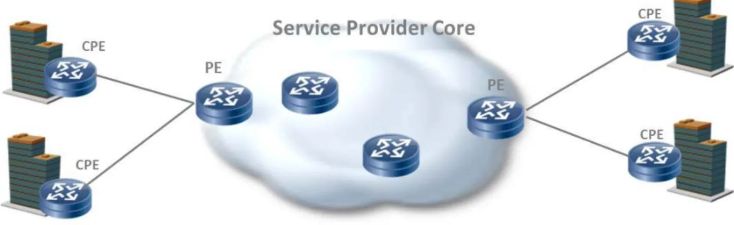
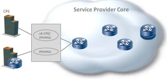
Pre-NFV service provider networks include a Provider Edge (PE) router at the edge of the core, facing the Customer Premises Equipment (CPE) device as illustrated in Figure 5. There are two business models; either the service provider or the enterprise can own and operate the CPE.
Figure 5: Service Provider without virtualisation of the enterprise
Virtualisation of the enterprise may include:
• Virtualisation of the CPE functions (vE-CPE) in the service provider cloud.
• Virtualisation of the PE functions (vPE) where the virtual network services functions and core-facing PE functions can be executed in the service provider cloud.
These two steps are independent and may be deployed separately. PE routers are typically shared by a high number of customers, whereas a CPE router is used exclusively by a single customer. Thus, economies of scale that can be gained from CPE virtualisation are significantly greater compared to PE virtualisation. It is likely, therefore, that virtualisation of the CPE will take place first, providing the largest benefit for both the Enterprise users and the Service providers. Virtualisation of the PE may be done at a later stage to complete the transition to a fully Virtualised NFV solution. In some architectures, the vE-CPE and vPE may be controlled by a centralized controller following the SDN architecture principles and standards (e.g. OpenFlow).
The Service Provider is responsible for deploying, configuring, updating and managing the operation of the VNF instance to provide the expected service level (SLA) for subscribers to the VNFaaS.
6.2.1
Virtualisation of the CPE (vE-CPE) - Functional description
The vE-CPE solution enhances the enterprise network by replacing appliances with NFV compliant Virtualised solutions located at either the enterprise cloud or the operator of the NFV framework. Services provided by the vE-CPE may include a router providing QoS and other high-end services such as L7 stateful firewall, intrusion detection and prevention and more. Application accelerators are also deployed either as standalone appliances or as router integrated services.
Figure 6 provides a view of a typical large enterprise comprising headquarters facilities with a centralized corporate IT infrastructure and multiple branches connected to one another and to the enterprise headquarter. The vE-CPE
Figure 6: vE-CPE Location Examples
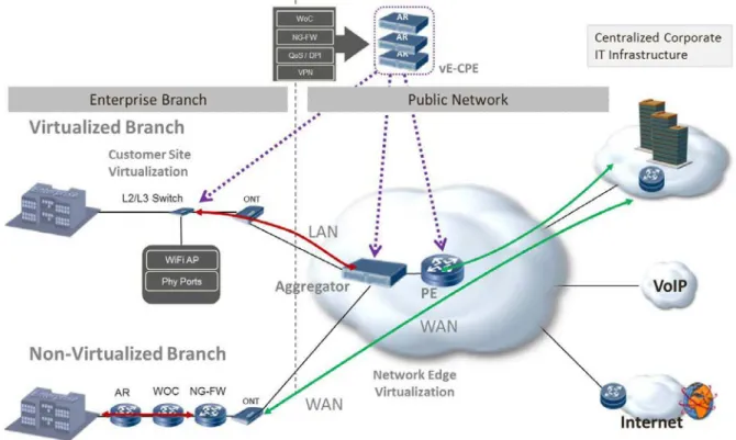
Figure 7 presents the functionality re-distribution as a result of the virtualisation of the CPE. The enterprise local traffic is handled by a local L2 or L3 switch providing physical connectivity (and possibly further functionality), and the enterprise LAN is extended to the Operator NFV Network located CPE. Example functionality provided by the vE-CPE in Figure 7 includes routing, VPN termination, QoS support, DPI, NG-FW and a WOC (WAN Optimization Controller). We contrast the case of a non-virtualised customer site served by a non-virtualised CPE, and that of a site served by a vE-CPE. The dotted purple lines indicate where this vE-CPE functionality may be located.
6.2.2
Virtualisation of the PE (vPE) - Functional description
Virtualisation of core routers may not be feasible in the short term due to high throughput requirements, but the virtualisation of the PE Router is more likely with additional benefits of providing scalability of Provider provisioned virtual private network services through the dynamic resizing or allocation of virtual resources. The Provider
Provisioned Virtual Private Network Service (PPVPNS) functions in the vPE include layer 3 IP VPNs, layer 2 VPLS, EVPN, pseudo-wire services and more [i.8].
Figure 8: Virtualisation of CPE, Virtual Network Services and PE core facing functions
The virtual PE functions could:
• Be integrated in a single Virtual Machine (vPE in Figure 8), implementing the equivalent functionality of a single physical PE or a subset of a physical PE for scalability and performance.
• Be split across a core set of functions (vPEcore in Figure 8) and virtual network services functions (NSFs) that include or do not include CPE functions (PPVPNS and vE-CPE/PPVPNS).
6.3 Virtualisation
Target
There are a number of Network Functions typically deployed today within Enterprise networks as dedicated hardware infrastructure where it may, in the future, be appropriate for a Service Provider to deliver on a VNFaaS basis to the Enterprise. These Enterprise network functions include:
1) AR - Enterprise Access Router / Enterprise CPE 2) PE - Provider Edge Router
3) FW - Enterprise Firewall 4) NG-FW - Enterprise NG-FW
5) WOC - Enterprise WAN optimization Controller 6) DPI - Deep Packet Inspection (Appliance or a function)
7) IPS - Intrusion Prevention System and other Security appliances 8) Network Performance Monitoring
6.4
Coexistence of Virtualised and Non-Virtualised Network
Functions
6.4.1 Partial
Virtualisation
A combined virtualisation model consists of providing virtual network services functions with or without CPE functions (vE-CPE/ PPVPNS vs. PPVPNS in Figure 9) while maintaining the core facing PE functions on the PE. This
decomposition scenario of the PE may be limited to single vendor implementations as interworking would require standardization of the interface between the PE and the provider provisioned virtual private network services (may not be in scope of NFV).
Figure 9: Virtualisation of services while maintaining core facing functions on real PE
6.4.2
Mixed Virtualisation Scenarios
Figure 10 demonstrates co-existence and interoperability of Virtualised and non-Virtualised Enterprise CPE functions. In the upper depicted branch, the vE-CPE is implemented in the operator NFV Network. The Branch local traffic extends into the operator network and terminates at the vE-CPE.
The lower branch represents a legacy solution provided by non-Virtualised appliances. In this case, the Enterprise local traffic stays within the branch.
Seamless connectivity is maintained between Virtualised branches and non-Virtualised branches deploying legacy WAN solutions.
6.5 Problem
description/Issues
It is estimated that a large number of Virtualised devices need to be supported at the edge, requiring enormous amount of resources from the NFVI. The vPE should be able to independently scale on the data plane and control plane to support very large forwarding tables and a very large number of flows. Compared with Virtualised Home solutions, virtualisation of the enterprise requires significantly lower number of VNFs, each with a much larger number of flows and performance requirements.
To contain the cost and scale, a large number of Virtualised devices need to be integrated on limited number of CPUs. With the expected growths of enterprise bandwidth requirements, the required bandwidth per CPU may exceed today's CPU capabilities.
To achieve the performance targets, the virtual PE functions could:
• Be integrated in a single virtual machine
• Be split across a core set of functions and virtual network services functions
The vPE should be able to scale dynamically to support a very large forwarding table and a very large number of flows . To achieve the scaling, the vPE can be scaled, for example, by:
• Modifying infrastructure resources allocated to a vPE instance, e.g. increasing memory
• Creating additional instances of the vPE
In the Virtualised environment, the responsibility for ensuring proper behaviour of every scenario is in the hand of the VNFaaS Provider. The vE-CPE and vPE are required to support a large number of applications and services driven by the enterprise dynamics. In addition, there will be many topologies and network configurations during the migration from current to Virtualised networks.
Both the VNFaaS Provider and the user share the responsibility for managing the vPE and vE-CPE. Enterprise users expect to manage and configure their CPE devices and manage SW versions when upgrades happen, even when they are Virtualised and provided as a service.
VNFaaS is introducing a single-point of failure as operations internal to the Enterprise that are dependent on the CPE, may not work properly upon loss of network connectivity. The challenge is to guarantee service continuity at the enterprise during network or access link failure (to match current network behaviour).
Should the vPE and vE-CPE be controlled by a centralized controller following the SDN architecture principles and standards, reliable connectivity between the controller and the virtual devices, regardless of their location is crucial. The Virtualised environment needs to guarantee complete isolation among users. Extending the Enterprise LAN into the operator network requires a VPN between the enterprise and the operator virtual function. Special considerations are needed for protecting the enterprise data and configuration files.
Providing VNFaaS as a measured service requires usage measurement metrics and infrastructure appropriate to the type of VNF as well as appropriate Service Level Agreements. VNFaaS usage measurements would need the appropriately auditable accounting treatment to be used as the basis of service billing arrangements.
7
Use Case #3: Virtual Network Platform as a Service
(VNPaaS)
7.1 Motivation
Network resources are more and more often not exclusively used by the operator. Enterprises are already today hosted on many operators' infrastructures. The principles of Virtual Network Functions can increase the flexibility to share resources and decrease setup and management costs. The Service provider can make available a suite of infrastructure and applications as a platform on which the Enterprise can deploy their network applications. With this platform the Enterprise could develop their own Network Service customized to their business purposes.
Enterprises use more and more dedicated APNs (Access Point Name) for their employees to allow IP level access to their corporate network from mobile devices. The traffic from the mobile devices is typically routed via VPN tunnels back to the central corporate IT infrastructure. The co-location of virtual enterprise IT (communication) services close to the APN allows reducing the amount of data to be routed back to the corporate network and increases the service performance. In addition, non-mobile traffic e.g. Wi-Fi may be tunnelled or routed to the same sites.
NIST SP 800-145 [i.9], pg 2-3 defines a Platform as a Service (PaaS) as the possibility for the consumer to deploy his own applications using the computing platform supported by the provider. The consumer controls the deployed application but not the underlying network or the cloud infrastructure.
A Platform as a Service provides a toolkit for conveniently developing, deploying and administering application software that is structured to support large numbers of subscribers, process large quantities of data and potentially be accessed via the Internet NIST SP 800-146 [i.3], pg 6-1. In this case the Service Provider provides a toolkit of networking and computing infrastructure as well as potentially some VNFs as a platform for the creation of virtual network i.e. a Virtual Network Platform as a Service. The Enterprise consumer of this service uses that toolkit to develop its own virtual network.
NIST notes that PaaS shares many of the benefits of SaaS, but also facilitates scalable application development and deployment NIST SP 800-146 [i.3], pg 6-3 and 6-4.
7.2 Description
Enterprises and other service providers (operators) may deploy certain services based on a service catalog within the network of a hosting service provider (hosting operator). Enterprises and service operators may either use predefined service templates, may be able to use certain orchestration functions or may even be able to deploy own (black-box) services.
An enterprise e.g. provides an APN to its employees hosted by a mobile operator. The APN is the logical entry point to the private network of the enterprise. As it is hosted by an operator this provides advanced use cases for the enterprise. The operator allows the enterprise to place certain services on a virtualisation platform close to the APN. These can be firewall services, DHCP, DNS, proxy services, caching services, email services or communication services. Firewall services as an example allow breaking out from the APN directly to the internet with all enterprise security policies and monitoring applied. The traffic does not need to be routed back to the enterprise main firewall to reach the internet. Caching services can co-locate certain application data close to the APN to allow lower latency access and reduce load on the backend tunnels towards the enterprise.
The example described above is one possible way to share certain infrastructure resources. In the simplest case the services are under full control of the Service Provider and thus very similar to a hosted service. However, when providing certain interfaces to Enterprises, they may deploy and/or manage services on their own based on their needs within the limits of operator specified policies.
The VNPaaS is similar to the VNFaaS, but differs mainly in the scale of the service and programmability or scope of control provided to the consumer of the service. The VNPaaS provides a larger scale service typically providing a virtual network rather than a single virtual network function. The VNFaaS is limited to configuring the set of VNF instances made available by the service provider, whereas the VNPaaS typically provides the capability for the consumer of the service to introduce their own VNF instances as well. A simple example of the concepts described above could be an email service hosted by the operator for another enterprise. Within the scope of NFV the email server can be described as a VNF. In a typical VNPaaS the hosting service provider provides an installation of an email server without any configuration e.g. mail domains, mailboxes, users configuration, etc. The enterprise has full admin control of the email server and needs to apply all configurations on its own, potentially with support of the hosting service provider. Additionally, the enterprise might deploy other VNF instances connected to the email server to allow advanced use cases e.g. a spam protection service. In a VNPaaS scenario the enterprise gets an email service pre-configured for a certain email domain and a basic set of configurations to run the mail service. The enterprise may be able to administrate user mailboxes via an interface provided by the hosting operator. The actual email server is typically hidden behind a frontend provided by the hosting service provider.
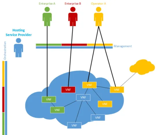
The type of services supported on VNPaaS can range from a simple firewall service for a single enterprise to a whole business communication suite based on IMS network for a 3rd party. A service may either be orchestrated out of existing services (VNF Forwarding Graph), deployed as new elements, or implemented as a combination of both. Figure 11 depicts an example of sharing network resources.
Figure 11: Example of 3 party enterprises sharing a Service Provider's infrastructure
There are 4 entities represented in the setup. The hosting service provider owns the infrastructure and resells shares of the infrastructure resources to 3rd parties. Enterprise A uses two VNF instances one of which is connected to a VNF instance in the hosting service provider's network. Enterprise B deployed a standalone VNF instance which is not connected to a VNF instance in the hosting service provider's network but might have connectivity to the enterprise corporate network. Operator A uses 3 VNF instances connected to one of the hosting Service Provider's VNF instances and also having connectivity to Operator A's home network.
The figure does not show how each of the VNF instances have been deployed but indicates that the Orchestration interface provides a part specific to each entity and having the hosting service provider sitting in between to apply policies for each entity.
7.3 Virtualisation
Target
All network functions which may be shared with a 3rd party are possible virtualisation targets. The assumption here is that by using virtual network functions, a certain level of separation of workloads is implied (see problems/issues). The Service Provider will define the toolkit of capabilities that it makes available as a platform. This toolkit may include the ability to instantiate and configure selected VNFs and develop other applications on virtual machines within the NFVI. The Enterprise may need tools to support the development of virtual networks based on VNFs in this environment.
7.4
Coexistence of Virtualised and Non-Virtualised Network
Functions
Operators already today share infrastructure resources when providing services to multiple users. Functions shared within this concept may remain non-Virtualised. The communication with virtual network functions shall be based on standardized interfaces.
7.5 Problem
description/Issues
To share infrastructure resources with 3rd parties, three main requirements need to be fulfilled: 1) Access control to API calls should be based on an authorized user identity.
2) Infrastructure resources need to provide mechanisms to separate workloads from different Operators.
3) Infrastructure resources and network functions need to provide an interface to monitor, guarantee and limit the usage of the resource by each Operator.
Additionally, management interfaces of services may be exposed to a 3rd party transparent to the VNPaaS Provider e.g. management of email server. This requires a management "pass-through" mode and a sophisticated isolation of the service so that it is not possible to break out the management domain of this particular service.
A VNPaaS would require usage of accounting etc. for the service.
A VNPaaS would require tools to support the creation of virtual networks using VNFs.
8
Use Case #4: VNF Forwarding Graphs
8.1 Motivation
A Network Function (NF) Forwarding Graph [1] defines the sequence of NFs that packets traverse. A simple Network Service [1] can be implemented in an NFV environment using point to point links. This use case demonstrates that more complex structures might be necessary as VNF Forwarding Graph (VNF FG) [1].
VNF FGs are the analogue of connecting existing Physical Appliances via cables as described in the NFV white paper. Cables are bidirectional and so are most data networking technologies that will be used in Virtualised deployments in the near term (e.g. Ethernet). In other words, a VNF Forwarding Graph provides the logical connectivity between virtual appliances (i.e. VNFs).
To realize the goals of NFV, Service Providers need to develop Network Services at an abstract level and then deploy them in instantiations bound to particular NFVI resources (compute nodes, infrastructure networking termination points, existing physical NEs, etc.) These abstract definitions of Network Services are a subject for further study, however, an abstract Network Service based on VNFs seems likely to include identification of the types of VNFs involved, the relationships between these VNFs and the interconnection (forwarding) topology along with related management and dependency relationships. Of course, a VNF FG can also interconnect with Physical Network Functions to provide a Network Service.
VNF FGs solve the following problems and/or provide benefits as compared with a physical appliance based forwarding graphs.
Table 1: Comparison of Physical Appliance Forwarding Graph and VNF Forwarding Graph
Attribute Physical Appliance Forwarding Graph VNF Forwarding Graph Efficiency Dedicated function and network capacity
sized for peak load
Function and network capacity sized to current load and shareable across functions
Resiliency Backups use specific hardware and dedicated network capacity
In some cases, backup functions can share hardware resources and network capacity in the NFV Infrastructure
Flexibility Lengthy deployment intervals for upgrades or new features when functions are hardware based
Shorter deployment intervals for upgrades and new features since functions are software based Complexity Additional configuration, physical interfaces
and/or support systems needed to make client-server IP/Ethernet switching implement middlebox forwarding graphs
Virtualised switching functions and/or configuration of VNFs can implement forwarding graphs in a more straightforward and efficient manner
Deployability Deployment in another Operator's or
Enterprise's network requires physical boxes, interfaces and configuration to connect to end users
Virtualised functions and switching more easily deployable in Operator's or Enterprise's network. Virtualisation of networking functions can reduce configuration complexity
8.2 Description
The VNFs in a VNF FG have standardized and/or published interfaces (e.g. L1, L2, L3, L4 and/or L7). In some VNF FGs, packets have a specific destination (e.g. a (set of) (virtual) server functions) while in others; packets have no specific destination (e.g. the Internet). Many other use cases share characteristics with this VNF FG use case and requirements, architecture and specifications on these common characteristics should meet the NFV goals for enabling migration from existing physical network functions to virtual analogues as well enabling implementation of new functions and arrangements not previously envisioned.
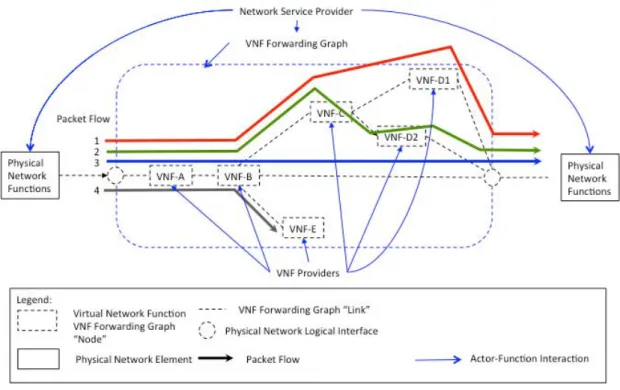
Actors and roles: see [1] for description of Network Service Provider. A VNF Provider is a vendor implementing the software for a VNF and NFV management and orchestration is the set of operational systems supporting the NFVI. The VNF forwarding graph use case has the following logical parts and actor-entity relationships as illustrated in the example of Figure 12. See [1] for definitions of common NFV terminology as well as the following definitions:
Physical Network Function: An implementation that is part of an overall service that is not virtualised which is
deployed, managed and operated by a Network Service Provider. This could be a physical access or backbone network, standalone VM not part of a VNF FG, an interconnect point between multiple VNF FGs provisioned by different administrator domains (e.g. NSPs).
Physical Network Logical Interface: The boundary between a VNF FG and Physical Network Functions is specified
by the Network Service Provider. It may be based upon fields in a packet header that are the source or destination of packets entering or exiting a VNF across an interface from/to a Physical Network Function. For example, a VLAN on an Ethernet port that connects a physical port (e.g. on a NIC or a switch) in the NFVI to a physical/logical port on a Physical Network Function.
Packet Flow: The net outcome that contributes to the overall service is that certain groups of packets follow the same
path through the VNF FG. Note that the VNF functionality, configuration and state determine the packet flow through the VNF forwarding graph and the VNFs traversed may differ in each direction for packets of the same bi-directional flow.
NFV Network Infrastructure: provides connectivity services between the VNFs that implement the forwarding graph
links between VNF nodes in hardware and/or software as shown by the red arrows as controlled by NFV management and orchestration. It may contain functions including traffic classification, tunnel encapsulation/decapsulation, traffic steering and/or some forms of load balancing.
Figure 12 provides an example of a VNF Forwarding graph that a Service Provider may use as part of its service design. In this example, the Service Provider has designed an end-end network service between two physical network functions that involves several VNFs (VNF-A, VNF-B, VNF-D1, VNF-D2, VNF-E). These VNFs have been provided by one or more VNF providers. These VNFs have some metadata associated with them which describe the essential
characteristics of the VNF. The actual Network Service is the set of all possible packet flows that traverse the VNF FG and any PNFs, for example, as illustrated in Figure 12. A Network Service involves information (as well as logic in the VNFs themselves) that make use of the VNF FG.
Figure 12: Logical View of Virtual Network Function Forwarding Graph (VNF FG)
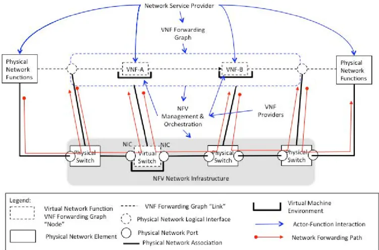
The logical VNF FG use case is mapped to physical elements and additional actor-entity relationships as illustrated in the example of Figure 13 that uses additional terminology not defined in [1] as follows:
Physical Network Association: An association relationship between the NFV Network Infrastructure and a Physical Network Port on a Physical Network Function known by management and orchestration at the boundaries between
VNFs and physical elements. This may be the legacy interconnect interface between the NFV Infrastructure (NFVI) network and the (physical) existing network.
Physical Network Port: A physical port on a physical network function or a physical network switch/router or a
physical NIC.
Network Forwarding Path: The sequence of hardware/software switching ports and operations in the NFV network
infrastructure as configured by management and orchestration that implements a logical VNF forwarding graph "link" connecting VNF "node" logical interfaces (e.g. a VNIC on a VM). The VNF FG information describes characteristics of these "links." Traditional methods to implement network forwarding graphs include: physical interface based
forwarding between physical appliances, VLAN-based bridging domains, IP subnets, tunnel configurations, policy based routing, and specific BGP configurations. SDN controlled switching (e.g. OpenFlow) can implement these traditional methods, but can also directly create network forwarding graphs in different, dynamic and/or unique ways.
Virtual Machine Environment: The characteristics of the compute, storage and networking environment for a specific
(set of) VNF software elements as configured by management and orchestration. This is determined by information supplied by a VNF provider and information supplied by the Network Service Provider for the VNF FG.
The Service Provider needs to be able to instantiate all of these VNFs in their NFVI. The Service Provider needs to be able to predict the range of the expected behaviour and performance of the end-end network service and understand the effects of various options for binding the abstract Network Functions that comprise the service description to the physical infrastructure. Figure 13 illustrates an end-end network service comprised of VNFs between two physical network functions where the traffic is forwarded through two physical devices and two VNFs (VNF-A, VNF-B). In this example, VNF-A is a completely Virtualised network function since the network connectivity is also virtualised by a virtual switch, but VNF-B is only partially Virtualised with data plane traffic passing through a physical switch rather than a virtual switch implemented on an NFVI compute domain node.
Figure 13: Physical View of Virtual Network Function Forwarding Graph (VNF FG)
A particular type of VNF FG a (e.g. the preceding examples) where the nodes and links have a similar topology with parameter definable attributes (e.g. capacity, performance constraints) should make use of a common template. Provisioning a VNF graph means that a specific instance of a VNF FG according to this template needs to be
instantiated by the NFV framework for a set of flows (e.g. consumers, enterprises, wireless users accessing a Gi LAN, etc.) typically covering a geographic area.
When a Network Service is provisioned, the NFV Framework needs to keep a record of the Infrastructure resources that are used so that future operational processes (such as localization of a fault, restoration, resizing or termination of the service) can be undertaken on all relevant objects in the VNF FG.
Provisioning, restoration and resizing occur on an instance by instance basis.
An example of a VNF FG commonly encountered is where packets traverse a VNF implementation of a router, an intrusion detection device, a firewall NAT, and a load balancer that distributes traffic to a pool of servers. One deployment example is a subscriber-oriented service for wireless users deployed at a NFVI-PoP on a wireless Gi LAN or in a wireline network.
8.3 Virtualisation
Target
The virtualisation target requires the following capabilities in support of a VNF FG:
1) An information model that enables a Network Service Provider to describe to management and Orchestration entities the characteristics of nodes and links of a VNF FG in terms of capacity, performance, resiliency, constraints, security, required virtual compute/networking environment requirements and other parameters. 2) An information model supplied by the VNF Provider that describes the NFVI resources needed to map an
individual VNF instance (e.g. image running on a VM) to NFVI resources (e.g. virtual compute, storage and networking).
3) The Network Service Provider needs to be able to specify a mapping from the VNF FG that determines the selection and configuration of physical and/or virtual switching elements in the NFVI that are controlled via traditional and/or SDN methods.
4) An information model that allows a Network Service Provider to specify logical and physical interconnect points between the NFVI and Physical network functions, which may be interconnect points to other
administrative domains (e.g. another operator) or VNF FG s, such that these can be implemented and managed by NFV management and orchestration. L1, L2 and/or L3 physical and/or virtualised L2/L3 networking environments.
5) The Network Service Provider needs to be able to identify the VNF FGs that are mapped to NFVI resources (e.g. compute domain nodes, hypervisor domain resources, infrastructure networking resources including physical links and physical network elements).
8.4
Coexistence of Virtualised and Non-Virtualised Network
Functions
Coexistence, interoperation, migration, and interaction between physical/virtual network functions is applicable to this use case in the following areas:
• Interfaces provided by NFVI between a VNF Forwarding Graph and a physical network function or a physical network switch as configured and managed by NFV management and orchestration.
• Interfaces between, configuration and control plane interoperability between a physical switch and a virtual switch as provided by NFVI and managed by NFV management and orchestration.
• EMS, OSS, and/or BSS interfaces to physical/virtual function control and management augmented by any additional information exchange methods needed by NFV management and orchestration.
• Support by NFVI and NFV management and orchestration for migration from a physical network function to a virtual network function (or vice versa).
• Support by NFVI and NFV management and orchestration for interaction for control/management plane interoperability for physical network logical associations and physical ports (e.g. VLANs, tunnel, SDN configurations).
8.5 Problem
description/Issues
The challenges of the VNF Forwarding Graph (VNF FG) use case are driven primarily by the information model and its usage in achieving the virtualisation target as previously described. In this context, the following are specific
challenges:
• Specifying attributes of a VNF FG as supplied by a Network Service Provider such that the required overall performance, capacity, and resiliency is achieved. Measurement methods to validate that these are achieved may be needed.
• Specifying attributes supplied by a VNF provider such that each VNF's contribution to the overall performance, capacity and resiliency of the VNF FG is achieved. Measurement, testing, and/or validation methods to validate that these are achieved may be needed.
• VNF FG interconnection selection by the Network Service Provider from a broad set of networking
alternatives such that acceptable efficiency results and that the requirement networking capacity, performance and resiliency is achieved.
• Network Service Providers need to support end-end services that cross administrative boundaries, hence aspects involving multiple administrative domains in terms of operation, interworking, and migration to/from physical network function implementations need to be further described.
• The abstract end-end network service will require further definition of additional relationships between the VNFs that comprise the service. The definition of the service and the identification of the categories of relationships needs further study to facilitate service creation using VNFs by cooperating Network Service Providers.
Resources need to be assigned to implement the "nodes" and "links" of a VNF FG initially in response to an operator provisioning request. The assignment of resources that implement "nodes" and "links. May need to be modified in response to load changes and/or a catastrophic failure in the event that other mechanisms do not adjust capacity or restore the forwarding graph resources.
9
Use Case #5: Virtualisation of Mobile Core Network
and IMS
9.1 Motivation
Mobile networks are populated with a large variety of proprietary hardware appliances. Network Functions Virtualisation aims at reducing the network complexity and related operational issues by leveraging standard IT virtualisation technologies to consolidate different types of network equipment onto industry standard high volume servers, switches and storage, located in NFVI-PoPs-Such consolidation of hardware is expected to reduce Total Cost of Ownership (TCO). Flexible allocation of Network Functions on such hardware resource pool could highly improve network usage efficiency in day-to-day network operation. This also helps to accommodate increased demand for particular services (e.g. voice) without fully relying on the call restriction control mechanisms in a large-scale natural disaster scenario such as the Great East Japan Earthquake, during which mobile networks faced a massive number of call attempts for voice communication because most people urgently tried to confirm the safety of their family, friends, etc. Possible advantages of the virtualisation of mobile core network and IMS include the following:
• Reduced TCO.
• Improved network usage efficiency due to flexible allocation of different Network Functions on such hardware resource pool.
• Higher service availability and resiliency provided to end users/customers by dynamic network reconfiguration inherent to virtualisation technology.
• Elasticity: Capacity dedicated to each Network function can be dynamically modified according to actual load on the network, thus increasing scalability.
• Topology reconfiguration: Network topology can be dynamically reconfigured to optimize performances. In addition, Network Function Virtualisation enables the creation of a competitive environment where innovative implementations of 3rd party network applications can be supplied by unlocking the proprietary boundaries of current Mobile Core and IMS implementations.
9.2 Description
The 3GPP™ is the standards developing organization that defines the Network Architecture and specifications for the Network Functions (NFs) for mobile and converged networks.
In the Evolved Packet Core (EPC), which is the latest core network architecture for a cellular system, examples of Network Functions include MME, S/P-GW, etc.