System Engineering Guidelines
IEC 62591
Wireless
HART
®
PREFACE
Emerson Process Management has developed the “System Engineering Guidelines” for
WirelessHART to support the requirements of WirelessHART end users adopting self-organizing mesh networks within the process industry. This document is intended to provide complete technical guidance for using WirelessHART devices and applications.
Vital information is captured in the document for the user to make full use of the system application. The information is presented in a ‘generic’ fashion and does not incorporate any ‘value added’ features available from any specific vendor.
This document is divided into two Parts for better understanding of the engineering guidelines. The PART I addresses the application of WirelessHART technology in different project execution stages starting from the appraise (conceptual design) to the operation phase.
PART II explains the various terminologies of WirelessHART, that are used during the various stages of project execution.
The guidelines documented herein include a description of the system functions and capabilities, contingencies and alternate modes of operation, and step-by-step procedures for system access and use. This document assumes the reader is proficient with HART instrumentation; and therefore it focuses on the unique aspects of deploying WirelessHART systems. Unless stated otherwise, the reader should assume the project steps are the same for HART and WirelessHART instrumentation.
This technical guidelines document summarizes the essential pre-requisites and general guidelines necessary for smooth execution of the project that contains WirelessHART Technology. The guidelines provided herein are applicable for small and large scale projects. The technical guidelines may only be used and operated-on by qualified personnel capable of observing the safety instructions from device manuals. This document is for informational purpose and is provided on an “as is” basis only. The document may be subject to future revisions without notice. The authors and contributors will not be responsible for any loss or damage arising out of or resulting from a defect, error or omission in this document or from any personnel’s use or reliance on this document.
We want to hear from you
Your comments and suggestions will help us to improve the quality of system engineering guidelines. If you have any suggestions for improvements, comments, recommendations or a query, please feel free to drop your feedback to a Wireless Specialist:
Definitions and Acronyms
The following definitions are used within this document.
Ancillary device
Any device that does not contain measuring sensor or output to the process for actuation.
Gateway
Enables communication between wireless field devices and host applications connected to an Ethernet, Serial, or other existing plant communications network; management of the wireless field network; and management of network security. Conceptually, the gateway is the wireless version of marshalling panels and junction boxes. The gateway functionality may also exist in native WirelessHART I/O cards with field radios.
Host System
Any system accepting data produced by the WirelessHART Field Network (WFN). This could be a DCS, PLC, RTU, Data Historian, asset management software, etc.
Join Key
A 128 bit security key used to authenticate wireless field devices when joining the network, including encryption of the join request.
A common Join Key may be used among all devices on a given network, or each device may have a unique join key.
Note: When displayed in hexadecimal format via a browser or handheld, this results in a 32 character hexadecimal field.
Network ID
Each gateway at a facility or location should be programmed with a unique Network ID. All authenticated wireless field devices with the same Network ID will communicate on the same network and gateway.
Update Rate
The user specified interval at which a wireless field device will detect a measurement and transmit the measurement to the gateway (i.e. sample rate). The update rate has the largest impact on battery life due to the powering of the device sensor. Update rate is independent of radio transmissions required for mesh peer-to-peer communication, “hopping” via multiple devices to transmit a measurement back to the gateway, and downstream communications from the host system to the wireless field device.
Wireless Adapter
Enables an existing 4-20 mA, HART-enabled field device to become wireless. Adapters allow the existing 4-20 mA signal to operate simultaneously with the digital wireless signal.
Wireless Field Devices
Field device enabled with a WirelessHART radio and software or an existing installed HART-enabled field device with an attached WirelessHART adapter.
Wireless Field Network
A self-organized network of wireless field devices that automatically mitigate physical and RF obstacles in the process environment to provide necessary bandwidth for communicating process and device information in a secure and reliable way.
Wireless Repeater
Any wireless field device used to strengthen a wireless field network (by adding additional communication paths) or expand the total area covered by a given mesh network.
Acronyms
The following acronyms are used within this document.
Abbreviation Description
AMS Asset Management System CSSP Control Systems Security Program DCS Distributed Control System DD Device Descriptor
DSSS Direct-Sequence Spread Spectrum FAT Factory Acceptance Test
FEED Front End Engineering and Design
HART Highway Addressable Remote Transducer HMI Human Machine Interface
LOS Line of Sight
NFPA National Fire ProtectionAssociation PFD Process Flow Diagram
P& ID Piping and Instrument Design PLC Programmable Logic Controller
RF Radio Frequency
RSSI Received Signal Strength Indicator SIT Site Integration Test
SPI Serial Peripheral Interface SPL Smart Plant Layout
TSMP Time Synchronized Mesh Protocol TSSI Temporal Single-System Interpretation UDF User Defined Fields
Contents
PART I WirelessHART Project Execution
... 11
1
Introduction ... 12
1.1 Purpose ... 12
1.2 Scope ... 12
1.3 WirelessHART in Project Execution Lifecycle ... 12
2
Project Concepts ... 14
2.1 Traditional Approach ... 14
2.2 Technology Assesment ... 14
3
Appraise ... 17
3.1 Application ... 17
3.2 Technology ... 18
3.3 Operations ... 18
3.4 Maintenance ... 18
3.5 Appraise Phase Documentation ... 19
4
Pre-FEED ... 20
4.1 Cost Benefit Study ... 21
4.2 Preliminary Design Basis ... 23
4.3 Project References ... 24
4.4 Pre-FEED Documentation and Tools ... 24
5
Front End Engineering Design (FEED) ... 25
5.1 Scope Definition of Engineering Execution ... 26
5.2 Environmental Considerations ... 27
5.3 WirelessHART Functional Design Requirements ... 27
5.4 WirelessHART Infrastructure Requirements ... 27
5.5 Operational Requirements ... 28
5.6 Design Inputs Documents Review ... 28
5.7 Development of Basis for Design ... 28
5.8 Initial Design Review ... 30
6
Execute ... 31
6.1 WirelessHART Field Network – Design Engineering Overview ... 32
6.2 Design Resources ... 33
6.3 Wireless Device Selection based on process measurement ... 33
6.4 Design Criteria Development ... 35
6.5 Identify Candidate Measurement Points ... 35
6.6 Database Field for Wireless Network Assignment ... 36
6.8 Scoping ... 38
6.9 Detailed Design Specifications ... 42
6.10 Spare Capacity and Expansion ... 49
6.11 Fortifying ... 49
6.12 WirelessHART Availability and Redundancy... 51
6.13 WirelessHART Security ... 51
6.14 Alarm Handling with WirelessHARTDevices ... 51
6.15 Datasheet Parameters for WirelessHART Transmitter ... 54
6.16 Tools and Documentation ... 55
6.17 Testing ... 55
6.18 Factory Acceptance Test (FAT) ... 56
6.19 Site Installation ... 59
6.20 Site Installation Plan ... 60
6.21 Network Installations ... 60
6.22 Wireless Connection Test Procedure ... 61
6.23 Network Checkout Procedure ... 62
6.24 Lightning Protection ... 62
6.25 Device Parameter Configuration Verification ... 63
6.26 Loop Checkout/Site Integration Tests ... 64
6.27 Bench Simulation Testing ... 64
6.28 Provision of Spares ... 64
6.29 Removal of Redundant Equipment ... 64
6.30 Pre-Commissioning ... 64
6.31 Site Acceptance Test (SAT) ... 65
6.32 Commissioning and Start-up ... 66
7
Operate ... 68
7.1 Asset Monitoring ... 68
7.2 Alarm and Alerts Philosophy ... 69
7.3 Data Management Concepts... 69
7.4 Maintenance Practices ... 69
8
Project Management ... 70
8.1 WirelessHART Project Management Overview ... 70
8.2 Work Breakdown Structure and Cost Estimation ... 70
8.3 Subcontractor Scope Management ... 70
8.4 Project Scheduling ... 71
8.5 Responsibility and Skills Matrix ... 71
8.6 Managing Project Change Requests ... 71
8.7 Progress Reviews and Reporting ... 72
8.8 Customer Deliverables ... 72
8.9 Training ... 72
8.10 WirelessHART Procurement and Contract Plan ... 72
8.11 Material Requisitions ... 72
PART II WirelessHART Field Network Components
... 74
9
Field Device Requirements... 75
9.1 Support for WirelessHART Functionality ... 75
9.2 Device Mounting ... 76
9.3 Field Device Power ... 76
9.4 Field Device Security... 78
9.5 Approvals ... 79
9.6 Accessibility ... 79
9.7 Manufacturer Documentation ... 80
10
Ancillary
Wireless
HART Devices ... 81
10.1 Gateways ... 81
10.2 Wireless Repeaters ... 82
10.3 WirelessHART Adapters ... 82
10.4 WirelessHART Handheld Communicator ... 83
11
Measurements and Choosing
Wireless
HART Device ... 84
11.1 Use of WirelessHART for Multivariable Process Measurements ... 84
11.2 Use of WirelessHART in Various Process Applications ... 85
12
Host System Requirements ... 86
12.1 Use of Standard Protocols ... 86
12.2 Wireless Host System ... 86
12.3 Host Integration ... 88
12.4 Interoperability ... 89
12.5 Host System Support for WirelessHART Functionality ... 89
12.6 Device Descriptions Files (DD) ... 90
12.7 Configuration Tools ... 90
12.8 Control System Graphics ... 90
12.9 Node Addressing and Naming Conventions ... 91
12.10 Alarms and Alerts ... 91
12.11 Maintenance Station and Asset Monitoring ... 91
12.12 Historian ... 91
13
Documenting in Intergraph SPI 2009 ... 92
13.1 User Defined Fields ... 92
13.2 Filtered Views ... 93
13.3 Creating Instrument Types ... 94
13.4 Loop Drawings ... 98
13.5 Drawings in SPL – Smart Plant Layout ... 101
13.6 Documenting Security Information ... 102
Appendix B.
Wireless
HART vs. HART Comparison ... 104
Appendix C.
Design Resources ... 105
Appendix D.
Wireless Spectrum Governance ... 106
Appendix E.
References ... 110
PART
I
1
Introduction
WirelessHART is a global IEC-approved standard (IEC 62591) that specifies an interoperable self-organizing mesh technology in which field devices form wireless networks that dynamically mitigate obstacles in the process environment. This architecture creates a cost-effective automation alternative that does not require wiring and other supporting infrastructure.
WirelessHART field networks (WFN) communicate data back to host systems securely and reliabily and can be applied to both control and monitoring applications.
The similarities between WirelessHART and HART allow wireless devices to leverage the training of existing process organizations, minimizing change and extending the benefits of automation to end users who previously could not justify the costs associated with typical wired capital projects. This opportunity and long-term benefit justifies the addition of new end users including maintenance, safety, environmental, and reliability, in FEED (Front-End Engineering and Design) of new projects. Additionally, by removing the physical constraints of wiring and power (as well as reduced weight and space). Wireless networks provide new flexibility in project execution providing solutions which can mitigate risk and improving project schedules.
1.1
Purpose
The purpose of this IEC 62591 WirelessHART System Engineering Guidelines is to demonstrate the applicability of WirelessHART devices in Projects of any size.
1.2
Scope
This document includes considerations for WirelessHART Technology and devices through the complete project cycle as well as subsequently during plant operations.
Differences are highlighted between HART and WirelessHART specifications & WirelessHART device types that are unique to the WirelessHART standard (IEC 62591).
1.3
Wireless
HART in Project Execution Lifecycle
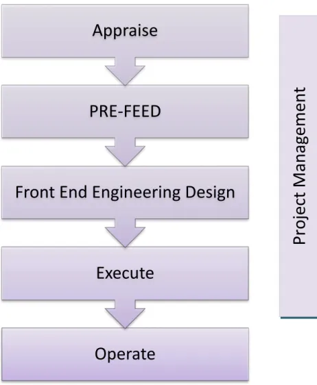
Figure 1 illustrates a typical framework for project execution and will be used as a basis for describing application of WirelessHART by each phase of the project . Although WirelessHART can be introduced at any phase of a project a strategic benefit is realised by its introduction during the early part of the project execution cycle.
Figure 1: WirelessHART in Project Execution Lifecycle
Operate
Execute
Front End Engineering Design
PRE-FEED
Appraise
Pro
je
ct
M
an
ag
eme
2
Project Concepts
This topic explains the benefit of today’s technology over traditional project architectures. WirelessHART technology integrated in a conventional project can be used as risk reduction tool during execution whilst providing greater flexibility and a significant benefit to the plant asset during its life cycle.
2.1
Traditional Approach
Traditional methods of wired control networks make use of conventional communications like 4-20 mA, HART, Foundation Fieldbus, Profibus and other bussed solutions. Significant efforts are essential in the pre-FEED and FEED phases for planning long run cables whilst managing spares considerations associated with the infrastructure in the anticipation of any potential change which may occur on the project.This is an established process with limited scope for innovation to radically change the way design engineers and project managers approach a project.
In addition, measurement of parameters in locations inaccessible to cable trays and therefore wired connection, are always an area of concern and sometimes such measurements are eliminated from the design process as being to costly to implement during the CAPEX phase of a project.
Spare considerations during the initial execution phase, if incorrect, can cause a major impact due to modifications at a later stage. In a typical project environment, frequent changes in I/O database, addition/deletion or reallocation of instruments, change in instrument types, delayed or late changes in package vendor data etc negatively impact project time and cost. During the maintenance phase, if instruments and therefore I/O points need to be added/changed/moved, then lengthy procedures need to be followed for wired signals such as HSE, work permits, correct isolation procedures, and requisite cabling to connect the field instrument to the control system. These activities require coordination between multiple plant departments. Furthermore, routine inspection to ensure that the cable and associated infrastructure continue to operate trouble free, can be costly and time consuming and divert valuable resources away from operating the plant.
2.2
Technology Assesment
Today’s WirelessHART technology provides an opportunity to execute and build a more efficient plant compared to the traditional approach.
The Project technical authority will make a decision to use wireless based on the following criteria:
• Economic Assessment
• Potential operational savings
• Potential benefit of new measurements providing additional process insight
• Benefits of adding measurement not previously considered feasible for inclusion in the automation system due to economics or practicality – example: monitored safety showers
• Benefits of flexibility in project execution – example: ease of moving or adding I/O points during construction to cost effectively manage onsite changes
The economics of installing field wiring has primarily limited the benefits of automation to process control and safety applications with additional points added over the life of the plant to resolve critical problems. Since WirelessHART does not require wires for communication or power, the financial impediment in determining whether point is automated or not is redefined.
Special consideration should be given to understand the automation needs of new process plants to ensure they meet stricter safety, environmental, reliability and performance criteria. Below are a few examples:
• Many new plants are designed to operate with fewer personnel. Upgrading simple gauges to wireless field devices can automate the manual collection of data from the field in order to increase worker productivity and reduce exposure to hazardous environments.
• Many existing facilities have been modified in order to meet emerging environmental regulation. Real time monitoring of volatile organic compound release (VOC) from pressure safety valves and the conductivity and temperature of effluent waters can ensure environmental compliance.
• Remote monitoring of safety showers and gas detectors during construction and operation can provide new levels of safety response.
• New environmental regulation often requires redundant monitoring systems on assets like tanks that were not required in the past. WirelessHART can provide a cost effective, reliable secondary communication method and monitoring method.
• Monitoring of steam traps and heat exchangers can provide real time information for minimizing plant energy consumption.
Cost effective field information accessible via WirelessHART field devices enables non-traditional end users of automation to be considered in the FEED and Design phases. A designer should be aware of initiatives for safety, environmental protection, energy consumption, and reliability in addition to the traditional considerations for process automation. WirelessHART provides a unified infrastructure for extending the benefits of automation to multiple plant initiatives without the need for multiple forms of I/O infrastructure.
Mitigation strategies of traditional risk models’ lack innovation. WirelessHART provides greater flexibility and an advantage of minimum engineering efforts, in addition to greater savings in cost and time during any project phase, as compared to the traditional approach.
The project should establish design rules to define which measurement and control points are suitable for WirelessHART in order to enable consistent and efficient engineering for subsequent project phases.
3
Appraise
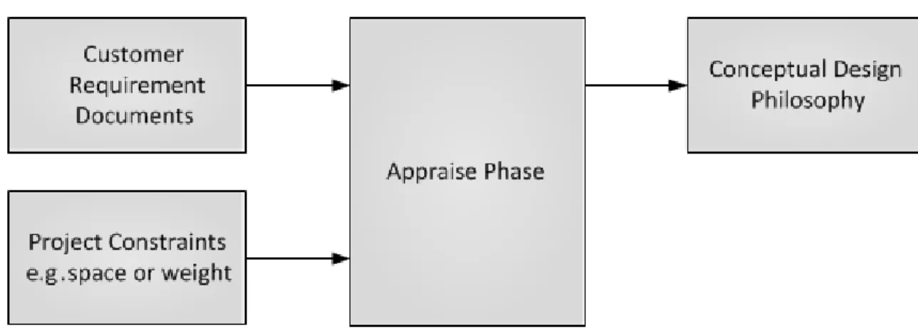
Appraise phase (conceptual design) requires high level customer requirements or project constraints as input. In this phase a simple statement of requirements with identified constraints or objective will suffice. Selection of Wireless technology in this phase allows a simple generic philosophy statement to be made on how the architecture can be utilised to meet the needs of both the business and the project.
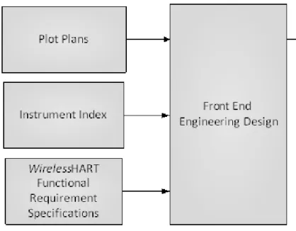
Following Figure 2shows the inputs and outputs of the Appraise phase...
Figure 2: Conceptual Design Phase
During the Appraise phase it is likely that a summary of the technology and its application will be required by the project stakeholders in order for them to formulate a practical view of applicability to the project. Additionally, typically plant personnel engaged in the early phase of the project such as Operations and Maintenance should also be part of this appraisal.
3.1
Application
WirelessHART can be applied to a wide variety of process applications in all process industries spread over differing geographical terrain. Evaluate following factors for the WirelessHART applications.
• Process monitoring and measurements which are at remote place and uneconomical to consider for monitoring
• Equipment Health Monitoring
• Environmental monitoring, energy management, regulatory compliance
• Extreme environmental conditions for wired installations (hot, wet and corrosive)
• Roatating Equipments
• Asset management, dianostics and predictive maintenance
• Simple Closed-loop control (when appropriate)
• API Seal Flush Plans
• Secondary Systems
3.2
Technology
WirelessHART technology can be deployed by evaluating the following factors...
• Minimizing the cost
• Ease of installation
• Reduced time for Installation and Commissioning
• Ease of Maintenance
• Ease of expansion for future I/O point (Scalability)
3.3
Operations
WirelessHART field network benefits Operators, shift supervisors, Production / Field Management, and facilities or engineers to collaborate to optimize process operations by collecting data in organized manner, including remote locations, to ensure that the delivery of right information to plant operations team assists them to make the right decisions to improve the plant throughput. WirelessHART operations benefits are...
• Covering monitoring points which are normally inaccessible to plant operator
• Increasing safety by minimizing plant operators rounds at hazardous locations and
• Better Alarm handling and reporting
• Transmitters provide better insight than gauges and switches through trending
3.4
Maintenance
There are no special maintenance requirements for the WirelessHART devices apart from changing the batteries.
WirlessHART devices provide greater advantage for maintenance in hazardous areas. The batteries are Intrinsically Safe and power-limited, so that they can be changed with the device in situ without risk of causing a source of ignition.
The diagnostic information provided to the Asset Management System, alerts the technician on
3.5
Appraise Phase Documentation
3.5.1
Reference documents
Customer Requirement Specification (Customer Statement of requirements)
3.5.2
Deliverables
Conceptual Design Philosophy/Architecture Economic Analysis of technology and solutions Project imperatives
4
Pre-FEED
In Pre-FEED, the requirements, philosophies and imperatives established in Appraise phase are further elaborated. Deployment of WirelessHART for identified application can be explored and verified in further detail during this phase.
Following Figure 3 shows the inputs and outputs of the Pre-FEED phase.
Figure 3: Pre-FEED Phase
An integrated approach should be used for incorporating wireless into a project. Wireless should be merged with the established procedures for a wired project. The key consideration is to use the right field device technology for the right application and expand consideration for possibly new end user communities during the FEED process.
WirelessHART for Control and Monitoring Applications
WirelessHART is designed for both control and monitoring applications. Most current use cases emphasize monitoring applications due to conservative adoption of technology to meet the needs of a conservative industry. The use of wireless control applications is continuing to evolve with the introduction of discrete output devices for performing simple control functions. The Table 4-1: Selecting the Right Protocol below provides a high level summary for selection of the right protocol when factoring in loop criticality; cost to engineer and implement; and location of field devices relative main process areas and host systems.
Safety Systems Critical Control ON –OFF Control In- Plant Monitoring Remote Monitoring
Conventional
Fieldbus
WirelessHART
Legends Based on Technical and/or Cost considerations
Most appropriate solution
Appropriate in some cases
Least effective Solution
Table 4-1: Selecting the Right Protocol
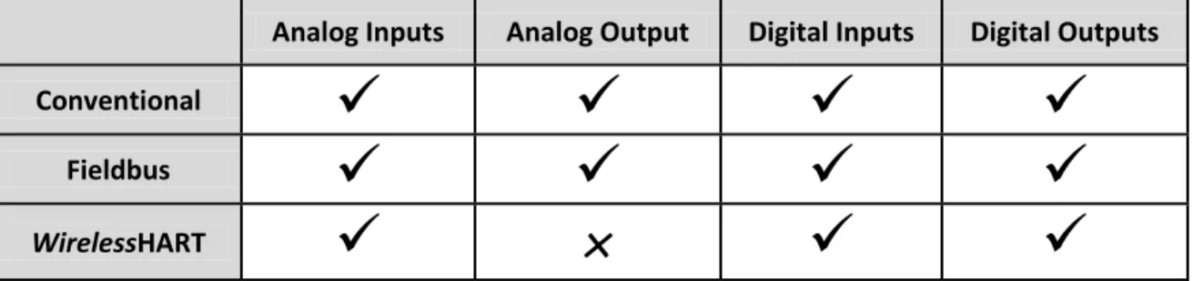
The following Table 4-2: Selecting signal types with Right Protocol shows the available technology solution for different signal types.
Analog Inputs Analog Output Digital Inputs Digital Outputs
Conventional
Fieldbus
WirelessHART
×
Table 4-2: Selecting signal types with Right Protocol
4.1
Cost Benefit Study
WirelessHART and wired solutions need to be evaluated during Pre-FEED phase, for comparison from a cost and time perspective. Furthermore assessments on the benefits to schedule improvement (by phase) and change amangement should be an input to this cost benefit study.
Following factors can be considered for this comparison :
• Main Junction Box requirements
• Secondary Junction Box requirements
• Main Cable Tray requirements
• Secondary Cable Tray requirements
• Multi-core Cable requirements
• Power supply in system cabinets
• System Cabinet requirements
• Marshalling Cabinets
• 3D modelling review for Cable tray routing, Cable tray Engineering & Location of junction Box
• Cost of change request management
• Time and efforts for installing cable trays and cables
• Power consumption requirement
• Space requirements
• Material Weight Reduction
• System design time requirements
• Material consideration based on area classification and protection concept
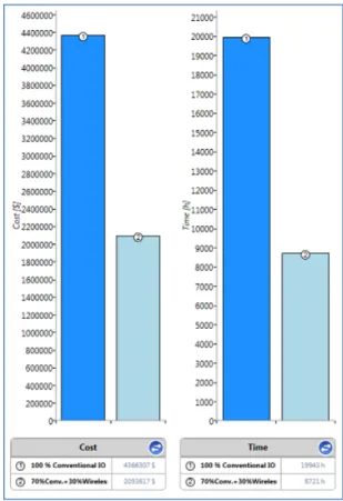
In addition to the above criteria, accommodating changes is cheaper and efficient with
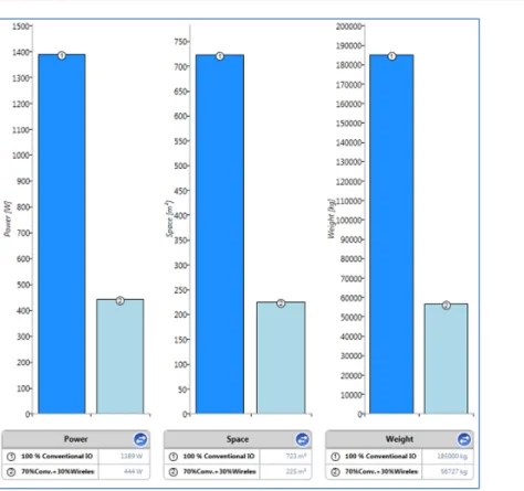
WirelessHART during any project phase. Typical case studies for cost, time, power, space and weight savings are shown in Figure 4 and Figure 5. These case studies should usually consider the criteria listed above.
Figure 5: Case study for Power, Weight and Space savings
4.2
Preliminary Design Basis
The updated Customer Requirement Specification along with the preliminary project documents available like site plan/layout, P&IDs, Instrument index etc can be utilized to determine preliminary design basis. This includes the quantity of WirelessHART instruments, gateways and repeaters to create a pervasive sensing network. Assumptions on the basis of experience for similar plants/units, can be made in absence of requisite inputs.
Considering requirements of WirelessHART for indoor, outdoor and remote locations, the preliminary network topology for the Wireless Field Network can be worked out.
Suitable interface solution need to be considered for connection of the multiple Wireless Field Networks to the host system and AMS.
During the Pre-FEED phase, spectrum approvals for the end-user and any intermediary locations should be verified. Refer to Appendix D Wireless Spectrum Governance for more details.
4.3
Project References
Previous projects operating with WirelessHART, are a rich source of information and reference for new planned WirelessHART implementation. We can look towards these references as the first line of help to overcome specific issues encountered in new installations.
4.4
Pre-FEED Documentation and Tools
This section explains about documentation required in pre-FEED phase.
4.4.1
Reference documents
1. Initial Plot Plan
2. Initial 3D layout drawings 3. Initial P&ID
4. Instrument Index
5. Customer Specification Documents 6. Proposal Documents for cost estimates
4.4.2
Deliverables
1. Initial Wireless Field Network System Architecture 2. Measurement Signal Types
5
Front End Engineering Design (FEED)
Front End Engineering Design is an important stage where key deliverables exist for wireless, for example: cost estimation , design guidelines, and specifications.Collaborative efforts put in by all stakeholders during FEED, will help in capturing all project specific requirements and avoid significant changes during the Execution phase.
The following factors can be evaluated during the FEED phase for WirelessHART deployment in the project.
• Environmental Considerations
• WirelessHART Functional Design Requirements
• Scope Definition of Engineering Execution
• WirelessHART Infrastructure Requirements
• Operational Requirements
• Design Inputs Documents Review
• Development of Basis for Design
• Risk Assessment and Initial Design Philosophy Review Following Figure 6 shows the inputs and outputs of the FEED phase.
5.1
Scope Definition of Engineering Execution
Stakeholder meetings are important to ensure all disciplines understand the scope of Wireless applications, a review of the potential benefits in key areas of the work break down structure can be discussed so that appropriate training and strategy is put in place to realise potential benefits.. Project work dependencies must be clearly distributed within the project team so that any schedule efficiencies can be realised.
In-house wireless network requirements shall be discussed to define the scope of Integration of WFN and WPN network.
Wireless Communication network availability, redundancy, WirelessHART equipments supply, installation, configuration and commissioning site work activities, spare requirements scope must be clearly defined.
Overall Wireless Network architecture design, Wireless device location, minimum distance and coverage between access points, network coverage and performance requirement shall be considered in the scope statement. Supplementary wireless network devices such as
WirelessHART handheld communicator, Mobile worker supply scope shall be defined.
Determine the field device types and WirelessHART Signal types for project implementation. Following signal and device types shall be evaluated for WirelessHART implementation (refer to Emerson Literarture for the most up to date measurement types and innovations).
• Pressure
• Temperature
• Flow
• Level
• Tuning Fork Level
• Conductivity
• pH
• Corrosion
• Tank Gauging
• Guided Wave Radar
• Discrete Position Monitoring
• Discrete Inputs
• Discrete Outputs
• Acoustic (Steam Trap and PRV monitoring)
• Vibration
5.2
Environmental Considerations
Check for hazardous area classification requirements, temperature class; ambient temperature of plant.
Regional and country specifics RF frequency usage norms shall be considered.
5.3
Wireless
HART Functional Design Requirements
During initial stage of FEED, Customer’s functional requirements are translated into a network infrastructure, device charecteristics, host interfaces, and applications documented in the design specification as well as boundary conditions associated with WirelessHART applications.
5.3.1
Wireless
HART Requirement Specifications
Following points shall be considered for developing the WirelessHART design. 1. Network environment and Area Classification
2. WirelessHART System Architecture 3. Operational requirements
4. Data requirements 5. Interfaces
6. Testing
7. Spare consideration
8. Documentation requirements 9. Training
10. WirelessHART network Security, reliability and interoperability requirements.
5.4
WirelessHART Infrastructure Requirements
Carryout plot plan reviews and determine the infrastructure requirements for developing 1. System Architecture
2. Wireless Field Network (IEC62591 WirelessHART Field Instruments) design 3. Automation Host system interface
5. Asset Management System (Field Device and Field Network configuration and diagnostics
5.5
Operational Requirements
Following factors shall be considered for operational requirements Process Monitoring and signal types
1. Device Diagnostic requirements 2. Loop response time requirements 3. DCS HMI requirements
4. Redundancy requirement
5. WirelessHART Network Components Requirements
6. Quantify reduction in field inspections of physical wired infrastructure (IECC60079) 7. Elimination/reduction of operator rounds
5.6
Design Inputs Documents Review
Initial design documents available for the project shall be collected from the customer to understand the project requirements. Such documents can be Plot Plans, Equipment layout plans, preliminary Instrument index, and three dimensional layout drawings.
Project team shall make sure that inputs are sufficient to define the project initial design philosophy. If documentation is inadequate then technical clarification shall be discussed with customer.
5.7
Development of Basis for Design
5.7.1
Design Guidelines for
Wireless
HART
During the FEED process, all project stakeholders should be made aware of the capability and benefits of WirelessHART so that design engineers can identify potential candidate applications. The project should develop a wireless design and circulate to all project stakeholders.
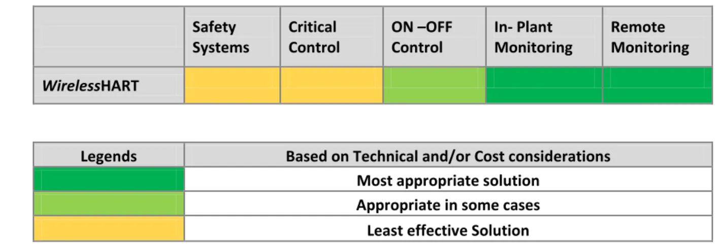
For example, the process design engineer can use a set of criteria as shown in below Table 5-1: Example Criteria to identify candidate wireless applications.
Safety Systems Critical Control ON –OFF Control In- Plant Monitoring Remote Monitoring
WirelessHART
Legends Based on Technical and/or Cost considerations
Most appropriate solution
Appropriate in some cases
Least effective Solution
Table 5-1: Example Criteria
Ideally, candidate WirelessHART applications are identified during the early process design phase during FEED. This could be during Process Flow Diagram (PFD) and Piping and Instrument Design (P&ID) Diagram development. However, if an early decision is not taken, this should not preclude the use of the technology later in the project.
The basis for design should be shared amongst all stakeholders so that other technical design authorities can identify potential wireless applications and benefit from the installed wireless infrastructure. Furthermore, this process ensures consistent implementation across all design authorities and allows for an efficient decision process to use wireless.
Below are the key points to consider while setting the guidelines:
• Determine which categories of points are eligible to be wireless: safety, control, monitoring, and local indication.
• Determine if new users are eligible for automation: process efficiency, maintenance, reliability, asset protection, health/safety/environmental, and energy management.
• Determine percent spares required and necessary spare capacity.
• Factor in distance considerations between gateways and wireless field devices. Distance considerations are elaborated on in Section 0, Designing.
• Consider the WirelessHART field network backhaul requirement, if required.
5.7.2
Specifications
Specifications for WirelessHART field devices are significantly the same as wired HART devices. See Appendix B WirelessHART vs. Wired HART Comparison for key differences. HART instrumentation specifications are the foundation for WirelessHART specifications. The fundamental differences with regard to the ISA-20 specifications are output signal, power supply, update rate, protection type/enclosure. Specifications not included in this short list are
either included with the IEC 62591 WirelessHART standard, small deviations from HART that require optional attention for the specification process, or are unique to a field device vendor.
Specification Field Typical HART Specification Typical WirelessHART Specification
Output Signal 4-20 mA HART IEC 62591 WirelessHART
Power Supply 24V DC Loop Powered Intrinsically Safe Battery
Update rate 1 second 1 second to 60 minutes
Protection/Enclosure Explosion Proof Intrinsically Safe
Table 5-2: Differences Between Wired and WirelessHART
IEC 62591 WirelessHART is an international standard for wireless process devices. The standard includes advanced provisions for security, protocol, and other features and therefore specification of such attributes covered in the standard are not necessary.
Appendix A provides example specifications for a WirelessHART gateway and wireless adapter that can be generically specified as transceivers/receivers.
5.7.3
Proof of Concept Test
WirelessHART is well established in a comprehensive range of process plants and environments. On occasion it may be necessary for the purposes of demonstration and to establish familiarity, to conduct a proof of concept test to familiarise stakeholders to the technologies capability and applications, this can be done in a workshop setting.
5.8
Initial Design Review
Upon completion of site plot plan review, the report results gathered from various
WirelessHART tools, proof of concepts and compliance to customer requirements shall be discussed with all stakeholders. Any requirement changes, deviations or assumptions shall also be discussed with the stakeholders. Since WirelessHART is extremely flexible it always easy to incorporate changes to the architecture.
6
Execute
During the Execute phase (Detailed Design and Testing) of a project, the engineer must account for WirelessHART devices per the guidelines established in the FEED, add wireless specific fields to the project database, and follow wireless field network design procedures to ensure best practices are implemented.
This section addresses the following aspects of Execute Detail design phase.
• Design Resources
• Design Guidelines
• Wireless Field Networks Design Description
o Key Components of the Wireless Field Network Solution o Wireless Devices and Gateway
o Wireless Device Selection Criteria and Datasheets
• Field Network Deployment
o Project Environmental Considerations, Intrinsic Safety Requirements o Equipment Environmental Specification
o Radio Regulatory Compliance
o Plant Areas and candidate Areas for Further Wireless Deployments
• Host System Interface
o Host/DCS components and architecture o Network Identification
o Asset Maintenance software Interface
• Third Party Interface
• Wireless Field Network Infrastructure
o Typical Architecture, o Equipment Location
o Cable Specifications and Types
o Field Data Backhaul Philosophy and Backhaul Specification
• Design philosophy deployment
o Topology, Wireless Field Network Control Philosophy o Monitoring, Closed Loop Control
o Module Design and Scan Rates o Alarm and Status Information
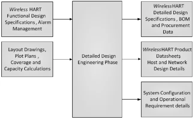
Following Figure 7 shows the inputs and outputs of the Detailed Design in Execute phase.
Figure 7: Execute-Detailed Design Phase
6.1
Wireless
HART Field Network – Design Engineering Overview
There are three key steps for designing a network.1. Scope – Decide if you need to divide wireless field networks by process unit or subsection of a process unit. Factors include:
II. Update rates need for wireless devices III. Capacity of gateway
2. Design – Apply design rules to ensure optimum connectivity.
3. Fortify – Identify and correct any potential weaknesses in the network design.
The three basic steps apply for all process environments in all industries, although the context may vary slightly depending on the physical structure of the process environment. The basic steps also apply regardless of the vendor of the WirelessHART device. Since WirelessHART networks become stronger, the more devices are added, the Scope step is the most critical for high density applications.
WirelessHART is designed for both control and monitoring applications. Refer section 2 Project Concepts for detail recommendations on using wireless control system and devices.
In general, control with WirelessHART is appropriate for most cases of open loop control that require manual interaction with the process and some cases of supervisory control for set point manipulation and process optimization. Applications for closed loop regulatory control of a critical loop may be evaluated case by case.
6.2
Design Resources
See the Design Resources Appendix for more information. Contact your respective
WirelessHART vendor for automated design tools to aid:
• Wireless Network Planning
• Network Design
• Gateway Capacity Planning
• Device Type Availability and Battery Life Estimation
6.3
Wireless Device Selection based on process measurement
WirelessHART devices are available for various process measurement applications.
6.3.1
Process Monitoring & Control
• Hard to reach locations
• Process efficiency calculations
• Better insight into process
• Ad-hoc measurements
• Additional measurements from multivariable devices
6.3.2
Equipment measurement
• Vibration
• Corrosion
• Oil pressure
• Air flow
6.3.3
Health and Safety Systems
• Gas Detectors
• Analyzers
6.3.4
Environmental
• Steam traps (energy usage)
• Water / Discharge Treatment
• Flow
• pH
• Stack emissions
• Relief valves
WirelessHART devices can be deployed in harsh environment and hazardous areas. Table 6-1:
WirelessHART Applications below lists few examples of WirlessHART deployment. For a comprehensive list of applications, refer to the Emerson Wireless Application Guide which is available through your local Emerson project specialist.
WirelessHART Applications
Spray Water Filter Plugging/Vapour Stream
Remote Pumps Heat Transfer
Moving Rail Cars Control Network Bridging
Rotating Reactor Air Compressor
Wellhead/Heat Exchangers Gross Oil Production Flow Temperature Profiling/Tank Level Blast Furnace Hearth Gross Production Headers Steam Trap Monitoring Combustion Engine Emissions Overfill Protection at Refinery
Turbine Units State Regulation Compliance
Pump Vibration Tank Farm Management
Rotating Lime Kiln Boiler Box Temperature Profile Plugged Filter Detection Ash Dewatering Bin
Wellhead Maintenance Steam Flow Accounting
Refinery Management Crude Distillation Unit Steam monitoring
WirelessHART Applications
Steam Cracker Diesel & Kerosene production monitoring Treated Water Usage Rotating Calciner
Filter Condition Pipeline Leak Detection
Pipeline System Compressor Emissions Compliance Remote Storage Tanks Rotating Roaster
Cold Box Boiler and heater gas flow
Steam Distribution Lines Bitumen Tank Farm
Rotating Alumina Kiln Gas & Diesel Tank Inventory Management Power Industry Applications NOx Emissions
Storage Tank Monitoring System Critical Oil Movement Tank Gauging
Pipelines Sugar Bin Motor Monitoring
Fuel Supply Systems Gas Storage
Remote Tanks Steam Trap & PRV Monitoring Table 6-1: WirelessHART Applications
6.4
Design Criteria Development
Each wireless network field should be scoped to a single process unit.
Minimize the number of hops to the Gateway in order to reduce latency. A minimum of five wireless instruments should be within effective range of the Smart Wireless Gateway.
Each device in the network should have a minimum of three devices with potential communication paths. A mesh network gets its reliability from multiple communication pathways. Ensuring each device has multiple neighbours within range will result in the most reliable network.
Have 25 percent of wireless instruments in the network within range of Smart Wireless Gateway. Other enhancing modifications include creating a higher percentage of devices within effective range of the gateway to 35 percent or more. This clusters more devices around the gateway and ensures fewer hops and more bandwidth available to WirelessHART devices with fast scan rates.
6.5
Identify Candidate Measurement Points
Using the wireless guidelines established in the FEED, the design engineer should segregate all points in the project database to identify the eligible wireless IO points. For example, if monitoring is deemed to be an eligible category, these points should be sorted from the control and other points. Afterwards, further requirements of the field devices can be applied. For example, some control and monitoring points may be excluded from wireless eligibility because
the required update rate exceeds either the desired life of the battery or the capability of the field device.
Typical control update rates may require 1 second or faster. There is a trade-off for wireless devices between update rate and battery life; the faster the update rate, the lower the battery life will be. It is recommended that the update rate of the measurement shall be three times faster than the process time constant. As an example, a typical update rate for measuring temperature changes with a sensor inside a thermowell can be 16 seconds or longer given how much time is required for heat to penetrate the thermowell.
6.6
Database Field for Wireless Network Assignment
Each wireless field device must be assigned to a specific gateway that manages a specific wireless field network.
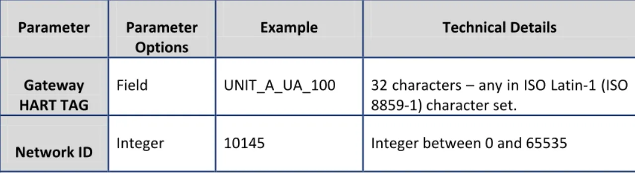
Each gateway will manage its own wireless field network and can have an assigned HART Tag like any HART device. Each wireless field network in a plant must have a unique Network ID to prevent devices from attempting to join the wrong network. In order to ensure the desired security level is achieved, a decision must be made whether to use a common join key for all devices in a given field network, or unique join keys for each field device. The combination of these two parameters provides identification and authentication down to the field device. Below
Table 6-2: Definitions of Network Parameters When Using a Common Join Key shows examples of a gateway HART TAG, Network ID and Common Device Join Key.
Table 6-2: Definitions of Network Parameters When Using a Common Join Key
The Join Key is the most important parameter for implementing security. User can know the Gateway HART TAG and the Network ID for the network the gateway manages, but without a Join Key, a wireless field device cannot join the network. The design engineer should be sensitive to the security policies of the design firm and the security policies of the future owner/operator and, as a minimum, treat the Join Key with the same sensitivities as a password for a server to a DCS or database. For this reason, storing the join key as a field in a design database is not prudent.
Parameter Parameter
Options Example Technical Details
Gateway
HART TAG Field UNIT_A_UA_100 32 characters – any in ISO Latin-1 (ISO 8859-1) character set.
Fields should be added to the project database to indicate that a field device is wireless and its association with a gateway using the gateway HART TAG or other labelling convention. Parameters required to be managed confidentially should be controlled in a secure means in alignment with established security policies. Staff members with IT security or process security responsibilities are well suited to provide consultation into the handling of sensitive information.
Finally, the design engineer should be aware of available WirelessHART devices. Many come with multiple inputs that can satisfy the total number of points in a project with fewer devices. For example, several vendors have a multiplexed WirelessHART temperature device that reduces costs.
6.7
Network Design
Once wireless candidate devices have been identified in the instrument database, the field network design can begin.
Ideally wireless points should be organized by process unit and by subsection of process unit as typically depicted in the master drawing. This information can be used to determine the number of gateways required. Additional gateways can be added to ensure spare I/O capacity per guidelines or other project requirements. From here, the gateways should be logically distributed throughout the process unit like marshalling panels. Wireless field devices should be assigned to the closest gateway or to the gateway that is assigned to the process unit subsequent to the unit where the field devices reside. Once this is complete, network design best practices should be checked to ensure reliability of the network. This will be covered in detail in the WirelessHART Field Network Design Guidelines.
Drawings should be created per existing standards. In most instances, a wireless field device is treated identically to a wired HART device. Most drawings do not indicate wires or the type of communication protocol, thus nothing unique needs to be done for wireless field devices. The section 10 Ancillary WirelessHART Devices provides examples unique to WirelessHART such as gateways and wireless adapters. Fundamentally, it will be up to the design engineer to adhere to or provide a consistent convention that meets the needs of the contractor and the owner operator as is true for wired HART projects.
Existing HMI (human-machine interface) design guidelines for integration also apply to wireless with no change required since data points connected from the gateway into the host system are managed like any other source of data.
6.7.1
Wireless
HART Field Network - Design Guidelines
The WirelessHART network specification enables a reliable, secure, and scalable architecture. Contrary to legacy systems and point-to-point wireless networks, WirelessHART is a truly scalable automation technology that gets more robust as more devices are added to an existing network. Design guidelines support the deployment of small networks with less than 10
WirelessHART devices for monitoring and control, as well as installations supporting thousands of devices.
This section includes recommendations to support the long-term, sustainable adoption of wireless applications including WirelessHART as well as Wi-Fi, Wi-Max, and more.
The best practices for network design are applicable for networks operating with mix of
WirelessHART devices for monitoring and control with update rates from 1 seconds to 3600 seconds (60 minutes). A site survey is not normally required or even possible in the case of a Greenfield site. For an overview on spectrum usage refer to Appendix D Wireless Spectrum Governance.
6.8
Scoping
The same design rules that govern the segmentation of wired HART networks apply to
WirelessHART. From a very simple perspective, all process facilities have an architecture that organizes the infrastructure as well as the automation and the people. WirelessHART not only self-organizes to the process environment, but also to this inherent organization of the process facility. For example, the process facility shown in Figure 8 is organized into 7 process units that are separated by roads.
Figure 8: Example Process Facility
If the process facility is not an outdoor production environment, there is still a natural organization that should be used for scoping networks. For example, power plants and biopharmaceutical manufacturing facilities are typically completely enclosed with multiple
floors. One option is to scope WirelessHART field networks to a floor. If there are 7 floors, then there are potentially seven WirelessHART networks.
The benefits of scoping a WirelessHART field network to a process unit are:
• Aligns the data flow from the WirelessHART device through the gateway to the Host System with existing data architecture.
• Aligns WirelessHART tagging convention with wired HART tagging convention.
• Aligns WirelessHART documentation practices with the process unit and support device location. If you know device A is on Network A and in process unit A, then one should not look in process unit B to find device A.
• Aligns work processes of managing WirelessHART device lifecycles with wired HART life cycles including organizational responsibilities.
• Sets reasonable expectations for range between WirelessHART devices. Most process units do not have a footprint greater than a few hundred feet (<0.2km) by a few hundred feet (<0.2km).
While scoping the number of networks and gateway placement, the design engineer should factor in considerations for gateway capacity and spare capacity. At a minimum, each process unit should have its own gateway with spare capacity for problem solving in real time. If a project is small and application focused and total numbers of IO points are less than the capacity of gateway, then typically a single gateway is required. If the project is large or has wireless field devices with update rates faster than 4 seconds, then following is the process of determining the total number of gateways and modifying the scope of a network.
1. Filter the Instrument Index List by process unit and determine how many I/O points are in each process unit that are wireless so that the WirelessHART networks can be segmented by process unit.
a. For example, out of 700 total I/O points, let’s assume process unit A has 154 wireless points requiring 154 WirelessHART devices. We need to determine how many gateways are needed.
Note: Some WirelessHART devices support more than 1 wireless point and so there may be instances when fewer devices are required to satisfy the number of measurement points. A key example is a WirelessHART temperature transmitter where 2 or more temperature elements are used as inputs. Networks can support a mix of device types and update rates. The method outlined here is a simple method that determines max capacity with very limited design information.
2. Identify the necessary update rate of each WirelessHART device to meet the specifications of the application as well as battery life.
a. Typical WirelessHART devices can update from 1 per second to once per hour.
b. Update rate should be 3-4 times faster than the time constant of the process for monitoring and open loop control applications.
c. Update rate should be 4-10 times faster than the time constant of the process for regulatory closed loop control and some types of supervisory control.
d. The faster the update rate, the shorter the battery life. Use an update rate that meets the needs of the application, but does not oversample in order to maximize battery life.
e. Update rates faster than 4 seconds can impact the total number of wireless devices that can be put on a gateway. Consult the specification of the gateway vendor for additional constraints and consultation.
3. Determine the capacity of the gateway determined by the maximum update rate to be used in the network. Be conservative and assume all devices are operating at the same, fastest update rate network for the purpose of estimation. Example output: 100 WirelessHART devices per gateway if all devices are updating every 8 seconds or slower and the gateway can support 100 devices at 8 seconds.
4. Determine and apply any guidelines on spare capacity. If the design rules for the project state that I/O components should have 40% spare capacity, then note this value for the following calculation.
5. Use the following calculation to determine the number of gateways.
# gateway=ROUNDUP((Total WirelessHART devices in process unit)/(gateway capacity*(1-spare capacity requirement) ))needed:
# 𝑔𝑎𝑡𝑒𝑤𝑎𝑦
=𝑅𝑂𝑈𝑁𝐷𝑈𝑃(𝑔𝑎𝑡𝑒𝑤𝑎𝑦𝑇𝑜𝑡𝑎𝑙𝑐𝑎𝑝𝑎𝑐𝑖𝑡𝑦 ∗𝑊𝑖𝑟𝑒𝑙𝑒𝑠𝑠𝐻𝐴𝑅𝑇(1− 𝑠𝑝𝑎𝑟𝑒𝑑𝑒𝑣𝑖𝑐𝑒𝑠𝑐𝑎𝑝𝑎𝑐𝑖𝑡𝑦𝑖𝑛𝑝𝑟𝑜𝑐𝑒𝑠𝑠𝑟𝑒𝑞𝑢𝑖𝑟𝑒𝑚𝑒𝑛𝑡𝑢𝑛𝑖𝑡 ))
Note: Some gateway vendors have advanced capacity planners that can provide detailed capacity estimate based on the required updates of individual update rates. WirelessHART networks can support a mix of device types and update rates. The method outlined here is a simple method that determines max capacity with very limited design information.
For the example above, three gateways are needed.
#gateway = ROUNDUP(100∗154(1−0.40)) = 3
This formula can be entered into Microsoft Excel.
6. Scope the number of required gateways into subsections of the process unit. If more than one gateway is needed per process unit, then the design engineer should segment the networks such that the gateways are distributed in the field like marshalling panels and junction boxes. In Figure 9, the master drawing, the process unit has 16 subsections labelled L-2 through L-17 that should be logically segmented for coverage by gateways. Not every gateway needs to have the same number of wireless points. If redundant gateways are to be used, then double the number of gateways based on the output from the above formula.
Figure 9: Process with 3 WirelessHART Networks and good gateway placement
This example shows three WirelessHART gateways supporting three WirelessHART networks in the same process. This is analogous to having three FOUNDATION Fieldbus segments in the same process unit. In this example, the process unit subsections were grouped horizontally instead of vertically to minimize the distance of the process unit. A key consideration is that the gateways, regardless of manufacturer should always be in the process space for which they supply I/O capacity. Below is an image of what not to do.
Figure 10: Process with 3 WirelessHART gateways and poor gateway placement
Do not place all gateways in the same location just because connecting into the host system is convenient. The next section on network design will show that this is inefficient and can lead to unreliable networks in the long term. The gateway should be centralized to the field network to maximize the number of connections to wireless devices.
WirelessHART networks can be logically aligned with existing documentation and automation engineering practices following this procedure.
Key things to remember:
• Scoping is the most important design rule. Use it to ensure wireless capacity, long term scalability, high reliability, and alignment of WirelessHART devices and management with existing process facility, organization, and work practices.
• Every WirelessHART gateway in a facility must have a unique Network ID to properly segment the WirelessHART field networks.
• The output from the scoping phase should be a scaled drawing showing the relative locations of assets and processes to be automated and potential integration points for the WirelessHART gateways.
6.9
Detailed Design Specifications
Upon completion of site study report review and considering the control system requirements, Detail Design Specifications shall be prepared. Detail design shall cover overall wireless mesh architecture including the detailed network infrastructure, WirelessHART devices
and network hardware and software specifications, network integration method, network security specification, network monitoring tools and documentation requirements.
6.9.1
Designing
Effective Device Range
The following design rules are intended to be very conservative and are based on real-world deployments of WirelessHART field networks. The effective range of a device is the typical linear distance between WirelessHART field devices when in the presence of process infrastructure. Typically, if WirelessHART devices have no obstructions between them, have clear line of sight (LOS), and are mounted at least 6 feet (2 meters) above the ground, then the effective range with 10 mW/10 dBi of power is approximately 750 feet (228 m). Obstructions decrease the effective range. Most process environments have high concentrations of metal that reflect RF signals in a non-predictable manner bouncing the signal off of the metal of the surrounding environment. The path of an RF signal could easily be 750 feet (230m) even though the neighbouring device separation is only 100 feet (31m) away. Below are three basic classifications for effective range in the process environment.
• Heavy Obstruction – 100 ft. (30 m). This is the typical heavy density plant environment. Cannot drive a truck or equipment through.
• Medium Obstruction – 250 ft (76 m). This is the less light process areas, lots of space between equipment and infrastructure.
• Light Obstruction – 500 ft (152 m). Typical of tank farms. Despite tanks being big obstructions themselves, lots of space between and above makes for good RF propagation.
• Clear Line of Site – 750 ft (228 m). The antenna for the device is mounted above obstructions and the angle of the terrain change is less than 5 degrees. Some
WirelessHART vendors provide options and techniques for obtaining even further distances for long distance applications.
These values are practical guidelines and are subject to change in different types of process environments. Conditions that significantly reduce effective range are:
• Mounting field devices close to the ground, below ground, or under water. The RF signal is absorbed and does not propagate.
• Mounting field devices inside or outside of a building relative to the main network and gateway. RF signals do not propagate well through concrete, wood, etc. Typically, if there are wireless devices nearby on the other side of the enclosure, no special design rules are needed. If there is a high volume of WirelessHART devices isolated from the network by an enclosure, consider scoping a network inside of the facility. Small, fibreglass instrument and device enclosures often deployed in very dirty or harsh environments show minimal impact on propagation of RF signal and can be used. Large Hoffman-style metal enclosures will prevent RF signals and are not recommended without additional engineering considerations.
The low power nature of WirelessHART devices allow operation for several years without replacing a battery module, but also limit the output power of the radio and maximum range. Because WirelessHART devices can communicate through each other to send messages to the gateway, the self-organizing mesh naturally extends the range beyond that of its own radio. For example, a wireless device may be several hundred feet or meters away from the gateway, but power efficient “hops” through neighbouring devices closer to the gateway ensure reliable, extended range.
The effective range is used to test the validity of network design by applying the following design rules.
There are 4 fundamental, recommended network design rules.
1. Rule of 5 minimum – Every WirelessHART network should have a minimum of 5
WirelessHART devices within effective range of the gateway. Networks will work properly with less than 5 WirelessHART devices but will not benefit from the intrinsic redundancy of a self-organizing mesh network and may require repeaters. In a well formed, well designed network, new WirelessHART devices can be added to the interior or perimeter of the network without affecting operation or extensive consideration for design.
Figure 11 is a simple design example. The network has been properly scoped to a process unit and 4 WirelessHART devices have been placed with a gateway on a scaled process drawing. The red circle around the gateway represents the effective range of the gateway. We see in this example, the Rule of 5 Minimum is broken in that there are only 4 devices within effective range of the gateway. This network will likely perform to specification, but it is optimal to fortify for long term scalability and reliability by adding more devices.
Figure 11: Process With Rule of 5 Broken
2. Rule of 3 – Every WirelessHART device should have a minimum of 3 neighbours with in effective range. This ensures there will be at least 2 connections and the potential for connections to change with time.
Continuing on from the previous example, we fortified the network by adding another field device within the effective range of the gateway and added another device as another measurement point. Now the red circle represents the effective range of the WirelessHART device that does not have 3 neighbours. For reliability, it is essential for every WirelessHART to have 2 paths during operation to ensure a path of redundancy and diversity. The Rule of 3 when designing ensures concentration of devices.
Figure 12: Process With Rule of 3 Broken
3. Rule of Percentages - Every WirelessHART network with greater than 5 devices should have a minimum of 25% of devices within effective range of the gateway to ensure proper bandwidth and eliminate pinch points. WirelessHART networks can work with as little as 10%, and actual implementation may yield less than 25%, but experience shows this is a practical number. Example, a 100 device network implies 25 within effective range of the gateway.
I. Networks with greater than 20% of wireless devices with update rates faster than 2 seconds should increase the percentage of devices with in effective range of the gateway from 25% to 50%.
4. Rule of Maximum Distance – Wireless devices with update rates faster than two seconds should be within 2 times the effective range of wireless devices from the gateway. This rule maximizes speed of response for monitor and control applications requiring high-speed updates.
Applying Network Design Recommendations
WirelessHART devices are located according to their process connection. Only an approximate location is required for location on the scaled drawing since the self-organizing mesh technology will adapt to conditions as they exist and change from the point of installation. The design rules ensure a concentration of WirelessHART devices for ample paths between the devices. This allows the self-organizing mesh to optimize networking in a dynamic environment.