http://www.sciencepublishinggroup.com/j/ajdmkd doi: 10.11648/j.ajdmkd.20170201.11
Analysis of Bio-inspired Kinematic Patterns
Pectoral Fin
with Shape Memory Alloy (SMA)
Mohammad Eftekhari
1, *, Saeed Rahmanian
2, Pezhman Moradi
21
Department of Mechanical Engineering, Isfahan University, Isfahan, Iran 2
Department of Mechanical Engineering, Jahrom University, Jahrom, Iran
Email address:
*
Corresponding author
To cite this article:
Mohammad Eftekhari, Saeed Rahmanian, Pezhman Moradi. Analysis of Bio-inspired Kinematic PatternsPectoral Fin with Shape Memory Alloy (SMA). American Journal of Data Mining and Knowledge Discovery. Vol. 2, No. 1, 2017, pp. 1-7.
doi: 10.11648/j.ajdmkd.20170201.11
Received: December 13, 2016; Accepted: January 5, 2017; Published: January 30, 2017
Abstract:
Pectoral fins have received the attention of many researchers because of their important role in maneuverability underwater in the recent years. This paper presents the study of a novel flexible robotic-fin actuated and the swimming propulsion by Shape Memory Alloy (SMA) inspired by a Koi Carp. In this paper, the morphological and mechanics parameters of a koi Carp pectoral fin from a carp is first studied. The motion of the pectoral fins is analyzed, which are difficult to reproduce by artificial pectoral fins and descending and ascending, the five basic gestures of the robotic fin are well achieved by the coordinating control of the fin base and fin rays, which are relaxation, expansion, bending, cupping and undulation. Secondly, a simplified theoretical model of the SMA fin plate is derived, thermodynamics of the SMA plate and the relationship between curvature and phase transformation are analyzed. Thirdly, Dynamic modeling of a flexible SMA tail, several simulations and model experiments are conducted according to the previous computation and analyses. Consequently, the five basic gestures of the robotic fin such as relaxation; expansion; bending; cupping; undulation, are extracted from the 3D grid graph. The results of kinematic of flexible pectoral fins will provide a basis to flexible pectoral fin and butterfly-inspired underwater.Keywords: Biomimetic Underwater Robot, Bio-inspired Pectoral Fin, Fin Patterns, Oscillation,
Shape Memory Alloy (SMA), SMA-Driven Plate, Maneuverability1. Introduction
Zoologists, biologists, and engineers have all examined fish and other aquatic creatures with intense interest, including their specific behavior, swimming pattern, high maneuverability, and efficient design [1]–[5]. The thorough researches on fish physiology and morphology have indicated that the notable swimming propulsion efficiency is entirely due to not only orchestrated motion of multiple fins, but also their flexible, diverse and complex three-dimensional movements, the superiority of the flexible fins cannot be matched by any bionic fins [6, 7]. In previous studies, many fish-like underwater robot were developed using various kinds of, such as Shape Memory Alloy (SMA) [8]–[10], Ionic Conducting Polymer Film (ICPF) [11], [12], and Ionic Polymer Metal Composite (IPMC) [13], [14] have
examined the fluid-structure interaction and force generation by pectoral fins of a fish during labriform swimming.
Webb [21] and Blake [22] performed some theoretical modeling of pectoral fins-based swimming of live fish, which provides useful tools for calculating hydrodynamic forces acting on the pectoral fins. There have been a variety of robotic fish reported that involve pectoral fins. Most of these use rigid, oscillating fins [23], [24]. The existing simulation research on the kinematics of pectoral fins mainly concerns the analysis of kinematic parameters in fish steady swimming [25– 29]. Whereas pectoral fins play a more important role in fish maneuvers, especially during retreating and hovering [30]. The present work is concerned with the kinematics study on Koi Carp, whose swimming is a typical carangiform, possessing a great maneuverability and a high swimming efficiency.
The paper is structured as follows. Section 2 proposed the mechanical characteristics of a pectoral fin of Koi carp comprehensively. Subsequently, the simulation of SMA driven plate is described and discussed in section 3. The theoretical analysis of the SMA plate, for instance, thermodynamics of SMA plate, relationship between curvature and phase transformation of SMA plates are investigated in section 4. Lastly, the paper ends with the conclusion section.
2. Morphology and Mechanical
Characteristics of a Pectoral Fin of
Koi Carp
Carp is a kind of typical carangiform fish, which has a highly effective swimming ability with the aid of its pectoral fins. Thus, as it can be seen in Table 1, our concentration is based on taking carp as a sample in order to measure the morphological parameters of the fin.
Table 1. Morphological features of a carp pectoral fin.
Morphological features Value
The body length of the carp (mm) 200
The area of the pectoral fin (mm2) 680
The number of fin rays belongs to the fin 14
The length of the longest fin ray (mm) 34
The length of the shortest fin ray (mm) 13
Figure. 1 demonstrates manifestly the marked points of both sides ought to be aligned with the longitudinal axis of the fin ray. As it can be seen from Figure. 1, the pectoral fin of Koi Carp [32] consists 14 fin rays, in which 20 black dots on one side of pectoral fin are marked points. It is worth noting that the fin ray adjacent to dorsal fin below neutral condition is dorsal leading ray while the pectoral fin adjacent to ventral fin underneath neutral condition is the ventral leading ray. Additionally, the outer edge of pectoral fin is the part of pectoral fin away from the fish's body whereas the inner edge of pectoral fin indicates the section of pectoral fin near the fish's body (rigid body).
The phase difference of two adjacent sample points in a sinusoidal function is crucial to satisfy the requirement,
according to Shannon’s sampling theorem [33] as:
∆ (1)
Moreover, the phase difference of two nearby fin rays in a pectoral fin can be written as follows:
Δ (2)
In which n expresses the number of fin rays and stands the wave number of undulation motion. By combining Equation (1), (2), the relationship between wave number and the number of fin rays can be expressed by:
4 1 (3)
Based on the equation (3), as a minimum, 5 markers are essential so as to simulate a thorough cycle of undulation motion. In this work, five markers along the outer edge of fin rays (see Figure. 1 for the numbers of 1, 4, 7, 9, and 12) are opted respectively. Hence, the 3D motion profiles of the pectoral fins can be achieved by using simulation processing.
As is evident, the movements of the pectoral fins are sophisticated which made researchers to reproduce artificial pectoral fins. Luckily, from plentiful images of the pectoral fins, for example, cruising, turning, retreating, ascending, descending, and the five simple gestures of the bio-inspired fin are well achieved in Figure. 2 [31]. Similarly, Lauder’s group [34, 35] perceived some interesting patterns of koi carp swimming.
Figure 1. Illustration of the marked pectoral fin. Model of the koi Carp pectoral fin.
Figure 3. Bending stiffness of the respective fin rays. The standard deviations are in the range of (0.002 to 0.031) 10-4N.m-2.
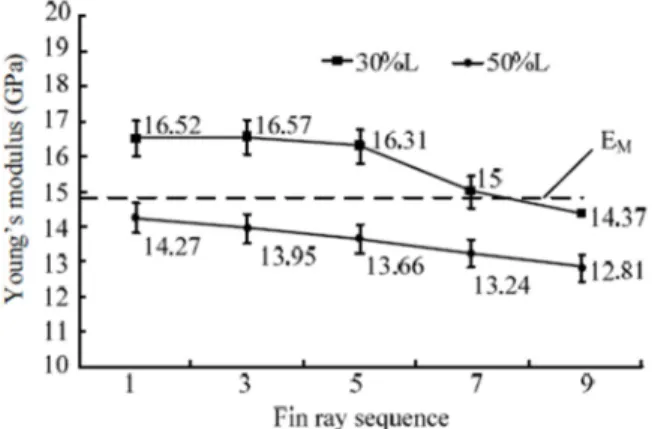
Figure 4. Young’s modulus of the respective fin rays. The standard deviations are in the range of (0.04 to 0.257) GPa. EM=14.8 GPa, EA=39.3 GPa.
Figure 5. Oscillation of the SMA-driven plate.
The mechanical properties of a fin ray are important for developing a robotic fin. In order to obtain the distribution of bending stiffness and Young’s modulus of the pectoral fin ray, regarding the base side to the distal side, five fin rays (Figure. 1.) are chosen carefully for conducting the test. The stiffness of one location is calculated for five times with changing force, and the standard deviations are also obtained. The simulation results are shown in Figures. 3 and 4.
It can be seen from Figures. 3 and 4 that both bending stiffness and Young’s modulus diminish from Fin Ray 1-9. It should be emphasized that Young’s modulus of 30% length location was approximately 1.1 times as that of 50% length location. Both bending stiffness and Young’s modulus of SMA plates are approximate to that of the carp’s fin rays, which are presented in Figures. 3 and 4. In these figures, KM
and EM denote bending stiffness and Young’s modulus of
SMA plates in the martensite phase. However, EA denotes
Young’s modulus of SMA plates in austenite phasing. On the other hand, the SMA plates are stiffer when they actuate.
3. Simulation of the SMA-Driven Plate
cools, the SMA driven plate will return straight. By successively heating SMA wires on both sides of the plate with two PWM currents with phase difference, the SMA plate can bend and oscillate [36]. It is worth mentioning that the motion of the SMA-driven flexible plate is related to the dynamical constitutive equation of SMA, the thermodynamic between SMA wires and their environment, the dynamics related to large deformation flexible beam, two SMA wires, and hydrodynamics. The dynamics of flexible plates embedded with SMA wires are tiresome to model. Hence, the diameter of SMA wires was estimated through static equilibrium, and determine the range of some key parameters by simulation, such as the diameter of SMA wires and the current that passes through the SMA wires.
a) Control of the bending direction of the SMA-plate by heating SMA wires. A, B denote SMA wires on the top and bottom surfaces of the plastic plate, respectively. θ denotes the oscillation angle of SMA-driven plate, which can be measured by the angle between the horizontal line and the tangent to the tip point of SMA-driven plate.
b) Time sequence of the heating current for SMA wires A and B.
4. Theoretical Analysis of the SMA Plate
4.1. Thermodynamics of SMA Plate
Usually, SMA wires are heated by electric current. However, the SMA plate has a bigger volume, and needs more energy than SMA wires. As a result, it is inappropriate to heat the SMA plate directly with electric current.
Three assumptions are made in the thermodynamic analysis of SMA plate: (4) The PVC tube is thin. It covers the enamel-insulated copper wire and the SMA plate closely and tightly. The tube, copper wire and SMA plate can be considered as an integrated plate. (5) Radiation can be ignored because of little amount of radiation of the tube, copper wire and SMA plate. (6) The connection between the integrated plate and water is presumed as the only way to transfer heat from the plate to environment.
When the SMA plate is heated, the energy balance is expressed as:
(4)
! "#$%&'#$%&(
) * (5)
+ ,45 - . /0/12*3
46 (6)
+457, - . /0/12*3
46 (7)
+ , - . '#$%&(
) /12*3
45(
46 (8)
+ ℎ .>>65 22/ 03:1;− 1 =/* (9)
where Ei, Esma, Epvc, Ewire, Econ, and Eph denote electric energy,
the heat change of SMA, the heat change of PVC tube, the
heat change of copper wire, convection energy between plate and water, and transformation latent heat of SMA, respectively; i denotes heating current through copper wire; λwire denotes electric resistivity of the copper wire; cwire, csma
and cpvc denote the thermal capacities of copper wire, SMA
plate and PVC tube, respectively; ρwire, ρsma and ρpvc denote
the densities of copper wire, SMA plate and PVC tube, respectively; lwire, lsma and lpvc denote the effective lengths of
copper wire, SMA plate and PVC tube, respectively; d and w denote the depth and width of the SMA plate, respectively; Ts denotes the environment temperature; Tf, Tf1 and Tf2 denote
the final temperatures of SMA plate, PVC tube and enamel-insulated copper wire respectively during the martensite reverse transformation process. ts and tf denote the start moment and finish moment of the heating process, respectively; hw denotes the equivalent convective heat transfer coefficient.
The cooling process of SMA plate is a natural convective phenomenon. The energy exchange during the cooling process is given by:
0 (10)
+ ,45 - . /0/12*3
46 (11)
+ , - . '#$%&(
) /12*3
45(
46 (12)
+457, - . /0/12*3
46 (13)
+ ℎ .>>65 22/ 03:1;− 1 =/* (14)
For the sake of convenience, we consider hw as a constant in both heating and cooling processes. From Eq. (4) to Eq. (14), the energy exchange can be estimated in both heating and cooling processes. However, it is difficult to obtain an accurate result through an analytic calculation, so we conduct a simulation to obtain the actuation time of the SMA plate in both heating and cooling processes.
4.2. Relationship Between Curvature and Phase Transformation of SMA Plates
transformation of SMA plates is described as [40, 41]
@ABC 21 − D3@ E (15)
where D denotes the martensite volume fraction which represents the degree of the martensite phase transformation. kmax denotes the trained maximum curvature, while kSMA
denotes the curvature in phase transformation. When D equals to 1, the phase transformation has not yet started, and the curvature is zero, while D equals to 0, the phase transformation has finished, and the curvature has reached the predefined one. So, D is defined as:
D213 FG
H I2JKJL3 DM (16)
In the cooling process of SMA, the parameters of Eq. (16) are:
1N B6HB5 (17)
O BP
6 B5 (18)
In the heating process of SMA, the parameters of Eq. (16) are:
1N C6HC5 (19)
O C P
5 C6 (20)
in Eqs. (17) – (20), Ms, Mf, denote the starting and finishing temperatures of martensite phase transformation; As, Af the starting and finishing temperatures of austenite phase transformation, respectively; β is determined empirically. In Eq. (16), D a and D b are constants.
5. Swim by the Pectoral Fins
In this test, the wire-driven caudal fin is kept still. The pectoral fins are controlled by the two parameters 5f1 and 5fe in one movement circle. The horizontal plane was set as the initial position of the fins, thus the original values of 5f1 and 5fe are both 0°. When the power stroke adduction begins, the fin was vertical. We control the feathering angle 5fe=90° and the flapping angle 5f1 increasing quickly from 0°to the maximum. The water was pushed posteriorly, thus generating thrust and moving the fish forward. The recovery stroke abduction begins with a quick feathering motion. The feathering angle is controlled from 90° to 0° so as to reduce the adverse water resistance. Furthermore, using the pectoral fins, the robot fish can swim backward by reversing the fin movement. The pectoral fin motion pattern is fixed and the swimming speed is controlled by the frequency. Results are shown in Figure 6.
From the results, there is discrepancy in forward swimming speed and backward swimming speed. One reason is that the vortex drag of the fish at the two ends is different. The tail is more slender, meaning less vortex drag when swimming forward. Therefore, the forward speed is higher than the backward speed. The proposed model predicts the pectoral fin propulsion reasonably well. Among all the tests, the maximum forward speed of the robot using pectoral fins is 145 mm/s and the maximum backward speed is 115 mm/s.
6. Conclusion and Concluding Remarks
This paper outlines Koi Carp simulation system, and the motion pattern of flexible pectoral fin in retreating. We find that the motion pattern of the pectoral fin is a very complex, which was very difficult to obtain the kinematic patterns of the pectoral fin. Likewise, we demonstrate the angle of the foundation of marked fin rays motion in retreating and the correspondence analysis of the surface area of the pectoral fin. Finally, five motion pattern of pectoral fin are extracted from the 3D grid graph. As the future works could adopt the same simulation system to analyze more maneuvers of flexible pectoral fins, for instance, relaxation, expansion, bending, cupping, and undulation which are very educational and significant to mimic a flexible pectoral fin and butterfly-inspired underwater.
References
[1] Ashok K Kancharala, Michael K Philen, Investigation on the Reduction of Center of Mass Oscillations of Flexible Flapping Fins, Vol. 13, 2016, pp. 544-557
[2] Stacy C. Farina, William E. Bemis, Functional morphology of gill ventilation of the goosefish, Lophius americanus (Lophiiformes: Lophiidae), Vo. 119, 2016, pp. 207-2015. [3] Mathieu Olivier, Guy Dumas, Effects of mass and chordwise
flexibility on 2D self-propelled flapping wings, Vol. 64, 2016, pp. 44-66
[4] R. W. Blake, Fish Locomotion. Cambrige: Cambrige University Press, 1983.
[5] Haghighi, AliReza Shourangiz, Iman Zare, AliReza Fallahi, Hamid Reza Naji, and Amin Bahreini. "Bioinspired micro-robot with micro-actuators ICPF and floating collector Skimmer." In 7th Iranian Conference of Electrical and Electronics Engineering, pp. 133-139. IEEE, 2015.
[6] Ziyu Ren, Xingbang Yang, Tianmiao Wang and Li Wen, Hydrodynamics of a robotic fish tail: effects of the caudal peduncle, fin ray motions and the flow speed, Bioinspiration and Biomimetics, Vol. 11, 2016, pp. 016008
[7] P. W. Webb, “Stability and Maneuverability,” Fish Biomechanics, vol. 23, pp. 281-332, 2006.
[8] Jaronie Mohd Jani a, b, ⇑, Martin Leary a, Aleksandar Subic a, Mark A. Gibson c, A review of shape memory alloy research, applications and opportunities, Materials and Design
56 (2014) 1078–1113.
[9] Shixin Mao, Erbao Dong, Hu Jin, Min Xu, Shiwu Zhang, Jie Yang1, Kin Huat Low2, Gait Study and Pattern Generation of a Starfish-Like Soft Robot with Flexible Rays Actuated by SMAs, Journal of Bionic Engineering 11 (2014) 400–411. [10] Fei Gao, Zhenlong Wang, Yukui Wang, Yangwei Wang, Jian
Li, A Prototype of a Biomimetic Mantle Jet Propeller Inspired by Cuttlefish Actuated by SMA Wires and a Theoretical Model for Its Jet Thrust, Journal of Bionic Engineering 11 (2014) 412–422.
[11] Zakharchenko, Svetlana, and Leonid Ionov. "Anisotropic Liquid Microcapsules from Biomimetic Self-Folding Polymer Films." ACS applied materials & interfaces (2015).
[12] Mizuho Shibata & Norimitsu Sakagami (2014): Fabrication of a fish-like underwater robot with flexible plastic film body, Advanced Robotics, DOI: 10.1080/01691864.2014.944213. [13] Joel J. Hubbard, Maxwell Fleming, Viljar Palmre, David
Pugal, Kwang J. Kim, and Kam K. Leang, Member, IEEE, Monolithic IPMC Fins for Propulsion and Maneuvering in Bioinspired Underwater Robotics, IEEE JOURNAL OF OCEANIC ENGINEERING, VOL. 39, NO. 3, JULY 2014. [14] Diab, Mohamad O., Nizar F. Al Awar, Mirna Atieh, Reem
Abou Marak, Mariam Salloum, Oussama Mustapha, and Nazih Mobayed. "Electromechanical model of IPMC artificial muscle." In Computer Applications & Research (WSCAR), 2014 World Symposium on, pp. 1-5. IEEE, 2014.
[15] Q. Yan, L. Wang, B. Liu, J. Yang, and S. Zhang, “A novel implementation of a flexible robotic fin actuated by shape memory alloy,” Journal of Bionic Engineering, vol. 9, pp. 156-165, 2012.
[16] J. L. Tangorra, N. Davidson, I. W. Haunter, P. G. A. Madden, and G. V. Lauder, “The development of a biologically inspired propulsor for unmanned underwater vehicles,” IEEE J. Ocean. Eng., vol. 23 No. 3, pp. 533–550, 2007.
[17] G. V. Lauder, P. G. A. Madden, R. Mittal, H. Dong, and M. Bozkurttas, “Locomotion with flexible propulsors: I. experimental analysis of pectoral fin swimming in sunfish,” Bioinsp. Biomim., vol. 1, pp. S25– S34, 2006.
[18] Haghighi, Alireza Shourangiz, Iman Zare, Alireza Fallahi, Reza Jahromi Bosheri, Amin Haghnegahdar, and Hamidreza Naji. "Dynamic modeling of flexible tail for bio-inspired dogfish shark (Squalus acanthias)- inchworm with multifunctional locomotion." In 7th Iranian Conference of Electrical and Electronics Engineering, pp. 126-132. IEEE, 2015.
[19] G. Barbera, “Analisi teorica e sperimentale di un sistema di controllo per un veicolo biomimetico boxfish,” Ph. D. dissertation, Universita’ Degli Studi Di Padova, Padua, Italy, 2009.
[20] K. Shoele and Q. Zhu, “Numerical simulation of a pectoral fin during labriform swimming,” Journal of Experimental Biology, vol. 213, pp. 2038–2047, Jun. 2010.
[22] Anthony J Clark, Xiaobo Tan, Philip K McKinley, Evolutionary multiobjective design of a flexible caudal fin for robotic fish, Bioinspiration and Biomimetics, Vol. 10, 2015, pp. 065006.
[23] K. A. Morgansen, B. I. Triplett, and D. J. Klein, “Geometric methods for modeling and control of free-swimming fin-actuated underwater vehicles,” IEEE T Robot, vol. 23, no. 6, pp. 1184–1199, Dec. 2007.
[24] P. Kodati, J. Hinkle, A. Winn, and X. Deng, “Microautonomous robotic ostraciiform (MARCO): hydrodynamics, design, and fabrication,” IEEE T Robot, vol. 24, no. 1, pp. 105–117, Feb. 2008.
[25] Wu G. Measuring the three-dimensional kinematics of a free-swimming koi carp by video tracking method. Journal of Bionic Engineering, 2010, 7, 49–55.
[26] Sitorus P, Nazaruddin Y, Leksono E, Budiyono A. Design and implementation of paired pectoral fins locomotion of labriform fish applied to a fish robot. Journal of Bionic Engineering, 2009, 6, 37–45.
[27] Liu B, Xu M, Wang L, Yang J, Zhang S. Fluid-structure interaction study on a flexible robotic pectoral fin. IEEE International Conference on Mechatronics and Automation, Chengdu, China, 2012, 220–225.
[28] Hu T, Shen L, Lin L, Xu H. Biological inspirations, kinematics modeling, mechanism design and experiments on an undulating robotic fin inspired by Gymnarchus niloticus. Mechanism and Machine Theory, 2009, 44, 633–645. [29] Zhang Y, He J, Low K H. Parametric study of an underwater
finned propulsor inspired by bluespotted ray. Journal of Bionic Engineering, 2012, 9, 166–176.
[30] Tangorra J L, Phelan C, Esposito C, Lauder G V. Use of biorobotic models of highly deformable fins for studying the mechanics and control of fin forces in fishes. Integrative and Comparative Biology, 2011, 51, 176–189.
[31] Qin Yan, Lei Wang, Bo Liu, Jie Yang, Shiwu Zhang, A Novel Implementation of a Flexible Robotic Fin Actuated by Shape Memory Alloy, Journal of Bionic Engineering 9 (2012) 156– 165.
[32] Lei Wang, Min Xu, Bo Liu, Kin Huat Low, Jie Yang, Shiwu Zhang, A Three-Dimensional Kinematics Analysis of a Koi Carp Pectoral Fin by Digital Image Processing, Journal of Bionic Engineering 10 (2013) 210–221.
[33] Oppenheim A V, Willsky A S, Nawab S H. Signals and Systems, 2nd ed, Prentice Hall, Upper Saddle River, NJ, USA, 1997.
[34] Lauder G V, Peter G, Madden A. Fish locomotion: kinematics and hydrodynamics of flexible foil-like fins. Experiments in Fluids, 2007, 43, 641–653.
[35] A. Shourangiz Haghighi, I. Zare. Mohammad Ahmadi Balootaki, Mohammad Orak, Omid Zare. Modeling of Bio-inspired Thunnus Albacares and Inchworm-gammarus with Micro Actuators in One Structure. International Journal of Science and Qualitative Analysis. Vol. 1, No. 3, 2015, pp. 54-63.
[36] Shiwu Zhang, Bo Liu, Lei Wang, Qin Yan, Kin Huat Low, and Jie Yang, Design and Implementation of a Lightweight Bioinspired Pectoral Fin Driven by SMA, IEEE/ASME TRANSACTIONS ON MECHATRONICS, VOL. 19, NO. 6, DECEMBER 2014.
[37] Tanaka K. A thermomechanical sketch of shape memory effect: one-dimensional tensile behavior. Res Mechanica, 1986, 251–263.
[38] Liang C, Rogers C A. One-dimensional thermomechanical constitutive relations for shape memory material. Journal of Intelligent Material Systems and Structures, 1990, 1, 207–234. [39] Choonghee Jo, David Pugal, Il-Kwon Oh, Kwang J. Kim, Recent advances in ionic polymer–metal composite actuators and their modeling and applications, Progress in Polymer Science Vol. 38, 2013, pp. 1037-1066.
[40] Yang K, Gu C L. Modelling, simulation and experiments of novel planar bending embedded SMA actuators. Mechatronics, 2008, 18, 323–329.