STUDY OF MECHANISM USED FOR AUTOMATING THE
MECHANICAL SYSTEM
Rahul R. Gurpude ,Lecturer NUVA C.O.E. [email protected]
Abstract
Automation will no longer be seen only as automatic production, but as a complex of technologies that guarantee reliability, flexibility, safety, for humans as well as for the environment. In a world of limited resources, automation can provide the answer to the challenges of a sustainable development. The automation has the opportunity of making a greater and even more significant impact on society.In the study of project we have discussed about the various mechanisms used for automating the mechanical system. In today’s competitive world improvement in productivity has become the need of an hour. Automation is one of the basic tool for improving the productivity. The same that is the necessity of automation and the various mechanisms used for automating the mechanical systems have been discussed. In all 60 mechanisms were studied which can be used for automating the mechanical system. These mechanisms categorized as per the conversion of type of motion into another. This categorization of all above mechanism has been compiled in the form of data base which will help the user for easy access of mechanisms according to their requirements. For this purpose, we make the arrangement by using software in which the users have to put his requirement. These requirements must be in the form of conversion of motion from one form to another; so that the user will get the output in less time and without much effort. Software has been developed in which the user can retrieve the mechanism as per the requirement and the conversion of motion from one form to another.
Key words- automation, mechanization,productivity.
Introduction:-“Automation is defined as a technology concerns with the application of mechanical, electronics and computer-based system to operate and control the production”(1).For automating the mechanical system,
the study of mechanisms is necessary. So, the project revals the various mechanisms used for automating mechanical systems. The automation in mechanical systems leads to increase in productivity. During study, 60 mechanisms were collected and studied
which can be used for automating mechanical systems and categorized on the basis of conversion of motion from one form to another. This categorization of all mechanisms has been complied in the form of database which is nothing but a software, which will help for easy access mechanism according to user requirement for designing the automated mechanical system using combination of mechanism.In the industries, automation of the manufacturing operations holds the promise of increasing productivity of the labors. This means greater output per hour of labor input. Higher production rates are achieved with automation than with corresponding manual operations. Automated operations not only produce the part at faster rate than to their manual counterparts, but they produce parts with greater consistency and conformity to quality specifications.
1.1 Problems
identified:-In most of industries, it has been seen that the feeding of raw material is done manually. Now-a–days some industries also use automation in feeding; still it has limitation that they are not fully automated. Some worker participation is always required. Because of this ‘degree of mechanization’ is not maintained. The technology of ‘degree of mechanization’ is decided upon the principles of minimization of cost , improved productivity ,both qualitative and quantitative, improved accuracy, better safety, etc. which again is paused with higher initial investments, higher maintenance costs etc. Following problems have been identified in manual operations:
1. Maximum time taken for component handling (loading and unloading) at workstations. 2. Feeding the job at workstation is of
monotonous nature which does require any skill and causes fatigue to the worker
3. Decrease in productivity (quantitative and qualitative wise).
4. Some time the working conditions near the workstation
are not favorable.
5. Decrease in repeatability and accuracy. 6. Higher rejection of products.
International Journal of Science Engineering and Advanced Technology, IJSEAT
At the same time it is difficult and strenuous for an operator to work with a machine that has a natural set of directions of operation, to work on a project that has a set of natural movements that are misaligned with the operator’s machine. Such work requires a continuous adjustment of several controls at the same time and is both tiring and confusing.
Automation is one of the vital tool for the above problems. It also helps to meet following requirements.
1. To increase labor productivity:-2. To reduce the labor cost
3. To mitigate the effort of labor shortages
4. To reduce or eliminate routine manual and clerical task
5. To improve the workers safety
6 To accomplish process that cannot be done manually
1.2
Objectives:-The objective is to study the various mechanisms used for automating the mechanical system by categorizing it as per the conversion of motions from one form to other and to compile them in the form of database; which will help the user for easy access of mechanisms according to their requirements for designing the automated mechanical system using combination of mechanisms.
1.3
Methodology:-Basic idea begins with searching the various papers presented by different authors on automation which informs about the need of automation and also suggest various measures to be undertaken to increase productivity and also automation techniques. 1. To collect and study various research paper that emphasizes on the need of mechanisms for different automation techniques.
2. To study different types of mechanisms and to understand its application and utility for automating the mechanical system.
3. To categorize the studied mechanisms as per the type of motion from one form to another for easy access of the user.
4. Compilation of mechanisms in the form of database has been which is nothing but the software which will help the user to get the required mechanism in less time and without much effort.
LIRATURE REVIEW
It includes different papers on automation by different authors which put their views regarding the automation and mechanisms which will help to increase productivity of an industry. It also include a particular automatic system design for special purpose within an industry. At the same time study of
various mechanisms from different books included which are related with automation with their application.
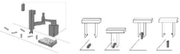
1Paper on “A Pivoting Gripper for Feeding Industrial Parts” by Brian Carlisle, Ken Goldberg, Anil Rao, Jeff Wiegley - In this paper describe a way to orient parts about an arbitrary axis by introducing a rotating bearing between the jaws of a simple gripper. Based on this mechanism, developing a rapidly configurable vision-based system for feeding parts. In this system, a camera determines initial part pose; the robot then reorients the part to achieve a desired final pose.
To automate the assembly of mechanical components, parts must precisely orient prior to packing or insertion. A parts feeder is a machine that orients parts. Currently, the design of parts feeders is a black art that is responsible for up to 30% of the cost and 50% of work cell failures“The real problem is not part transfer but part orientation”.Thus there is a demand for a parts feeder that can be reprogrammed rather than physically modified when geometry changes part.
Figure : The figure shows 4 snapshots progressing from left to right. The gripper grasps the rectangular part along an axis offset from its center of mass, lifts it off the table, and uses the force ofgravity to rotate the part into a standing orientation.
describes the pivoting mechanism in detail and experiments with a vision-based parts feeding system. Last, it discuss the advantages and disadvantages of the proposed system and describes avenues for future research(4).
1. Paper on “Low cost automation using electro pneumatic system an online case study in multistation part transfer drilling and tapping machine”. Submitted at “24th International
Symposium on Automation & Robotics in Construction (ISARC 2007) Construction Automation Group, I.I.T Madras” by M. Muthukkaruppan and K. Manoj.
Fig. Experimental setup of low cost automation This paper discuss the case study and, comparison of productivity of a component using a real time multi stationed Automation Rotary Transfer Line used for Drilling, tapping and inspecting a standard block of size 50*50*75 mm with drill size diameter 5*20 mm long and tapping the drill by M6 machine tap. The clamping of the component, part transfer and feed of the drilling machine spindle is done using electro-pneumatics. The total logic of the system is based on low cost automation with the microcontrollers.(5)
CHAPTER - III
BASIC MECHANISM:-
Definition:-The arrangement or relation of the parts of anything as adapted to produce an effect is called mechanism.
Introduction:-This gives the information about basic mechanism used for actual development of any automatic mechanical system. It includes vary basic but important mechanism; with help of this many different mechanisms can be created. It also explains how this mechanism can work. The various basic mechanisms are as follows:
Kinematic chain(2)
:-
Definition:-When the kinematic pairs are coupled in such a way that the last link is joint to the first link to transmit definite motion then it is called kinematic chain. For example, the crankshaft of an engine forms a kinematics pair with the bearings which are fixed in the pair, the connecting rod with the crank forms a second kinematic pair, the piston with the connecting rod forms a third pair and piston with the cylinder forms a fourth pair. The total combination of these links is a kinematic chain.If each link assumed to form two pairs with two adjacent links, then the relation between the number of pairs(p) forming a kinematic chain and the number of links (l)may be expressed in the form of an equation:
L = 2p – 4
Since in a kinematic chain each link forms a part of two pairs, therefore there will be as many links as the number of pairs.
Another relation between the number of links (l) and the number of joints (j) which constitute a kinematic chain is given by the expression:
J = 3/2 l – 2 Inversions of
mechanism:-When one of the links is fixed in the kinematic chain it is called a mechanisms we can obtained as many mechanisms as the number of links in a kinematic chain it is called the mechanism. So we can obtain as many mechanisms as the number of links in a kinematic chain by fixing, in turn, different links in a kinematic chain. This method of obtaining different mechanism by fixing different links in a kinematic chain is known inversion of mechanism.
Following are the basic mechanisms(2)
:-1.
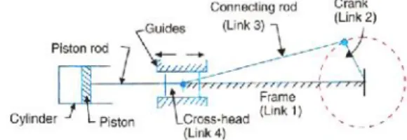
Single slider crankmechanism:-The single slider crank chain is the modification of basic four bar chain. It consists of one sliding pair and three turning pair. It is, usually, found in reciprocating steam engine mechanism. This type of mechanism converts rotary motion into reciprocating motion and vice versa. In a single slider crank chain as shown in the fig. the links 1 and 2, links 2and 3 and links 3and 4 form three turning pairs while the links 4 and 1 form a sliding pair.
Fig. Single slider crank chain
The link 1 corresponds to the frame of the engine, which is fixed. The link 2 corresponds to the crank; describes the pivoting mechanism in detail and
experiments with a vision-based parts feeding system. Last, it discuss the advantages and disadvantages of the proposed system and describes avenues for future research(4).
1. Paper on “Low cost automation using electro pneumatic system an online case study in multistation part transfer drilling and tapping machine”. Submitted at “24th International
Symposium on Automation & Robotics in Construction (ISARC 2007) Construction Automation Group, I.I.T Madras” by M. Muthukkaruppan and K. Manoj.
Fig. Experimental setup of low cost automation This paper discuss the case study and, comparison of productivity of a component using a real time multi stationed Automation Rotary Transfer Line used for Drilling, tapping and inspecting a standard block of size 50*50*75 mm with drill size diameter 5*20 mm long and tapping the drill by M6 machine tap. The clamping of the component, part transfer and feed of the drilling machine spindle is done using electro-pneumatics. The total logic of the system is based on low cost automation with the microcontrollers.(5)
CHAPTER - III
BASIC MECHANISM:-
Definition:-The arrangement or relation of the parts of anything as adapted to produce an effect is called mechanism.
Introduction:-This gives the information about basic mechanism used for actual development of any automatic mechanical system. It includes vary basic but important mechanism; with help of this many different mechanisms can be created. It also explains how this mechanism can work. The various basic mechanisms are as follows:
Kinematic chain(2)
:-
Definition:-When the kinematic pairs are coupled in such a way that the last link is joint to the first link to transmit definite motion then it is called kinematic chain. For example, the crankshaft of an engine forms a kinematics pair with the bearings which are fixed in the pair, the connecting rod with the crank forms a second kinematic pair, the piston with the connecting rod forms a third pair and piston with the cylinder forms a fourth pair. The total combination of these links is a kinematic chain.If each link assumed to form two pairs with two adjacent links, then the relation between the number of pairs(p) forming a kinematic chain and the number of links (l)may be expressed in the form of an equation:
L = 2p – 4
Since in a kinematic chain each link forms a part of two pairs, therefore there will be as many links as the number of pairs.
Another relation between the number of links (l) and the number of joints (j) which constitute a kinematic chain is given by the expression:
J = 3/2 l – 2 Inversions of
mechanism:-When one of the links is fixed in the kinematic chain it is called a mechanisms we can obtained as many mechanisms as the number of links in a kinematic chain it is called the mechanism. So we can obtain as many mechanisms as the number of links in a kinematic chain by fixing, in turn, different links in a kinematic chain. This method of obtaining different mechanism by fixing different links in a kinematic chain is known inversion of mechanism.
Following are the basic mechanisms(2)
:-1.
Single slider crankmechanism:-The single slider crank chain is the modification of basic four bar chain. It consists of one sliding pair and three turning pair. It is, usually, found in reciprocating steam engine mechanism. This type of mechanism converts rotary motion into reciprocating motion and vice versa. In a single slider crank chain as shown in the fig. the links 1 and 2, links 2and 3 and links 3and 4 form three turning pairs while the links 4 and 1 form a sliding pair.
Fig. Single slider crank chain
International Journal of Science Engineering and Advanced Technology, IJSEAT
link 3 corresponds to connecting rod and link 4 corresponds cross head. As the crank rotates, the cross head reciprocates in the guides and thus the piston reciprocates in the cylinder.
2.
Crank slidermechanism:-Common to most reciprocating engines is a linkage known as a crank-slider mechanism. Diagramed in Figure 1, this mechanism is one of several capable of producing the straight-line, backward-and-forward motion known as reciprocating. Fundamentally, the crank-slider converts rotational motion into linear motion, or vice-versa. With a piston as the slider moving inside a fixed cylinder, the mechanism provides the vital capability of a gas engine: the ability to compress and expand a gas. Before delving into this aspect of the engine, however, let us examine the crank-slider
mechanism more closely.
Fig1. Crank Slider Mechanism
It is evident from Figure 2 that, while the crank arm rotates through 180°, the piston moves from the position known as top-center (TC) to the other extreme, called bottom-center (BC). During this period the piston travels a distance, S, called the
stroke, which is twice the length of the crank.For an
angular velocity of the crank (ω) the crank pin A has a tangential velocity component ω S/2. It is evident that, at TC and at BC, the crank pin velocity component in the piston direction, and hence the piston velocity, is zero. At these points, corresponding to crank angle = 0° and 180°, the piston reverses direction. Thus as varies from 0° to 180°, the piston velocity accelerates from 0 to a maximum and then returns to 0. A similar behavior exists between 180° and 360°.The connecting rod is a two-force member; hence it is evident that there are both axial and lateral forces on the piston at crank angles other than 0° and 180°. These lateral forces are, of course, opposed by the cylinder walls. The resulting lateral force component normal to the cylinder wall gives rise to frictional forces between
the pistons rings and cylinder. It is evident that the normal force, and thus the frictional force, alternates from one side of the piston to the other during each cycle. Thus the piston motion presents a challenging lubrication problem for the control and reduction of both wear and energy loss.
The position of the piston with respect to the crank centerline is given by
x = (S/2) cos + Lcos Ø
[ft | m] ……. (1)
where, yA = (S/2) sin = L sinØ can be used to eliminate Ø to obtain
X/L = (S/2L) cos + [1- (S/2L)
sin ] ½ ……. (2)
Thus, while the axial component of the motion of the crank pin is simple harmonic,
XA= (S/2) cos ,
the motion of the piston and piston pin is more complex.
Fig.2 Geometry and notation for the crank slider.
It may be seen from Equation (2), however, that as
S/L becomes small, the piston motion approaches simple harmonic. This becomes physically evident when it is recognized that, in this limit, the connecting rod angle ’Ø‘ approaches 0 and the piston motion approaches the axial motion of the crank pin. Equations (1) and (2) may be used to predict component velocities, accelerations, and forces in the engine. The volume swept by the piston as it passes from TC to BC is called the piston displacement, disp. Engine displacement, DISP,is then the product of the piston displacement and the number of cylinders, DISP = (n)(dips). The piston displacement is the product of the piston cross-sectional area and the stroke. The cylinder inside diameter (and, approximately, also the piston diameter) is called its
3.
Crank and levermechanism:-A part of mechanism of a beam engine which consists of four links, as shown in figure. In this mechanism, when the crank rotates about the fixed center A, the liver oscillates about a fixed center D. The end E of liver CDE is connected to piston rod which reciprocates due to the rotation of cranks. In other words, the purpose of these mechanisms is to convert rotary motion into reciprocating motion.
Fig. Beam engine
4.
Double crankmechanism:-The mechanism of coupling rod of a locomotive which consist of four links as shown in figure. In this mechanism, the links AD and DC (having equal lengths) act as cranks and are connected to the respective wheel. The links CD acts as a coupling rod and the link AB is fixed in order to maintain a constant center to center distance between them. This mechanism is meant for transmitting rotary motion from one wheel to other wheel.
Fig. Coupling rod of a locomotive
Classification of Mechanisms (according to motion)(3)
:-
Introduction:-The various mechanisms have been classified and categorized on the basis of conversion of motion one form to another.
4.1 CONVERSION OF ROTARY MOTION INTO OSCILLATING
MO1TION:-4.2 CONVERSION OF ROTARY MOTION INTO ROTARY
MOTION:-4.4 CONVERSION OF OSCILLATING MOTION INTO REVERSING
MOTION:-4.5 CONVERSION OF ROTARY MOTION INTO RECIPROCATING
MOTION:-4.6 CONVERSION OF RECIPROCATING MOTION INTO ROTARY
MOTION:-4.7 CONVERSION OF ROTARY MOTION INTO LINEAR MOTION
4.8 CONVERSION OF ROTARY MOTION INTO RECTILINEAR
MOTION:-4.9 CONVERSION OF DIFFERENT MOTIONS ACCORDING TO
FEEDING
4.10 DIFFERENTIAL MOTIONS 4.11 SPECIAL MACHANISMS
DETAILS OF MECHANISM(3)
:-
Introduction:-The classified mechanism of previous chapter is to be explaining in detailed as follows:
5.1 CONVERSION OF ROTARY MOTION INTO OSCILLATING
MOTION:-5.1.1 Special cam mechanism (right hand threaded cam for converting rotary into oscillating
motion):-A simple mechanism for converting rotary into oscillating motion consist of a cylinder having a right and left hand thread and half-nut made as shown in fig. This mechanism was incorporated in a specially constructed printing press for the purpose of imparting a reciprocating motion to the rollers which assist in a distributing the ink. A similar arrangement can be used in numerous other applications, when the speed of rotation is not too high and the load is not too great.
Fig. Cylinder Cam C with Right and Left- hand Threads Designed tReverse Direction of Travel of Half-nut B at Each End of Stroke, thus Imparting an Oscillating Motion to Lever A
In the application referred to, three rollers were used for distributing the ink. The two outside rollers were
3.
Crank and levermechanism:-A part of mechanism of a beam engine which consists of four links, as shown in figure. In this mechanism, when the crank rotates about the fixed center A, the liver oscillates about a fixed center D. The end E of liver CDE is connected to piston rod which reciprocates due to the rotation of cranks. In other words, the purpose of these mechanisms is to convert rotary motion into reciprocating motion.
Fig. Beam engine
4.
Double crankmechanism:-The mechanism of coupling rod of a locomotive which consist of four links as shown in figure. In this mechanism, the links AD and DC (having equal lengths) act as cranks and are connected to the respective wheel. The links CD acts as a coupling rod and the link AB is fixed in order to maintain a constant center to center distance between them. This mechanism is meant for transmitting rotary motion from one wheel to other wheel.
Fig. Coupling rod of a locomotive
Classification of Mechanisms (according to motion)(3)
:-
Introduction:-The various mechanisms have been classified and categorized on the basis of conversion of motion one form to another.
4.1 CONVERSION OF ROTARY MOTION INTO OSCILLATING
MO1TION:-4.2 CONVERSION OF ROTARY MOTION INTO ROTARY
MOTION:-4.4 CONVERSION OF OSCILLATING MOTION INTO REVERSING
MOTION:-4.5 CONVERSION OF ROTARY MOTION INTO RECIPROCATING
MOTION:-4.6 CONVERSION OF RECIPROCATING MOTION INTO ROTARY
MOTION:-4.7 CONVERSION OF ROTARY MOTION INTO LINEAR MOTION
4.8 CONVERSION OF ROTARY MOTION INTO RECTILINEAR
MOTION:-4.9 CONVERSION OF DIFFERENT MOTIONS ACCORDING TO
FEEDING
4.10 DIFFERENTIAL MOTIONS 4.11 SPECIAL MACHANISMS
DETAILS OF MECHANISM(3)
:-
Introduction:-The classified mechanism of previous chapter is to be explaining in detailed as follows:
5.1 CONVERSION OF ROTARY MOTION INTO OSCILLATING
MOTION:-5.1.1 Special cam mechanism (right hand threaded cam for converting rotary into oscillating
motion):-A simple mechanism for converting rotary into oscillating motion consist of a cylinder having a right and left hand thread and half-nut made as shown in fig. This mechanism was incorporated in a specially constructed printing press for the purpose of imparting a reciprocating motion to the rollers which assist in a distributing the ink. A similar arrangement can be used in numerous other applications, when the speed of rotation is not too high and the load is not too great.
Fig. Cylinder Cam C with Right and Left- hand Threads Designed tReverse Direction of Travel of Half-nut B at Each End of Stroke, thus Imparting an Oscillating Motion to Lever A
International Journal of Science Engineering and Advanced Technology, IJSEAT
operated by a double rocker arm actuated by the crank arm A, which is fitted with a half-nut B. The right-hand and left-hand threaded C at one end of a rotating shaft serves to oscillates or move the end arm A forward and back. The center link distributing roller is moved by a single rocker arm driven by another threaded cylinder similar to the one shown at C. The rocker arms are pivoted and carry ball-bearing pins that work against the flanges of spools on the ink-distributing rollers. Thus, as rocker arms move back and forth, they transmit the required motions to the ink-distributing rollers.
The half-nut B is made from a T-shape, the thickness of the stem being equal to the width of the thread groove. The stem is formed to a concave shape to feed the counters of the root dia. Of the thread, while its over-all length made somewhat greater than the outside dia. of the thread. Its minimum length must be such as to more than spoon the gap made by the crossing of the right- and left- hand threads. At the center of the T- shaped bar is an elongated hole D, which slides over pin E attached to the crank- arm. Thus, pin E causes the crank to rock back and forth with the longitudinal travel of the nut. An elongated hole is necessary for pin E, since the arm swings in an ark while the nut travels in a straight line.When the half nut approaches the end of its travel in one direction, its axis is on an angle with the center line of the shaft. This angle is equal to the pitch angle of the screw. In order to reverse the travel, the axis of the half-nut must pivot about pin E until it is in the proper angular position for the reverse traverse motion imparted by the thread of the opposite hand lead.The last thread on the cylinder C is cut back a sufficient distance to allow the half- nut to pivot, and the “following” edge where thread ;runs out at the end is filed back sufficiently to allow the nut to clear this surface and the end flange. The nut is also beveled at the edge where it enters the thread. The threaded cylinder C and the half nut B are shown separately in the views to the left.This mechanism operates smoothly, having a short dwell at each end of the stroke while nut reverse and picks up the opposite thread. In the printing press application the two outside rollers are operated by a double rocker arm which causes them to move an equal amount in opposite directions. It is desirable to introduce as much variety as possible into the motion of the three rollers in order to smooth out the ink more effectively. For this reason, the leverage for the crank- arm of the center; roller is made somewhat different from that for the outside rollers. In this case, the length of the thread on the cam for actuating the crank-arm of the center roller is longer than that of the cam for the outside rollers. With this
arrangement, the center roller continuously varies its position in relation to the outer rollers.
5.2 CONVERSION OF ROTARY MOTION INTO ROTARY
MOTION:-5.2.1 Adjustable Dial Type Of Tripping
Mechanism:-The automatic tripping mechanism shown in fig. was designed for drilling machines and may be adjusted to disengage the downward feeding motion of the drill at any depth up to 14 inches. The feeding movement is transmitted through the drill spindle from shaft A, through warm gearing, to shaft B which has a pinion engaging the rack on the spindle quill. The automatic disengagement of the feed is controlled by the engagement of pawl H with liver N. the distance that the spindle feeds downward before the feed is tripped is regulated by graduated adjustable dial I. the graduation on this dial indicate 1/32 inch of the spindle travel, and one complete revolution represents 7 inches of the spindle travel. The pawl H is so designed that it can be set to allow two revolutions of the dial before engaging liver N.The operation of the mechanism is as follows: If the feed is to be tripped automatically in 7 inches or less, pawl H is set as indicated by the dotted lines at K; if it is desired to trip the feed at a distance greater than 7 inches, pawl H is turned to the position shown by the full lines. For example, if it should be required to automatically trip the feed at a depth of 3 inches, the knurled nut L would first be loosened and the graduated dial I turned until the figure 3 on it was opposite the mark on pointer J, after which nut L would be tightened. The pawl H would then be set in the position shown by the dotted lines, with the result that , when the drill had travelled 3 inches, The surface M would come in contact with the side N of the trip arm and disengage the feed. On the other hand, if it were required to drill to a depth of 9 inches before the feed was automatically tripped, the dial I would be set with figure 2 opposite the mark on pointer J, and pawl H would be turned to the position shown by the full lines. With the pawl in this position, the contact of surface O with liver N would not throw out the feed, as the pawl, being loose on its stud, would simply turn and pass the tripping arm without moving it.
Fig. Automatic Feed-tripping Mechanism having Graduated Adjusting Dial for Controlling Times of Disengagement
5.3 CONVERSION OF RECTILINEAR MOTION INTO INTERMITTENT
MOTION:-5.3.1 Overload relief
mechanism:-A release mechanism that was relies for a feed slide subjected to the jamming but that can be also being applied to the various type movements as shown in fig. Oscillating shaft A transmit reciprocating movement to the link B connected to the feed slide through the lever C. it slip feet on the shaft, but it is prevented from turning by a locking arrangement consisting of lever D, locking bar E, locking plate F secured to a projection on a lever C, and spring G. At the outer end of lever D, which is keyed to the shaft, is pivoted to bar E. A tooth in this bar engages a notch in a plate F and is held in this spring G.
Normally, the entire mechanism is locked together and rocks back and forth with this shaft. However if link B becomes overloaded, lever C will stop oscillating and shaft A will merely turn in a hub bore of this lever. Lever D, being keyed to the shaft, will continue to oscillate and cause tooth on bar E to ride out of the notch and slide along the now stationary plate F. the tooth will continue slide back and forth along this plate and in and out of the notch until the overloads on the link B is removed. When this is done, the tooth will engage the notch and the entire mechanism will ones more function as a unit. An electric stud H is a provided so that the angular position of lever C can be adjusted to vary the position of link B at the beginning at end of its stroke.
Fig. Arrangement for Automatically Disengaging a Driving Lever from
it’s Shaft when the Load becomes Excessive
5.4 CONVERSION OF OSCILLATING
MOTION INTO REVERSING
MOTION:-5.4.1 Reversing
mechanism:-In a special electrical switch testing machine an oscillating motion of one shaft is converted to a reversing motion in another shaft, the latter alternating at each reversal between the two speeds of 60 and 30 revolutions per minutes.The shaft X (fig.), on which the segment gear A is keyed, is the oscillating member. The shaft T, to which the irregular motion is transferred, turns in the machine bearing ( not shown ) and serves as a pivot for the arm B. Gears O and P, located under this arm, are keyed on the shafts U and Y and are connected by the three gears S, V and G. the concentric grooves E and D , milled in the segment gear , are joint at both ends to from one continuous groove and serves as a guide for the cam roll C in the end of arm B. dogs R and N, which engage the projection Q on the arm, are fastened securely to the segment gears. Latches J and M swing on shoulder- screws, and normally bear against pins I and K, due to the tension of the coil springs.
Fig. Mechanism for Converting Oscillating Motion into Reversing Motion
In the position shown in the illustration, the segment gear A is oscillating in the direction of the arrow, and the dog R, against lug Q is about to swing the arm B around shaft T. A further upward movement of dog R will throw gear O out of engagement with the segment gear. However, just before the teeth of gear O have become disengaged, a
Fig. Automatic Feed-tripping Mechanism having Graduated Adjusting Dial for Controlling Times of Disengagement
5.3 CONVERSION OF RECTILINEAR MOTION INTO INTERMITTENT
MOTION:-5.3.1 Overload relief
mechanism:-A release mechanism that was relies for a feed slide subjected to the jamming but that can be also being applied to the various type movements as shown in fig. Oscillating shaft A transmit reciprocating movement to the link B connected to the feed slide through the lever C. it slip feet on the shaft, but it is prevented from turning by a locking arrangement consisting of lever D, locking bar E, locking plate F secured to a projection on a lever C, and spring G. At the outer end of lever D, which is keyed to the shaft, is pivoted to bar E. A tooth in this bar engages a notch in a plate F and is held in this spring G.
Normally, the entire mechanism is locked together and rocks back and forth with this shaft. However if link B becomes overloaded, lever C will stop oscillating and shaft A will merely turn in a hub bore of this lever. Lever D, being keyed to the shaft, will continue to oscillate and cause tooth on bar E to ride out of the notch and slide along the now stationary plate F. the tooth will continue slide back and forth along this plate and in and out of the notch until the overloads on the link B is removed. When this is done, the tooth will engage the notch and the entire mechanism will ones more function as a unit. An electric stud H is a provided so that the angular position of lever C can be adjusted to vary the position of link B at the beginning at end of its stroke.
Fig. Arrangement for Automatically Disengaging a Driving Lever from
it’s Shaft when the Load becomes Excessive
5.4 CONVERSION OF OSCILLATING
MOTION INTO REVERSING
MOTION:-5.4.1 Reversing
mechanism:-In a special electrical switch testing machine an oscillating motion of one shaft is converted to a reversing motion in another shaft, the latter alternating at each reversal between the two speeds of 60 and 30 revolutions per minutes.The shaft X (fig.), on which the segment gear A is keyed, is the oscillating member. The shaft T, to which the irregular motion is transferred, turns in the machine bearing ( not shown ) and serves as a pivot for the arm B. Gears O and P, located under this arm, are keyed on the shafts U and Y and are connected by the three gears S, V and G. the concentric grooves E and D , milled in the segment gear , are joint at both ends to from one continuous groove and serves as a guide for the cam roll C in the end of arm B. dogs R and N, which engage the projection Q on the arm, are fastened securely to the segment gears. Latches J and M swing on shoulder- screws, and normally bear against pins I and K, due to the tension of the coil springs.
Fig. Mechanism for Converting Oscillating Motion into Reversing Motion
International Journal of Science Engineering and Advanced Technology, IJSEAT
partial engagement of teeth in gear P and segment A takes place. While gears O and P are being shifted, roller C swings up to the beginning of the groove E. when the roll reaches this position, the oscillating segment A has come to the end of its upward stroke and is about to return. The latch M closes the end grooves and prevents the roll from dropping back to groove D when the segment reverses.The roll now follows groove E and serves to hold gear P in a mesh with segment A until dog N comes in a contact with lug Q. this disengages gear P, after which gear O engaged with segment A again. In the mean time, roll C has force latch J to one side and is swung down to the end of groove D, being prevented from coming out of this groove by the return of latch J. the roll, running in groove D, serves to hold O in a mesh during the return stroke of segment. This complete one cycle of movement.Because of the difference in the number of teeth between gears O and P, as noted in the illustration and the arrangement of gear train, the uniform oscillation of segment A will result in one clockwise revolution of shaft T for every up stroke of the segment, while the down stroke will result in two counter clockwise revolution of the shaft. With some slide modification in the design, shaft T may be made to revolve at varying speed other than described and in the same direction instead of reversing. This may be done by varying the number of teeth in the gears and adding idler between any two of the gears S, V or G.
5.5 CONVERSION OF ROTARY MOTION INTO RECIPROCATING MOTION:-5.5.1 Pumping
Mechanism:-The piston of the pump shown in Fig. has, in addition to rectilinear movement, a rotary motion. This pump was designed for pumping water of other liquids containing foreign materials, such as weeds, pieces of rope, paper, etc, which might enter the pump cylinder. Instead of using suction or discharge valves which would become clogged and cause trouble, the opening and closing of the ports is controlled by the rotary movement of the piston, and any foreign materials of the kinds mentioned are sheared off by the edges of the ports. The rectilinear motion of the piston is obtained from a crank.
Fig. Piston Having Combined Rectilinear and Rotary Movements
A miter gear keyed to the end of the crankpin meshes with a mating gear keyed to the end of the connecting-rod, so that, as the piston is moved in and out, it is also given a rotary motion. The piston is of the trunk type with an opening at both ends and a partition in the center. The head end at the left of the partition contains a port which alternately registers with the suction and delivery ports. When the piston is in the position shown, both ports are closed, but, as soon as the pump rotates in the direction indicated by the arrow, the suction port begins to open. When the crank has moved 90 degrees, the piston port will be exactly over the suction port and, when the opposite dead center is reached, both ports will again be closed. When the crank is on the bottom quarter or at the center of the return stroke, the piston port will be opposite the delivery port.
5.6 CONVERSION OF RECIPROCATING MOTION INTO ROTARY
MOTION:-5.6.1 Feeding mechanism (by air cylinder):-A feeding mechanism operated by an air cylinder was required to convert the constant reciprocating movement of the air piston into an intermittent movement on the outward stroke.
Fig. Mechanism for Converting a Constant Reciprocating Movement
into an Intermittent Movement
This movement was to be at right angles to that of piston. On the return stroke, the motion was to be continues and at a constant speed. The mechanism for obtaining these movements is shown diagrammatically in fig... The reciprocating piston B is attached to the slide A. slide A has a cam groove with the side C formed with a dwell to impart the required intermittent movement to the feeding plunger D on the outward movement of the piston. On the return movement, the side F of the cam groove returns the plunger D to the starting position without the intermittent motion required on the outward movement. There is sufficient friction in the mechanism to keep the roller E of the plunger D in a contact with side C and F on the outward and inward
International Journal of Science Engineering and Advanced Technology, IJSEAT
partial engagement of teeth in gear P and segment A takes place. While gears O and P are being shifted, roller C swings up to the beginning of the groove E. when the roll reaches this position, the oscillating segment A has come to the end of its upward stroke and is about to return. The latch M closes the end grooves and prevents the roll from dropping back to groove D when the segment reverses.The roll now follows groove E and serves to hold gear P in a mesh with segment A until dog N comes in a contact with lug Q. this disengages gear P, after which gear O engaged with segment A again. In the mean time, roll C has force latch J to one side and is swung down to the end of groove D, being prevented from coming out of this groove by the return of latch J. the roll, running in groove D, serves to hold O in a mesh during the return stroke of segment. This complete one cycle of movement.Because of the difference in the number of teeth between gears O and P, as noted in the illustration and the arrangement of gear train, the uniform oscillation of segment A will result in one clockwise revolution of shaft T for every up stroke of the segment, while the down stroke will result in two counter clockwise revolution of the shaft. With some slide modification in the design, shaft T may be made to revolve at varying speed other than described and in the same direction instead of reversing. This may be done by varying the number of teeth in the gears and adding idler between any two of the gears S, V or G.
5.5 CONVERSION OF ROTARY MOTION INTO RECIPROCATING MOTION:-5.5.1 Pumping
Mechanism:-The piston of the pump shown in Fig. has, in addition to rectilinear movement, a rotary motion. This pump was designed for pumping water of other liquids containing foreign materials, such as weeds, pieces of rope, paper, etc, which might enter the pump cylinder. Instead of using suction or discharge valves which would become clogged and cause trouble, the opening and closing of the ports is controlled by the rotary movement of the piston, and any foreign materials of the kinds mentioned are sheared off by the edges of the ports. The rectilinear motion of the piston is obtained from a crank.
Fig. Piston Having Combined Rectilinear and Rotary Movements
A miter gear keyed to the end of the crankpin meshes with a mating gear keyed to the end of the connecting-rod, so that, as the piston is moved in and out, it is also given a rotary motion. The piston is of the trunk type with an opening at both ends and a partition in the center. The head end at the left of the partition contains a port which alternately registers with the suction and delivery ports. When the piston is in the position shown, both ports are closed, but, as soon as the pump rotates in the direction indicated by the arrow, the suction port begins to open. When the crank has moved 90 degrees, the piston port will be exactly over the suction port and, when the opposite dead center is reached, both ports will again be closed. When the crank is on the bottom quarter or at the center of the return stroke, the piston port will be opposite the delivery port.
5.6 CONVERSION OF RECIPROCATING MOTION INTO ROTARY
MOTION:-5.6.1 Feeding mechanism (by air cylinder):-A feeding mechanism operated by an air cylinder was required to convert the constant reciprocating movement of the air piston into an intermittent movement on the outward stroke.
Fig. Mechanism for Converting a Constant Reciprocating Movement
into an Intermittent Movement