A Novel Approach of FPGA Implementation of Transceiver
System
P.Lokaranjan rao 1 , K.Supreem Babu2
Assistant professor, Department of Electronics and Communication Engineering, CITM, Kothavalasa, INDIA 1 Assistant professor, Department of Electronics and Communication Engineering, CITM, Kothavalasa, INDIA 2
1 [email protected] 2 [email protected]
This work given a innovative model to design an efficient wireless system which helps to integrate this with other technologies at a low cost. The system read analogue information by a biomedical sensor which is attached to the patient. The recorded data are converted digitally using analogue-to-digital converter and sent to transmitter through field programmable gate arrays (FPGAs). VHDL has been used to implement the required functions of the FPGA, such as bus interfacing, data buffering, compression and data framing. The compression of data is done with RLE and it is so efficient. On the other hand, Simulink software has been used to model and simulate FPGA transmitter/receiver. The overall performance of the system has been verified by a well developed simulation model.
Key words: RLE, SPI, HDLC, FPGA
1.INTRODUCTION
Equipment is long battery life, lightweight and small Home healthcare costs have increased by 400% in the last five years. Although hospital or nursing home care can be delivered at the patient’s home, professional services such as clinical and medication monitoring are still required. On the other hand, advancement in wireless and Internet technologies are developing rapidly and has opened new opportunities for the health services to reconsider the traditional model of patient care [1]. In the next 25 years, the global population over the age 65 would increase by88% The challenge is to raise or at least maintain the present level of healthcare provision without ending up in an uncontrolled cost explosion. The increasing number of researchers and manufacturers who are working towards a new generation of wireless technology applications in the field of medicine has led to an improvement in the quality of patient care and also reduction in cost . One of the areas in healthcare that best lend itself to wireless
technology is patient monitoring, also known as wireless telemetry. By attaching a wireless monitoring device to the patient’s bedside or directly to the patient, physicians can monitor vital signs from down the hall to across the town. The most critical features of wearable health monitoring dimensions [2]. Continuous monitoring during normal activity also requires that the device can be hidden to protect user’s privacy. In order to make the monitoring devices easily wearable and suitable for the patient, they need to be designed ergonomically. The equipment must also produce high-quality signals, be easy to wear and remove, robust and suitable for different environments and users, both males and female. The aim of this work is to present a useful model that .combines both hardware and software environments and achieves the described demands. The key features of the introduced models are low complexity, low power consumption and efficient data transmission. The main motive behind using a field programmable gate array (FPGA) device to implement the digital part of the model is to have a ready platform for ASIC, which is the next stage of this research work. In addition, FPGA design is characterized to be configurable and can be upgraded any time, which is an attractive feature that cannot be obtained with any other fixed hardware microprocessors or digital signal processing (DSP) devices.
2. SYSTEM SPECIFICATIONS
second FPGA is interfaced to the output of the receiver and is responsible for processing the data inversely like de-framing and de-compressing.
Fig: 1 Block Diagram of system
3. FPGA Description
The units and the flow of data through the system are controlled by a main finite-state machine (FSM) controller. At the receiver end, the system units of the FPGA are organized as shown in Fig. 3. The data recovery main blocks of the transmitter side FPGA are known in Fig. 2. The different units of the system were coded using VHDL simulated with ModelSim SE V6.0a and implemented using ISE7.1. The final implementation was done using Spartan-3 device, as it provides the various features that solve designer’s challenge throughout the entire system. From Fig. 2, the FPGA consists of mainly a adc scanner, buffer, run length encoding (RLE) compressor and high data link control (HDLC) units. The operation of the system unit is needed to extract the clock from the received bit stream. The HDLC framer and the RLE de-compressor blocks are designed to reconstruct the original data bytes sent by the transmitter.
ADC
RLE Compressor HDLC Framer Modulator
BUFFER Sensor1
If FIFOEna= Sensor 31
Fig 2 Building blocks of the transmitter FPGA
DAC
RLEDE Compressor HDLC DeFramer DeModulator
BUFFER Sensor1 Sensor31
Fig 3. Building blocks of the receiver FPGA
4. RLE compressor
Data compression is effective when the measured signals are expected to be slow and repeatable. The task of this unit is crucial to the system power performance. RLE is a conceptually simple form of compression. RLE consists of the process of searching for repeated runs of a single symbol in an input stream, and replacing them by a single instance of the symbol and a run count. A simple flowchart of the RLE implementation is shown in Fig. 4.
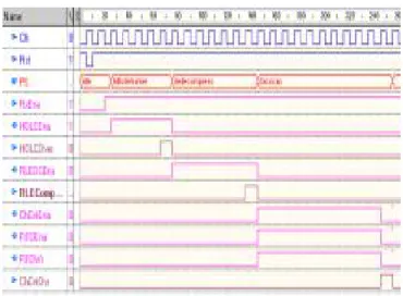
A sample of the output simulation waveforms is shown in Fig. 5, where the three waveforms marked are the input data bytes, valid data signal which is active (high) when there is a new or not repeated data and the two bytes (input and count) output data. The HDL code for the compressor has been written as a state machine and optimized to only two states. The code also has been synthesized successfully to achieve good device utilization. It is worth to mention that other types of compression techniques have been considered in this work, but it was found that RLE is more suitable in terms of design complexity, power resources and compression performance.
5. RLE de-compressor
To reconstruct back the compressed data bytes, a RLE de-compressor is introduced at the receiver side FPGA. Again a simple algorithm has been adopted to implement the block tasks as shown in Fig. 6.
After initialization, the de-compressor is set in a standby mode for the embedded buffer in the de-framer to be filled. Two bytes, information and count bytes are loaded into special 16-bit register each time. The count byte determines the number of times the information byte needs to be sent to the next stage, a sample of the output waveforms obtained from running the test bench is shown and both compressed and uncompressed output data bytes have been identified.
6. HDLC framer
This unit is considered to be the main core of the system model, where the data are grouped into frames and sent to the transmitter. HDLC protocol is a bit-oriented protocol that is used as a data link for most of the current communication systems [5]. The main features provided by this protocol are:
1. Synchronous operation;
2. Start and end of frame pattern generation;
3. Zero insertion and removal for transparent transmission;
and
4. Cyclic redundancy check (CRC) generation for error Handling.
6.1 HDLC frame
The basic structure of the HDLC frame is shown in Fig. 7.
1. Start and end flags, represented by the sequence (01111110), are required for synchronous transmission. 2. Address field is used to identify the destination address at
the receiver side.
3. Control field is used to classify the HDLC frames according to the link configuration type. 4. Information field contains the transported data. 5. Frame check sum (FCS) is used to detect errors by adopting CRC generation.
7. System implementation
Recently, number of models for the HDLC protocol has been developed [6–8]. The main blocks of HDLC transmitter are shown in Fig. 8. An FSM is responsible for generating all the necessary internal control signals
required by the different modules. First, the controller checks if there is a valid data output from the compressor and then starts loading the bytes into FIFO memory storage. Then the data are read serially from the memory storage and sent to the CRC module to generate the frame check sequence (FCS). The bit stuffer is responsible for examining the frame content and checking every five consecutive 1s bits including FCS bits. If five consecutive 1s are detected, a 0-bit is inserted into the serial bit stream. This helps the receiver to distinguish the actual data transmitted. The start and end flags are generated at the final stage and attached to the frame. Also, the transmitter fills the gaps between the frames when the transmission is idle by sending a sequence of eight consecutive 1s. The received frames are processed inversely by similar structure at the receiver control to recover the transmitted bytes. All the modules of both HDLC transmitter and receiver have been modeled, simulated and synthesized successfully.
8. Simulation Results
iii)Compressor
Fig. 4 RLE compressor implementation
iv) HDLC Framer
Fig. 7 Main fields of the HDLC frame structure
9. Conclusions
In this paper, a mixed hardware and software simulation environments have been used to model a remote short-range wireless system. Although HDL provides many high-level abstractions and language constructions for behavioural modelling, its synthesizable subset is far too restrictive for system-level design. On the other hand, Simulink environment provides a powerful high-level mathematical modeling environment for digital communication systems that can be widely used for algorithm development and verification. The two main operations implemented by the transmitter FPGA are compression and framing. RLE has been used to compress the stored data bytes efficiently with an optimal number of states. The HDLC protocol has been used successfully for framing the data and providing error-handling mechanism to the receiver. All the FPGA modules have been verified and implemented using Xilinx Spartan-3 device. During the development of the VHDL codes, our main goal was to make all the units synthesisable. A detailed description about both transmitter and receiver units was given. The transceiver system performance was tested under different conditions. The implemented model showed a good capability in recovering the original data at the receiver side with different transmission frequencies. The simulation running time is considered to be the main limitation of using Simulink. Real-time simulation of both the Simulink and the VHDL models is not the motive of this work, but to build a realistic design suitable for future hardware design. The VHDL code execution has been optimized using the code coverage feature of the ModelSim. Such feature can identify the unused ‘dead’ code that has a high impact on the simulation acceleration time and reducing both waste as well as risk in the targeted design. The design has a feasibility that programming of number of channels.
References
[1] Folke, M., Andreasson, J., Hok, B., Linden, M., Nilsson, G., Ekstrom,M., and Backlund, Y.: ‘Artefact reduction in lemetric ECG monitoring’. Proc. 12th Nordic Baltic Conf. on Biomedical Engineering and Medical Physics, Island, June 2002, vol. 2, pp. 18–22
[2] Guillen, J.M., Millet, J., and Cebrian, A.: ‘Design of a prototype for dynamic electrocardiography monitoring using GSM technology’. Proc. IEEE/EMBS 23rd Annual Int. Conf., Turkey, October 2001, vol. 4, pp. 3956–3959
[4] Andreasson, J., Ekstrom, M., Fard, A., Castano, J.G., and Johnson, T.: ‘Remote system for patient monitoring using Bluetooth/spi trade’. IEEE Sensors Proc., June 2002, vol. 1, pp. 304–307
[5] Razavi, B.: ‘RF microelectronics’ (Prentice-Hall, NJ, USA, 1998)
[6] Michael, R., and Patel, A.: ‘Performance analysis of an HDLC based protocol with data compression’, Comput. Commun. J., 1997, 20, (7), pp. 567–575.
[7] Yuanlin, L., Zhigong, W., Lufeng, Q., and Bin, H.: ‘Communications. Design and implementation of multi-channel high speed HDLC data processor’. Proc. IEEE Circuits and Systems and West Sino Expositions, China, June–July 2002, vol. 2, pp. 1471–1475