An Electrical Model to Design a Metamaterial Left
Hand Antenna
Abdelhak Ferchichi, Sabri Beldi and Ali Gharsallah
Technology Unit of research Circuits and Electronics Systems High Frequency Faculty of Science, University El Manar, Tunis, Tunisia
[email protected], [email protected], [email protected]
Abstract:This paper proposes a novel approach to study the Left hand antenna using an adequate electrical model. The structure is composed by a periodic Split Ring Resonator and a metallic wires, that’s why the proposed model take into consideration the model of each element and the coupling between the element. Due to the complexity of the structure, the model becomes very important because it’s simple, accurate and a very fast. Besides, once the model is built, it will be easy to control the structure with any change in the structure, the excitation, the substrate. The proposed antenna was manufactured on a FR-4 epoxy. The antenna is designed to RFID application, exactly for an RFID Reader. The antenna presents a significant gain superior to 16dB, and it is designed to simulate at 2.45 GHz.
Keywords: Split Ring Resonator SRR, RFID TAG, RFID
Reader, Parasitic Antenna, Lumped element, left hand.
1.
Introduction
Metamaterial, also known "Left-handed materials," are a structuring metallo-periodic. Those materials have an artificial electromagnetic properties not present common in nature: a permittivity and a permeability both negative,[1-6]. Those structures are constructed by periodically arranging unit cells, such as split-ring resonators (SRRs) and thin wires. Due to the resonant nature of the cells, electromagnetic properties of the host medium, i.e., permittivity, permeability, or both, can effectively become negative for some frequencies. Although metamaterial were theoretically studied more than 40 years ago their actual realizations were achieved recently. Besides, many studies are based in how to enhance the electromagnetic property of the metamaterial and to improve the use of those structures. Since then, the Metamaterial have continued to attract the interest of researchers because they allow considering new applications in the field of microwave. Due to these efforts, metamaterial have been utilized in various applications such as sub-wavelength focusing, cloaking, and designed improved antennas. Recently, antenna and its feed system in wireless communications require to be multifunctional for enhancing flexibility and feasibility, such as easy of integrate, low-profile, inexpensive and ease of fabrication, and wideband or multiband operating. For this reason, left hand metamaterial were presented for enhancing antenna design and proposed a miniaturized antenna or an antenna with high gain or high directivity, [7-11]. Recently, one of the main applications is the radio frequency identification RFID where many works
are developed to propose novel design for both components of this system: TAG and Reader, [12].
Many works are developed to study left hand antenna, first we can mention Otto. Set all, introduce a λ-resonator ring antenna with a Composite right/left-handed CRLH metamaterial as which resonate with a dual frequency, [13]. Second, Yu, A et all present circularly polarized ring antenna by using CRLH metamaterial, [14]. Thirdly, Yang R et all in [15] discuss a metamaterial bilayered substrate to verify the wavelength aspect in a microstrip antenna, in [16], Yan. R et all develop some microstrip antenna using left hand metamaterial. Fourthly, Wu, B et all in [17] enhance the gain of antenna by introducing metamaterial aspect. Finally, Vardaxoglou, Y. and F. Capolino in [18] enhance the directivity by using metasurface and metamaterial.
In our work, we have thinker about using the property of the left hand structure near to a simple patch antenna in order to propose a novel antenna with a high gain. The major problem was how to determine exactly the geometry of the antenna and how to control the hole of structure. That’s why; we have tested the tools of electrical model to modelize the left hand antenna. The proposed model is a simple, accurate and a fast tool. Besides, with this technique we can modelize all the proposed structure which can be very useful to introduce it then in a real application. In our case, the goal is to propose antenna for an RFID reader. The principal parameters in our design are to improve the gain and to have a resonant frequency equal to 2.45GHz.
Mainly, we propose in our paper the possibility of using Left hand metamaterial antenna for RFID application which helps us to improve the gain of the antenna which increases the readable range of RFID reader. Besides, one of the important advantages of our contribution is the use of electrical model which decrease simulation times from hours to a few seconds and also this tools give us the possibility to control easily all antenna parameter.
2.
The Left Hand Cellule
2.1 The Geometry of the elementary cellule
The structure is composed by two different entities: a rectangular split ring resonator SRR and two micro strip lines.
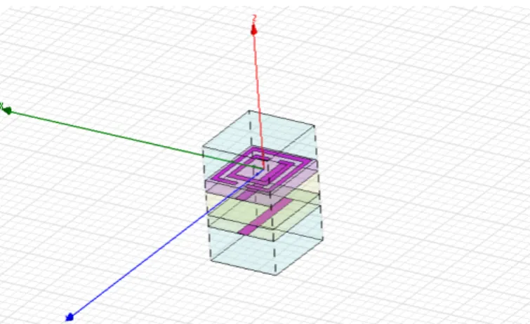
With the SRR we can obtain a negative permeability and a negative permittivity with the two lines so we can offer a Left/Hand structure. The proposed design is simulated using HFSS, figure 1.
Figure 1. The geometry of the proposed Square SRR antenna
In the next section, we will verify the effective aspect of both permeability and permittivity.
2.2 Negative permeability
The SRR was introduced in the first time by Jhon Pendry in 1999, [19], to produce material with negative permeability. There are essentially two types of SRR: circular and square. In the last few years, many works present this kind of antenna as the best solution for RFID systems, [20, 22]. This is because of the SRR propriety and its miniaturized dimensions.
By applying the inversion method, we can calculate the permeability from the transmission and reflection coefficients.
Both coefficients are obtained from numerical simulations in software HFSS. This inversion method can also be applied to experimental characterization of metamaterials where the different coefficients of the matrix S are known.
Coefficients of transmission and reflection waves Electromagnetic (EM) through a homogeneous material of thickness d are given in terms of refractive index n and impedance Z of the material, by the following relationships.
*
(1)
n Z
µ
=
(
)
(
)
2 2
2 2
1
(2)
1
r
t
Z
r
t
+
−
= ±
−
−
' "
(3)
n
= +
n
in
( )
( )
'
Im
arctan
Re
(4)
Y
m
Y
n
kh
π
±
=
(
)
(
)
(
)
2
2 2
2 2 2 2
1 (5)
1
X= 1 11 21 (6)
2S21
1 1
Y= 1 11 21 1 1 11 21 (7)
2S21 2S21
Y X X
S S
S S S S
= ± −
− +
− + ± − − +
From the simulation results obtained by using HFSS and after applying the equation above, we can obtain the variation of permeability in the range of studied frequencies, figure 2.
Figure 2. The permeability of the SRR cellule
a. S12 b. S11 c. the permeability
As can be seen in the previous figure, the SRR present a negative permeability from 2.43 GHz to 2.62 GHZ.
2.3 Negative permittivity
The Design of an effective structure with a negative effective permittivity was largely inspired by the plasma physics. Pendry's team showed that the electromagnetic response of a periodic array of parallel metal rods of very small radii is similar to that of a plasma low density charged by heavy particles.
effective permittivity is negative for frequencies below the plasma frequency. Electromagnetic properties of these parallel rods inspire many interests today for the implementation of composite materials with simultaneously negative permittivity and permeability [23-24].
The plasma frequency can be calculated using the many equations. For our case, we have used the equation given by Maslovski in [25] :
(
)
0 2
(8)
2
ln
4
p
c
f
a
a
r a
r
π
=
−
‘r’ is the radius of the metal lines, and ‘a’ is the distance between the two micro strip lines.
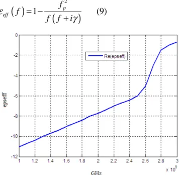
The permittivity is calculated by using the equation bellow and then presented in the figure 3.
( )
1
(
p2)
(9)
eff
f
f
f
f
i
ε
γ
= −
+
Figure 3. The permittivity of the two microstrip lines
As can be seen in the figure 3, the permittivity still negative in all the frequency range, from 1GHz to 3 GHz.
Thus, the proposed elementary cellule (the SRR and the two micro strip lines) present an effective permeability and permittivity witch verify the Left/Hand aspect of our structure.
2.4 The proposed electrical model for the Left/Hand cellule
HFSS like other software (ADS, IE3D, CST…) resolve the electromagnetic equation (in their integral or differential form) in order to give the simulation results. But those techniques cannot be considered always as the best solution for many reasons. First, we cannot take the calculation of all kinds of losses. Secondly, it will be very difficult to control antenna parameters like return loss, input impedance in case of modifying characteristics of antenna (substrate, geometry, and excitation).
Besides, the simulation of complex antenna takes a lot of time. That’s why, using the electrical model as a tools of simulation will be very interesting. For our Left/hand structure, the problem is the absence of analytic equation to control the parameters antenna from the geometry. So building an electrical model will be benefic for our study. In building the Left/Hand model, we followed those steps:
• The SRR model: each ring is replaced by its equivalent model. Two possible configurations can be used to build the SRR electrical model: parallel or serial configuration. We have adopted the serial configuration because it will be easy to introduce with other model. In our contribution the ring is replaced by three lumped elements: a resistance, a capacitor and an inductance. Those parameters are calculated by using the equation developed in our previous works, [26], figure 4.
Figure 4. The electrical model of the SRR cellule
• The two micro strip lines are replacing by an RLC bloc, one line is considered as an effective ground plane for the second. In our frequency range, the parameter for this model is limited to a resistance (modeling losses) and a capacitance (modeling the resonance cavity). We calculated th two lumped element with the equation developed in our preceding works, [27], figure (5).
Figure 5. The electrical model of the two microstrip lines
Figure 6. The electrical model of the Left/Hand cellule
3.
The proposed RFID Left/Hand Antenna
3.1. RFID Reader Antenna
The RFID system is composed by a TAG and a reader which is responsible for several tasks in communication in identification systems. Indeed, it must first enable the TAG , then it must structure the signal sequence contacted TAG and finally , it transfers the data to the TAG application software. For the first two tasks, the reader TAG provides the energy needed for communication TAG - Reader. At this stage, it is important to introduce the notions of power where the antenna parameters directly affect the system performance. In fact, every antenna is characterized by a density of radiation that can be calculated in the case of an isotropic antenna by equation:
2
(10)
4
EIRP
P
S
R
π
=
Where
P
EIRP the effective isotropic radiation power and R is is the Readble range which is the distance between the reader and the TAG. This distance is calculated by using the equation bellow:2 2
0 4 1.
3
.
(11)
4
reader T
P G
G
R
P
λ
π
=
As can be seen, we can increase the readable range by proposing an antenna with high gain on tag or on reader. Thus, because of size reduced of tag antenna, it will be more easily to propose a reader antenna with high gain. For this reason, we propose to use the metamaterial to propose a very high gain antenna for RFID reader.
3.2 The proposed Design
The analysis of metamaterial Left Hand Section is very useful for the rest of this paper. Indeed, this type of metamaterial with a permittivity and negative permeability simultaneously will be used in the immediate vicinity of an antenna in order to study its influence on the radiated energy. The antenna we use is a rectangular patch antenna. As a first step, a study of the antenna alone is done. Modeling of the antenna depends
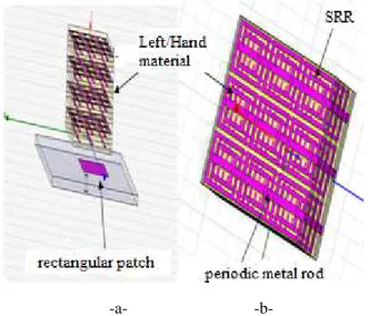
on the homogenized metamaterial Left Hand in terms of resonance frequency. In fact, the antenna must have an operating frequency in the same band where the permittivity and the permeability are negative, figure 7.
Figure 7. The proposed Left/Hand Antenna
a. The metamaterial antenna b. The Left/Hand structure
3.2 The electrical model of the new antenna
The problem with this structure is that it is very complex. That ‘why there is no analytical equations to control the resonant frequency of the proposed antenna. In addition, the complexity of this structure makes a very high simulation time up to several hours.
In this case, the electrical modeling tool will be most useful because it allows us to control the resonance frequency as a function of different geometrical parameters of the structure left hand. In addition, once the model is built, the simulation lasts only seconds.
We begin by building the electrical model of the left hand zone, and then the electrical model of a coaxial cable excited patch and finally incorporate a capacity that represents the coupling between the patch and the network of rods and SRR. All the parameters models are calculated by the equation developed previously.
4.
Simulation Results
Many techniques are used for the design of metamaterial antenna. These techniques use numerical methods based on solving electromagnetic equations in their integral or differential form. As HFSS is one of the most software used to design left/Hand antenna, we used it for simulation of our proposed reader antenna. This simulator provides full his results by solving electromagnetic equations in differential forms. But HFSS present some limitation in our case such:
• we cannot make the calculation of all kinds of losses
• We don’t have the ability to control the antenna parameters such as return loss, input impedance when we change geometry of the antenna, the nature of substrate.
• A very long time for simulation
Therefore, the equivalent circuit is very useful for the parametric analysis of our proposed antenna. In our case we replaced our Left/Hand antenna by an equivalent circuit based on the model of Left/Hand cellule proposed in the second section.
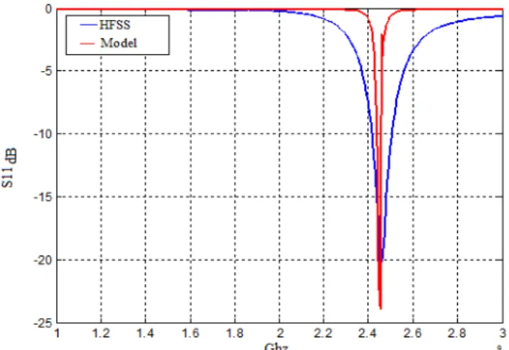
Thus, we can verify that our antenna has good resonance frequency of about 2.45 GHz. Thus, we can see that we could achieve a high gain antenna, which will be very useful in many applications such as RFID Reader. It may be noted that the model has the same resonance frequency that was obtained by HFSS. The difference in bandwidth is due to the difference between the losses calculated in HFSS and the loss calculated by the electrical modeling, figure 8.
Figure 8. Return Loss of the Left/Hand Antennaand the
electrical Model
Besides of the comparaison of return loss between the result obtained by using HFSS and electrical model, we note also that the simulation time is very different between the two techniques. Indeed, the simulation time bu using HFSS is more than 10 hours but by using the electrical model is about 7 seconds.
Finally, when we looking on the radiation pattern of the proposed antenna, we can say that it presents a high gain, which is value of about 16.22 dB, figure 9.
Figure 9. The radiation pattern of the proposed antenna
5.
Conclusions
High gain and high efficiency Left/Hand antenna operating at 2.45 GHz have been developed in this paper. This antenna is simulated using HFSS. It present a high gain with more than 16.22dB.The proposed antenna was analyzed with electrical model tools. The proposed model gives good advantages such as much reduced simulation time and the possibility to control the return losses very easily when we change the geometry, the substrate and the excitation of the Left/Hand antenna.
References
[1] G. V. Eleftheriades and K. G. Balmain, Eds., Negative-Refraction Metamaterials: Fundamental Principles and Applications. Hoboken-Piscataway, NJ: Wiley-IEEE Press, 2005.
[2] R. Marqués, F. Martín, and M. Sorolla, Metamaterials With Negative Parameters: Theory, Design andMicrowave Applications. Hoboken, NJ: Wiley, 2008.
[3] Nasimuddin , Zhi Ning Chen ; Xianming Qing , “Handed Leaky-Wave Antenna With Consistent Gain”, ”, IEEE Transaction antenna and propagation, Vol 60, Issue 11, pp.5056-5062, November 2012
[4] Nasimuddin , Zhi Ning Chen ; Xianming Qing, “Substrate Integrated Metamaterial-Based Leaky-Wave Antenna With Improved Boresight Radiation Bandwidth”, IEEE Transaction antenna and propagation, Vol 61, Issue 7, pp.3451-3457, July 2013 [5] Y. D. Dong and T. Itoh "Composite right/left-handed
substrate integratedwaveguide and half mode substrate integrated waveguide leaky-wave structures", IEEE Trans. Antennas Propag., vol. 59, no. 3, pp.767 -775 2011
.
[6] T. Kodera and C. Caloz, “Uniform ferrite-loaded open waveguide structure with CRLH response and its application to a novel backfire- to-endfire leaky-wave antenna,” IEEE Trans. Microwave Theory Tech., vol. 57, no. 4, pp. 784–795, Apr. 2009.
[7] H.-X. Xu, G.-M. Wang, and J.-G. Liang, “Novel CRLH TL metamaterial and compact microstrip branch-lin coupler application,” Prog. Electromagn. Res. C, vol. 20, pp. 173–186, 2011.
[8] T. Iwasaki, H. Kamoda, T. Derham, and T. Kuki, “A composite right/left-handed rectangular waveguide with tilted corrugations for millimeter-wave frequency scanning antenna,” in Proc. 38th Eur. Microwave Conf., Amsterdam, The Netherlands, pp. 563–566, Oct. 2008. [9] H.-X. Xu, G.-M. Wang, and J.-Q. Gong, “Compact
dual-band zerothorder resonance antenna based on CRLH TL using fractal-shaped complementary single split ring resonator pair,” Chinese Phys. Lett., vol. 29, no. 1, p. 014101, 2012.
[11] M. Navarro-Tapia, “Analysis and design of slot array antennas on composite right/left-handed waveguides,” Ph.D. dissertation, Dept. Ingeniería de Comunicaciones, Universidad de Málaga, Málaga, Spain, 2011.
[12] A.Ferchichi, F. Najib, A.Gharsallah, “A Sierpenski Slot Antenna as a TAG RFID Antenna”, International Journal of Communication Networks and Information Security IJCNIS, Vol 2, No 3, pp. 248-252, December 2010.
[13] Otto, S. Rennings, A. Caloz, C. Waldow, P. Itoh, T, “Composite Right/Left-Handed Lambda-Resonator Ring Antenna for Dual-Frequency Operation”, IEEE Antenna and propagation society international symposium, 2005, VOL 1A, pp 684-687.
[14] Yu, A., F. Yang, and A. Elsherbeni, \A dual band circularly polarized ring antenna based on composite right and left handed metamaterials," Progress In Electromagnetics Research, Vol. 78, pp 73-81, 2008. [15] Yang, R.; Xie, Y.; Li, D.; Zhang, J.; Jiang, J.,
“Bandwidth Enhancement of Microstrip Antennas with Metamaterial Bilayered Substrates”, Journal of Electromagnetic Waves and Applications, Vol 21, No 15, 2007 , pp. 2321-2330
[16] Yang, R., Y. Xie, P. Wang, and L. Li, "Microstrip antennas with left-handed materials substrates," Journal of Electromagnetic Waves and Applications, Vol. 20, No. 9, 1943-1953, 2006.
[17] B.-I. Wu, W. Wang, J. Pacheco, X. Chen, T. Grzegorczyk and J. A. Kong, “A STUDY OF USING METAMATERIALS AS ANTENNA SUBSTRATE TO ENHANCE GAIN”, Progress In Electromagnetics Research, PIER 51, 295–328, 2005
[18] Vardaxoglou, Y. and F. Capolino, Review of highly-directive flat-plate antenna technology with metasurfaces and metamaterials,IEEE Proceedings of the 36th European Microwave Conference, 963-966, Sept. 2006.
[19] J. B. Pendry, A. J. Holden, D. J. Robbins, and W. J. Stewart, “Magnetism from conductors and enhanced nonlinear phenomena”, IEEE Transactions on Microwave Theory and Techniques, vol.47, no. 11, pp. 2075–2084, November 1999
[20] Paredes, F. Gonzalez, G.Z. Bonache, J. Martin, F. “ Dual-Band Impedance-Matching Networks Based on Split-Ring Resonators for Applications in RF Identification (RFID )”, IEEE Transactions on Microwave Theory and Techniques, vol 58, no 5, pp. 1159-1166, 2010.
[21] Benjamin D. Braaten, Robert P. Scheeler, Michael Reich, Robert M. Nelson, Cherish Bauer-Reich, Jacob Glower1 and Gregory J. Owen1 “Compact Metamaterial –Based UHF RFID Antennas: Deformed Omega and Split-Ring Resonator Structures”, ACES Journal, vol 25, no. 6, pp. 530-542, Juin 2010.
[22] Benjamin D. Braaten , “ A Novel Compact UHF RFID Tag Antenna with Series Connected Open Complementary Spit Ring Resonator (OCSRR) Particles”, IEEE Transaction on Antennas and Propagation, vol 58, no 11, pp. 3728-3733, Août 2010 [23] J. B. Pendry, A. J. Holden, D. J. Robbins, and W. J.
Stewart, “Low frequency plasmons in thin wire
structures”, Journal of Physics : Condensed Matter, , no. 10, pp. 4785–4809, March 1998.
[24] P. Gay-Balmaz, C. Maccio, and O. J. F. Martin, “Microwire arrays with plasmonic response at microwave frequencies”, Applied Physics Letters, vol. 81, no. 15, pp. 2896–2898, October 2002.
[25] S. I. Maslovski, S. A. Tretyakov, and P. A. Belov, “Wire media with negative effective permittivity : A quasi-static model”, Microwave and Optical Technology Letters, vol. 35, no. 1, pp. 47–51, October 2002. [26] Ferchichi. A, A. gharssalah “A Discution of a SRR
Parasitic Antenna for an RFID TAG ANTENNA by Using Lumped Elements”, EUCAP 2012, pp 3181-3185 March 2012, republic tcheq,