AUSTRALIAN JOURNAL OF BASIC AND
APPLIED SCIENCES
ISSN:1991-8178 EISSN: 2309-8414 Journal home page: www.ajbasweb.com
Open Access Journal
Published BY AENSI Publication
© 2016 AENSI Publisher All rights reserved
This work is licensed under the Creative Commons Attribution International License (CC BY). http://creativecommons.org/licenses/by/4.0/
To Cite This Article: S. Raahul Sankar, L. Yuvaraj and Dr. D. Selvaraj., Wireless Surveillance Robot Using Dtmf Technique. Aust. J.
Basic & Appl. Sci., 10(1): 227-231, 2016
Wireless Surveillance Robot Using Dtmf Technique
1
S. Raahul Sankar, 2L. Yuvaraj and 3Dr. D. Selvaraj
1Department of ECE Panimalar Engineering College 2Department of ECE Panimalar Engineering College
3Associate Professor, ECE Panimalar Engineering College
Address For Correspondence:
S. Raahul Sankar, Department of ECE Panimalar Engineering College. E-mail: [email protected]
A R T I C L E I N F O A B S T R A C T
Article history:
Received 10 December 2015 Accepted 28 January 2016 Available online 10 February 2016
Keywords:
Our project aims to present a microcontroller based surveillance platform that is effective as a surveillance tool in both high and low visibility condition with multiple sensors like PIR sensor, temperature sensor, ultrasonic sensor, LDR and light source.It can be implemented by using a smart phone operated robotic system which gives live video feedback that directly stores in cloud using cloud computing technique. The 3G network for video transmission is provided by the smart phone attached with robot.DLINK software is used while setting password. The recording of video is done through IP camera and it can be viewed either through user cell phone using DLINK application or through internet using DLINK website. Cloud computing relies on sharing of resources to achieve coherence and economies of scale, similar to utility. The communication is secure as we can use data encryption and DTMF decoder table.MT8870 a modern and efficient DTMF decoder is used which reduces the noise passes and makes the whole system efficient. The circuit is less complex cost effective, at the same time it has higher efficiency and smarter technology.
INTRODUCTION
Surveillance is the monitoring of behavior, activities or other changing information, usually of people .This can include observation from a distance by means of electronic equipment and it can include simple, relatively low-technology methods such as human intelligence agents. Surveillance is used by governments for intelligence gathering, prevention of crime, the protection of a process and as well as in military sector since it helps in increasing security of the society, hence minimizing terrorist and criminal activities. In the proposed system, robotic movement is controlled by DTMF tones. It uses the internet to transfer the data between robot and user. The smart phone is used to give the control commands to the robot for its movement, and receive the video frames of the surrounding environment from the camera mounted in the robot. Since the mobile is used the user need not be present nearby. He can present anywhere where network is available.3G network must be available for proper video transmission without any time delay resulting in data dropout. Temperature sensor and PIR sensor with FRESNAL lens are used to measure temperature and detect presence of human respectively.
keypads are laid out on a 4x4 matrix. It is the combination of two sine wave tones to represent a key. These tones are called row and column frequencies as they correspond to the layout of a telephone keypad. Row frequencies are lower group of frequencies whereas column frequencies are of higher group of frequencies. When the call is on, the pressing of any numerical key leads to generation of DTMF signal which is audible on the other side. Thus each key has unique frequency pair and thus unique DTMF tone. For example, DTMF tone for key 6 is sum of two sinusoidal waves of frequency 1477 Hz and 770 Hz.There are 12 standard signals and 4 extra buttons A, B, C, D.
Fig. 1: Block diagram for frequencies of DTMF signal.
Fig. 2: DTMF waveform generation.
Overall System:
The overall system is splitted into three sections called robotic movement section, video transferring section and sensor section. In video transferring section, cloud computing technique is used. Cloud computing is a recently evolved computing terminology or metaphor based on utility and consumption of computing resources. It involves deploying groups of remote servers and software networked that allow centralized data storage and online access to computer services or resources. Among the two methods available for cloud computing namely public and private, we use a private or hybrid type of cloud computing. Cloud computing provides advantages such as
• Agility-lightness, speed • Cost reductions • Vast storage medium
• Device and location independence • Easy maintenance
• Multitenancy- friendly resource sharing
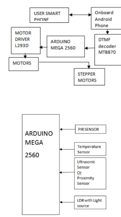
Fig. 3: Robotic control diagram.
Fig. 4: Block diagram for sensor interface.
In the sensor section, ultrasonic sensor is used for obstacle avoidance. If the android mobile is placed vertically, then the inbuilt proximity sensor is used for obstacle avoidance purpose.
It will reduce the circuit complexity as well as the cost. For video transferring part 3G mobile network communication is necessary to view the video without any delay. Cloud computing technique makes the data storage purpose much easier.
With the Temperature sensor attached with LCD display, we can visualize the temperature reading. Light source is provided with the robot and it will illuminate according to the LDR output in which the LDR is connected with relay. Two PIR sensors are attached with the robot. PIR sensors are used to detect the humans. If the PIR sensor issues high output then according to the programming the servo motor turns towards that direction. In that case, proximity sensor which is available with onboard mobile will sense if there is any object in front of it and automatically it will avoid that path. In future, a solar panel can be attached with the system if any emergency power failure happens. If the solar panel is fixed then the programming should be changed accordingly so that the panel is recharged and give supply.
Construction:
Both two wheeled and four wheeled robots can be used. Four wheeled robot is used here. Controlling of four wheeled robot is better when comparing with two wheeled one. They are connected to motor which are driven by motor drivers L293D. The dimension of the robot is 30 x 30 cm (l x b). The power supply is given by a 12V battery which is mounted over the robot. Android mobile (Onboard mobile) is placed over the chassis. It is placed nearby IP camera which is also placed in stand above the chassis where the stand is controlled by servo motor to turn the IP camera. IP camera is used for examining the circumference. Two PIR sensors are used. They are placed at the front end corners of the robot.Light source is placed in front of robot. They are provided LDR sensors with relay to automatically turn on the light source when there is lack of illumination. Ultrasonic sensors are used to avoid the obstacles when the signal is disturbed. Temperature is known by the temperature and humidity sensor.Arduino mega 2560 is attached to the sensors and DTMF decoder.
Working:
Robot movement control:
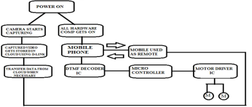
programming the arduino sends the binary code to the motor driver IC L293D so that the motors take the correct turn move in appropriate direction.
B. Live video transfer:
For video transmission part, the IP camera should be provided with password which was set by DLINK software before operation. While operation, the camera needs 3G network to send the videos without any time delay. The network is provided by onboard mobile phone.Cloud computing or "the cloud" focuses on maximizing the effectiveness of the shared resources. Cloud resources are usually not only shared by multiple users but are also dynamically reallocated per demand. This can work for allocating resources to users. The user may wish that his or her information is kept private, but the owner of the remote servers may want to take advantage of it for their own business.
Fig. 5: Block diagram for video transferring.
During surveillance, the camera transfers the video to cloud by CLOUD COMPUTING TECHNIQUE. By logging in DLINK through internet with user id and password, we can monitor the videos provided by IP camera which is provided with robot. No matter where the user is, operation can be done by this method. So CLOUD COMPUTING makes possible the transfer of videos, sound to a larger distance. If the user is available within the Wi-Fi range, then there is no need to the user to follow the above procedure. By getting the mobile application named DLINK, the user can visualize the video through that application. The synchronization between the user mobile and the video camera is done by entering the password in DLINK application which must be same as the password given to IP camera. In this condition, the user can give Wi-Fi network to video camera in case of any internet connection problem.
C. Sensors part:
LDR sensor is attached to the relay so that in case lack of illumination power source will be turned on. The temperature sensor output is given to the LCD and it is placed in front of camera so that the temperature in that area is visible to the user. The maximum temperature sensed by the sensor depends on the material used in the sensor. So user can choose the required sensor. When PIR sensors which are available at the corners detect the human, the IP camera stand turns to the appropriate direction according to the programming by the use of servo motor. Ultrasonic sensor is used in case of network failure. Network failure is considered while no signals are received for a certain period of time. At such period auto mode is enabled means the robot moves without hitting any obstacles and follows the previous command.
Fig. 6: Flow of the complete working.
Applications:
• Emergency rescue operation • Displaying hidden Land mines • Can be used for surveillance • For spying
Future Advancements:
In the proposed system, we can add solar panels in the future to make the robot function with solar energy as external power source and thus full power backup can be achieved.
Conclusion:
The primary purpose of smart phone operated robot is to be acquainted with the information in the locations where we cannot footpace. It is expected that, this system can widely be used in emergency rescue scheme, surveillance and other application sectors those are suggested. If installed with trajectory projections it could be of a wider phenomenal growth in the military.
REFERENCES
Letian Liu, 2013. State Key Lab. of Robot. & Syst., HIT, China” Indoor Surveillance Robot Controlled by a Smart Phone “International Conference on Robotics and Biomimetics (ROBIO) Shenzhen, China, December INSPEC Accession Number: 14161614.
VenkatesanCentral Power Research Institute Bangalore, V.S., 2014. India “GSM CONTROLLED ROBOTICS”2014 International Conference on Advanced Computing & Communication Technologies, Rohtak INSPECAccession Number: 14221240.
Al-Aubidy, K.M., Fac. of Eng., Philadelphia Univ., Amman, Jordan “GPRS-based remote sensing and teleportation of a mobile robot “Systems Hammamet, INSPEC Accession Number: 13709371
Chirag B RVCE, Bangalore India, 2014. “Design and Implementation of Cost Effective Surveillance Robot”, and 2014 Asia-Pacific Conference on Computer Aided System Engineering (APCASE), South Kuta, INSPEC Accession Number: 14666086
Tasmeeh Ahsan, S.M., 2014. “Design and Implementation of a Robotic Vehicle With Real-Time Video Feedback Control via Internet” International Conference on Electrical Engineering and Information & Communication Technology (ICEEICT), INSPEC Accession Number: 14651067
Hou-Tsan Lee, 2011. Dept. of. Inf. Technol., TakMing Univ. of Sci. & Technol., Taiwan “wireless indoor surveillance robotSICE Annual Conference (SICE), Proceedings INSPEC Accession Number:12354289
Yun Chan Cho, 2008. Dept. of Mobile Commun., SungKyunKwan Univ., Suwon “Remote robot controlled system based on DTMF of mobile phone” Industrial Informatics, INDIN 6th IEEE International Conference