ARC-5020
User’s Manual
(4-Port eSATA/USB2.0 to SATA RAID Box)
Areca RAID Box
Copyright Statement
Areca Technology Corporation
© COPYRIGHT 2004
ALL RIGHTS RESERVED. First Edition.
All trademarks are the properties of their respective owners. No
por-Version: 1.1
WARRANTY
The information in this document is subject to change without notice. We make no warranty of any kind regarding this material, including, but
not limited to, the implied warranties or merchantability and fitness for
a particular purpose. Furthermore, we shall not be liable for errors con-tained herein or for incidental or consequential damage in connection with the furnishing, performance, or use of this material.
FCC STATEMENT
This equipment has been tested and found to comply with the limits for a Class B digital device, pursuant to part 15 of the FCC Rules. These limits are designed to provide reasonable protection against interfer-ence in a residential installation. This equipment generates, uses, and can radiate radio frequency energy and, if not installed and used in ac-cordance with the instructions, may cause harmful interference to radio communications. However, there is no guarantee that interference will not occur in a particular installation.
CE Mark
Contents
1. Introduction ... 10
1.1 System Architecture ... 10
1.1.1 eSATA/USB 2.0 Host Interface ... 10
1.1.2 SATA ll Drive Interface ... 11
1.2 RAID Box Controller Board ... 11
1.2.1 Unparalleled Performance ... 11
1.2.2 Unsurpassed Data Availability ... 12
1.2.3 Easy RAID Management ... 12
2. Hardware Installation ... 14
2.1 ARC-5020 RAID box ... 14
2.2 Installation ... 15
2.3 Hot-plug Drive Replacement ... 22
2.3.1 Recognizing a Drive Failure ... 22
2.3.2 Replacing a Failed Drive ... 22
3. Configuration Methods ... 23
3.1 Using local front panel touch-control keypad ... 23
3.2 VT100 terminal (Using the controller’s serial port) ... 25
3.2.1 RAID Box RS-232C Port Pin Assignment ... 25
3.2.2 Start-up VT100 Screen ... 26
3.3 Web browser-based RAID manager ... 29
3.4 Configuration Menu Tree ... 29
4. LCD Configuration Menu ... 31
4.1 Starting LCD Configuration Utility ... 31
4.2 LCD Configuration Utility Main Menu Options ... 32
4.3 Configuring Raid Sets and Volume Sets ... 32
4.4 Designating Drives as Hot Spares ... 33
4.5 Using Easy RAID Configuration ... 33
4.6 Using Raid Set and Volume Set Functions ... 35
4.7 Navigation Map of the LCD ... 36
4.7.1 One-step creation Using LCD Hot Key ... 37
4.7.2 Quick Volume And Raid Setup ... 38
4.7.3 Raid Set Functions ... 39
4.7.3.1 Create A New Raid Set ... 40
4.7.3.2 Delete Raid Set ... 40
4.7.3.3 Expand Raid Set ... 41
4.7.3.5 Activate Incomplete RaidSet ... 42
4.7.3.6 Create Hot Spare Disk ... 42
4.7.3.7 Delete Hot Spare Disk ... 42
4.7.3.8 Display Raid Set Information ... 42
4.7.4 Volume Set Functions ... 43
4.7.4.1 Create Raid Volume Set ... 43
4.7.4.1.1 Volume Name ... 44 4.7.4.1.2 Raid Level ... 44 4.7.4.1.3 Stripe Size ... 44 4.7.4.1.4 Cache Mode ... 45 4.7.4.1.5 Host Channel... 45 4.7.4.1.6 Drive Number ... 45
4.7.4.1.7 SATA Xfer Mode ... 45
4.7.4.1.8 Capacity ... 46
4.7.4.1.9 Initialization Mode ... 46
4.7.4.2 Delete Existed Volume Set ... 46
4.7.4.3 Modify Volume Set Attribute ... 46
4.7.3.3.1 Volume Set Migration ... 47
4.7.4.4 Check Volume Set Consistency ... 48
4.7.4.5 Stop Volume Set Consistency Check ... 48
4.7.4.6 Display Volume Set Information ... 48
4.7.5 Physical Drive Functions ... 48
4.7.5.1 Display Drive Information ... 50
4.7.5.2 Create Pass Through Disk ... 50
4.7.5.3 Modify Pass Through Disk ... 50
4.7.5.4 Delete Pass Through Disk ... 51
4.7.5.5 Identify The Selected Drive ... 51
4.7.6 Raid System Functions ... 51
4.7.6.1 Mute The Alert Beeper ... 53
4.7.6.2 Alert Beeper Setting ... 53
4.7.6.3 Change Password ... 53
4.7.6.4 JBOD/RAID Mode Configuration ... 53
4.7.6.5 Raid Rebuild Priority ... 54
4.7.6.6 Maximum SATA Mode ... 54
4.7.6.7 Host NCQ Setting ... 54
4.7.6.8 HDD Read Ahead Cache ... 55
4.7.6.9 Stagger Power On Control ... 55
4.7.6.10 Spin Down Idle HDD ... 56
4.7.6.11 Empty HDD Slot LED Control ... 56
4.7.6.15 Restart Controller ... 57
4.7.7 Ethernet Configuration ... 58
4.7.7.1 DHCP ... 58
4.7.7.2 Local IP Adress ... 58
4.7.7.3 HTTP Port Number ... 59
4.7.7.4 Telnet Port Number ... 59
4.7.7.5 Ethernet Address ... 59
4.7.8 Show System Events ... 59
4.7.9 Clear all Event Buffers ... 59
4.7.10 Hardware Monitor Information ... 60
4.7.11 System Information ... 60
5. VT-100 Utility Configuration ... 61
5.1 Configuring Raid Sets/Volume Sets ... 61
5.2 Designating Drives as Hot Spares ... 62
5.3 Using Quick Volume /Raid Setup Configuration ... 62
5.4 Using Raid Set/Volume Set Function Method ... 64
5.5 Main Menu ... 66
5.5.1 Quick Volume/Raid Setup ... 67
5.5.2 Raid Set Function ... 69
5.5.2.1 Create Raid Set ... 70
5.5.2.2 Delete Raid Set ... 71
5.5.2.3 Expand Raid Set ... 72
5.5.2.4 Offline Raid Set ... 73
5.5.2.5 Activate Raid Set ... 73
5.5.2.6 Create Hot Spare ... 74
5.5.2.7 Delete Hot Spare ... 74
5.5.2.8 Raid Set Information ... 75
5.5.3 Volume Set Function ... 76
5.5.3.1 Create Volume Set ... 77
5.5.3.1.1 Volume Name ... 78 5.5.3.1.2 Raid Level ... 78 5.5.3.1.3 Capacity ... 79 5.5.3.1.4 Strip Size ... 79 5.5.3.1.5 Host Channel... 80 5.5.3.1.6 Drive Number ... 81 5.5.3.1.7 Cache Mode ... 81
5.5.3.1.8 SATA Xfer Mode ... 82
5.5.3.2 Delete Volume Set ... 82
5.5.3.3 Modify Volume Set ... 83
5.5.3.4 Check Volume Set ... 85
5.5.3.5 Stop Volume Set Check ... 85
5.5.4 Physical Drives ... 86
5.5.3.6 Display Volume Set Info. ... 86
5.5.4.1 View Drive Information ... 87
5.5.4.2 Create Pass-Through Disk ... 87
5.5.4.3 Modify Pass-Through Disk ... 88
5.5.4.4 Delete Pass-Through Disk ... 88
5.5.4.5 Identify Selected Drive ... 88
5.5.5 Raid System Function ... 89
5.5.5.1 Mute The Alert Beeper ... 89
5.5.5.2 Alert Beeper Setting ... 90
5.5.5.3 Change Password ... 91
5.5.5.4 JBOD/RAID Function ... 91
5.5.5.5 Background Task Priority ... 92
5.5.5.6 Maximum SATA Mode ... 93
5.5.5.7 Host NCQ Mode Setting ... 93
5.5.5.8 HDD Read Ahead Cache ... 94
5.5.5.9 Stagger Power On ... 95
5.5.5.10 Spin Down Idle HDD ... 96
5.5.5.11 Empty HDD Slot LED ... 96
5.5.5.12 HDD SMART Status Polling ... 97
5.5.5.13 Auto Activate Raid Set ... 97
5.5.5.14 Capacity Truncation ... 98
5.5.5.15 Terminal Port Config ... 99
5.5.5.16 Update Firmware ... 99 5.5.5.17 Restart Controller ... 100 5.5.6 Ethernet Configuration ... 100 5.5.6.1 DHCP Function ... 101 5.5.6.2 Local IP Address ... 102 5.5.6.3 HTTP Port Number ... 103
5.5.6.4 Telent Port Number ... 103
5.5.6.5 Ethernet Address ... 104
5.5.7 View System Events ... 105
5.5.8 Clear Events Buffer ... 105
5.5.9 Hardware Monitor Information ... 105
5.5.10 System Information ... 106
6. Web Browser-based Configuration ... 108
6.1 Firmware-embedded TCP/IP & web browser-based RAID man-ager (using the controller’s 10/100 LAN port) ... 108
6.2.1 Main Menu ... 110
6.3 Quick Function ... 110
6.3.1 Quick Create ... 110
6.4 RaidSet Functions ... 111
6.4.1 Create Raid Set ... 111
6.4.2 Delete Raid Set ... 112
6.4.3 Expand Raid Set ... 112
6.4.4 Offline Raid Set ... 113
6.4.5 Activate Raid Set ... 113
6.4.6 Create Hot Spare ... 113
6.4.7 Delete Hot Spare ... 114
6.4.8 Rescue RaidSet ... 114
6.5 VolumeSet Functions ... 115
6.5.1 Create Volume Set ... 115
6.5.2 Delete Volume Set ... 118
6.5.3 Modify Volume Set ... 118
6.5.3.1 Volume Expansion ... 119
6.5.3.2 Volume Set Migration ... 119
6.5.4 Check Volume Set ... 119
6.5.5 Stop Volume Set Check ... 119
6.6 Physical Drive ... 120
6.6.1 Create Pass Through ... 120
6.6.2 Modify Pass Through ... 120
6.6.3 Delete Pass Through Disk ... 121
6.6.4 Identify Drive ... 121
6.7 System Controls ... 122
6.7.1 System Configuration ... 122
6.7.2 EtherNet Config ... 126
6.7.3 Alert By Mail Config ... 127
6.7.4 SNMP Configuration ... 128
• SNMP Trap Configurations ... 128
• SNMP System Configurations ... 128
• SNMP Trap Notification Configurations ... 128
6.7.5 View Events/Mute Beeper ... 129
6.7.6 Generate Test Event ... 130
6.7.7 Clear Events Buffer ... 130
6.7.8 Modify Password ... 130
6.7.9 Upgrade Firmware ... 131
6.7.10 Restart Controller ... 131
6.8.3 Hardware Monitor ... 132
Appendix A ... 133
Upgrading Flash Firmware Programming Utility ... 133
Establishing the Connection for the RS-232 ... 133
Upgrade Firmware Through ANSI/VT-100 Terminal Emulation .... 134
Upgrade Firmware Through Web Browser Manager (LAN Port) ... 136
Appendix B ... 138
SNMP Operation & Definition ... 138
Appendix C ... 140
Technical Support ... 140
Appendix D ... 141
Event Notification Configurations ... 141
A. Device Event ... 141
B. Volume Event ... 142
C. RAID Set Event ... 143
D. Hardware Monitor Event ... 143
Appendix E ... 145
RAID Concept ... 145
RAID Set ... 145
Volume Set ... 145
Easy of Use Features ... 146
Instant Availability/Background Initialization ... 146
Array Roaming ... 146
Online Capacity Expansion ... 146
Online RAID Level and Stripe Size Migration ... 148
Online Volume Expansion ... 148
High availability ... 149
Global Hot Spares ... 149
Hot-Swap Disk Drive Support ... 150
Auto Declare Hot-Spare ... 150
Auto Rebuilding ... 151
Adjustable Rebuild Priority ... 151
High Reliability ... 152
Hard Drive Failure Prediction ... 152
Auto Reassign Sector ... 152
Consistency Check ... 153
Data Protection ... 153
RECOVERY ROM ... 153
Understanding RAID ... 154
RAID 10 ... 155
RAID 3 ... 156
RAID 5 ... 157
JBOD ... 157
INTRODUCTION
1. Introduction
The ARC-5020 RAID box is a high-performance SATA ll drive bus disk
array controller. When properly configured, the RAID box can provide
non-stop service with a high degree of fault tolerance through the use of RAID technology and advanced array management features. The RAID box unleashes a truly innovative eSATA (3.0Gbps)/USB2.0 solu-tion for use with your PC and Mac. The HOST interface on the host may be located either on the system board, or on a plug-in host bus adapter (HBA) card. With the host SATA controller supported
port multiplier function, both eSATA and USB2.0 host channel can support multiple volumes (up to 4) by Areca’s target mode multiplier emulation.
The RAID box allows easy scalability from JBOD to RAID. It can be
configured to RAID levels 0, 1, 10, 3, 5, Single Disk or JBOD. The RAID function allows one HDD failure without impact on the exist-ing data and failed drive data can be reconstructed from the
remain-ing data and parity drives. RAID configuration and monitorremain-ing can be
done through the LCD front control panel, serial port or LAN port. The controller unit is most cost-effective SATA disk drive RAID box with completely integrated high-performance and data-protection capabili-ties, which meet the performance and features of a midrange storage product at an entry-level price.
1.1 System Architecture
1.1.1 eSATA/USB 2.0 Host Interface
The ARC-5020 RAID box’s host interface appears to the host sys-tem as a SATA ll or UBS2.0 target device. Your ARC-5020 RAID
Host
Controller boardRAID Box
SATAll Drives
(Max 4)ARC-5020
INTRODUCTION
use of shielded cables outside the PC. The eSATA cable is Fully-shielded cable with separation of the outer shielding (for chassis ground) and signal ground, Hot-plugging supported and Maximum length increased to 2 meters. The USB 2.0 or Hi-Speed USB provides an even greater enhancement in performance—up to 40 times faster than USB 1.1, with a design data rate of 480 Mbps.
1.1.2 SATA ll Drive Interface
The ARC-5020 RAID box communicates directly with the array’s 4 SATA ll drives via a built-in SATA interface. When the host is di-rectly controlling the drives, the RAID box controller board trans-lates all communications between the HOST eSATA/USB2.0 and SATA ll devices.
1.2 RAID Box Controller Board
The ARC-5020 RAID box incorporates onboard high performance 400MHz storage processors and on-board DDR2-400 SDRAM mem-ory to deliver true hardware RAID. Designed and leveraged with Areca’ existing high performance solution, this controller delivers high-capacity performance at the best of cost/performance value. Hardware RAID controllers have their own local RAID processor
on-board, plus dedicated onboard cache for full hardware offloading of
RAID-processing functions. The ability of hardware RAID controllers to rebuild an array in the event of a drive failure is superior to what software RAID controllers offer.
1.2.1 Unparalleled Performance
ARC-5020 RAID box unleashes the power of 3.0Gbps performance and NCQ support on the eSATA host port. The eSATA port delivers in excess of 210MB/s sustained RAID 5 reads and over 176MB/s RAID 5 sequential writes. The result is superior overall perfor-mance compared to other 4 bay eSATA solution. High transfer rates make ARC-5020 RAID box well suited for audio/video appli-cation, especially the rapidly growing demand from the Mac Video Editing markets. With the host SATA controller supported
INTRODUCTION
1.2.2 Unsurpassed Data Availability
The ARC-5020 RAID box provides RAID levels 0, 1, 10, 3, 5,
Single Disk or JBOD RAID configurations. Its high data availabil -ity and protection derives from the following capabilities: Online RAID Capacity Expansion, Array Roaming, Online RAID Level / Stripe Size Migration, Global Online Spare, Automatic Drive Fail-ure Detection, Automatic Failed Drive Rebuilding, Disk Hot Swap, Online Background Rebuilding, Instant Availability/Background Initialization, Auto Reassign Sector and Redundant Flash Image. Areca greater than two TB support allows for very large volume set application in 64-bit environment such as data-mining and managing large databases.
1.2.3 Easy RAID Management
Manual configuration and monitoring can be done through the
LCD Control Panel, RS-232 and LAN port. The LCD Hot-Key
sup-ports one-step creation RAID configuration to simplify the firstly
setup of ARC-5020 RAID box. It’s API library supports customer to write its own monitor utility. The hardware monitor can monitor enclosure voltage, temperature and FAN.
Adapter Architecture
• 400MHz storage I/O processor
• Unleash the power of 3.0Gbps and NCQ on the eSATA host port
• NVRAM for RAID configuration & transaction log
• Write-through or write-back cache support
• Redundant flash image for controller availability
• RAID level 0, 1, 10, 3, 5, Single Disk or JBOD • Multiple RAID selection
• Up to 4 volumes (Target mode multiplier emulation) • Online array roaming
• Online RAID level/stripe size migration
• Online capacity expansion and RAID level migration simultaneously
• Online dynamic volume set capacity expansion • Instant availability and background initialization • Automatic insertion/removal detection and rebuild
INTRODUCTION
• Support SMART, NCQ, and OOB staggered spin-up capable drives
Monitors/Notification
• Push Buttons and LCD Display Panel for setup and status • Environment and drive failure indication through LCD, LED and alarm buzzer
• Keep silent and adequate air flow and cooling by intelligent
cooling fan speed controller RAID Management
• Field-upgradeable firmware in flash ROM via RS-232 and LAN
port
• LCD Hot-Key supports one-step creation RAID configuration
• Firmware-embedded manager via RS-232 port
• Firmware-embedded Browser-based RAID manager, SMTP manager, SNMP agent and Telnet function via LAN port
• Support RAID box’s API library for customer to write its own AP
Model Name ARC-5020
Host Interface eSATA (3.0Gbps) & USB2.0
RAID Support RAID level 0, 1, 10, 3, 5, Single Disk or JBOD Disk Interface 4 x SATAII 3Gbps
Enclosure
Manage-ment LAN port, RS-232 port and LCD
Cool Fan 3800rpm/0.4A
Form Factor Compact – 4 Disk Tower
Power Supply/In/out 180W / 90-265V AC / +5V/9A, +12V/9A, +3.3V/4.5A Dimension 4.84 x 6.51 x 9.11 / 123 x 165.6 x 232 mm
HARDWARE INSTALLATION
2. Hardware Installation
2.1 ARC-5020 RAID box
The ARC-5020 RAID box supports four SATA ll channels. For SATA ll drive each channel can run up to 300MB/S.
Front View Rear View
1. Disk Fault LED 2. Disk Activity LED
3. Power and Global Fault LED
4. System Fan 5. RS232 Port 6. LAN Port
7. USB Port (Drive) 8. USB Port (Host) 9. eSATA port
10. Power Supply Fan 11. On/Off Switch 12. Power Connector
HARDWARE INSTALLATION
2.2 Installation
Step 1. Install the Drives in the ARC-5020 RAID Box
1. Gently slide the drive tray out from the ARC-5020 RAID box.
2. Install the drive into the drive tray and secure the drive to the drive tray by four of the mounting screws.
Figure 2-1, Secure the drive to the drive tray
3. After all drives are in the drive tray, slide all of them back into the ARC-5020 RAID box and make sure you latched the drive trays.
Note:
Please secure four of the mounting screws to the tray, other-wise the ARC-5020 may produce an annoying BUZZ sound in few environments.
HARDWARE INSTALLATION
Step 2. Connect the Power
An AC power cord was supplied with your ARC-5020 RAID box.
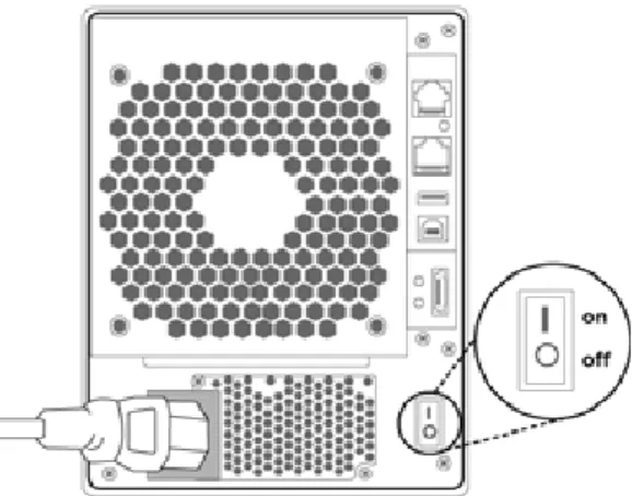
This is the only power cord recommended for use with this prod-uct. Connect this power cable to a grounded electrical outlet and to the ARC-5020 RAID box. Turn on the AC power switch from the back of ARC-5020 RAID box.
Figure 2-3, Connect the power cable to a grounded electrical outlet and to the ARC-5020 RAID box.
Step 3. Configure RAID Subsystem
The ARC-5020 RAID box is normally delivered with LCD
pre-in-stalled. Your ARC-5020 RAID box can be configured by using the LCD with keypad, a serial device (terminal emulation) or LAN port.
• Method 1: LCD Panel with Keypad
You can use LCD front panel and keypad function to simply cre-ate the RAID volume. The LCD status panel also informs you of the disk array’s current operating status at a glance. LCD
Hot-Key supports one-step creation RAID configuration. For addi
HARDWARE INSTALLATION
The LCD provides a system of screens with areas for informa-tion, status indicainforma-tion, or menus. The LCD screen displays up to two lines at a time of menu items or other information.
The Initial screen is as following:
• Method 2: RS-232 Port Connection
The ARC-5020 RAID box can be configured via a VT-100 com -patible terminal or a PC running a VT-100 terminal emulation program. You can attach a serial (Character-Based) terminal or server com port to the RAID box for access to the text-based setup menu. For additional information on using the RS-232
port to configure the RAID box see the Chapter 5 of VT-100 Util
-ity Configuration.
• Method 3: LAN Port Connection
The ARC-5020 RAID box has embedded the TCP/IP & Web
Browser-based RAID manager in the .firmware. User can re
-mote manage the RAID box without adding any user specific
software (platform independent) via standard web browsers di-rectly connected to the 10/100 Ethernet RJ45 LAN port. For
ad-ditional information on using the LAN port to configure the RAID box see the Chapter 6 of Web Browser-Based Configuration.
Step 4. Connect to Host Computer
Once the ARC-5020 RAID box has finished the initialization of the
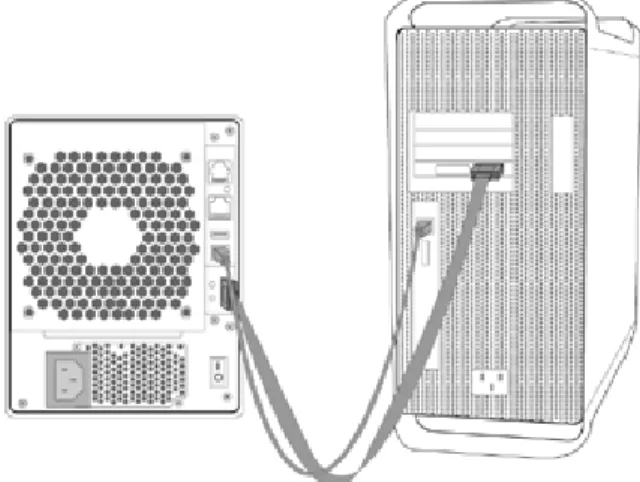
array, then you can connect it to a host computer. The ARC-5020 RAID box can be connected to a host computer through the Hi-Speed USB 2.0 or eSATA interface. User can use both interfaces connected to the host. When the volume set is ready for system accesses, connect the USB2.0, or/and eSATA cable to the
HARDWARE INSTALLATION
Figure 2-4, Figure 2-3, Connect ARC-5020 RAID box to the host computer.
• eSATA Cables and Connectors
The ARC-5020 RAID box uses the latest in eSATA technology, allowing interface (or bus) transfer rates of up to 3.0Gbps. The eSATA was developed for the use of shielded cables outside the PC. The eSATA cable is fully-shielded cable with separation of the outer shielding (for chassis ground) and signal ground, Hot-plug-ging supported and maximum length increased to 2 meters. Since the market demand for eSATA external storage is on the rise, a system released almost has added eSATA connectors in the main-board connector requirements or install a PCI Host controller with external eSATA connection. This provides an easy and reliable way to equip a system with an external SATA connection.
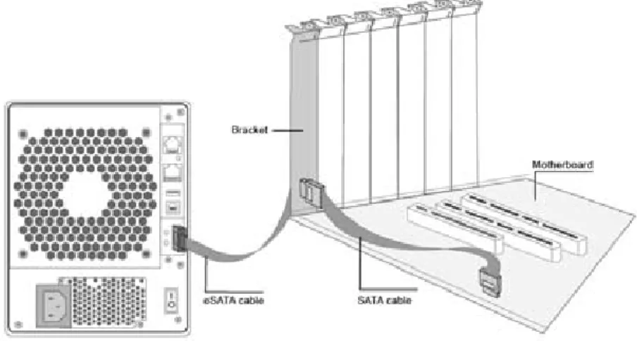
If systems without supporting eSATA connector, you can also use a cable from an internal SATA connector up to a receptacle on a PCI bracket, as shown in Figure 2-5. In this case, it should be noted that the signal from internal controller to the eSATA con-nector should meet eSATA the electrical compliance requirements outlined. Areca would suggest utilize a PCI or PCIe SATA host controller that supports hot swap, NCQ and SATA PM connections. This can make user to leverage above features supported on the
HARDWARE INSTALLATION
Figure 2-5, An eSATA host connection enabled with a bracket that is cabled to a motherboard SATA connector.
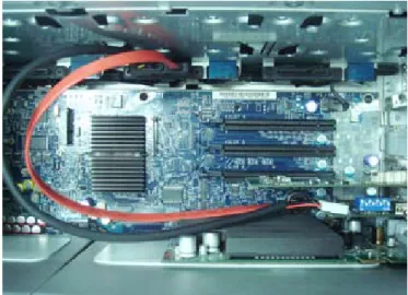
The Mac Pro internal hard drive backplane mounting system is a very nice feature. It comes with four trays and supports up to four internal 3.5" SATA hard drives. Users simply add Areca extension cable from those empty drive backplane to Areca ARC-5020-3 re-driver board to have the eSATA connector. Sim-ply screw empty slot bracket to fasten the ARC-5020-3 re-driver board. It does not occupy one useable slot. The backplane con-nector provides power and SATA signal to re-driver board. This can guarantee the signal from Mac pro internal SATA backplane connector to the eSATA connector can meet eSATA the electrical compliance requirements. This low cost solution can boost the performance better than the currently PCIe x1 SATA eSATA host adapter.
HARDWARE INSTALLATION
Figure 2-6, PCIe adapter card that supports an external SATA interface in a notebook.
In notebook applications, there is an easy way to enable external Serial ATA connectivity through the use of a PCMCIA based con-troller or a PCIe card. An example of PCIe type of interconnect is shown in Figure 2-6.
HARDWARE INSTALLATION
• Hi-Speed USB 2.0 Cables and Connectors
The ARC-5020 RAID box uses the USB 2.0 or Hi-Speed USB, providing an even greater enhancement in performance—up to 40 times faster than USB 1.1, with a design data rate of 480 Mbps. Your ARC-5020 RAID box is shipped with a Hi-Speed USB 2.0 cable, to ensure maximum data transfer performance when connected to a Hi-Speed USB 2.0 port. This cable can also work when connected to a USB port, but drive performance will be limited to USB 1.1 transfer rates.
Step 5. Turn on Host Computer Power
Safety checks the installation. Connect all power code. Turn on the AC power switch at the rear of host computer then press the power button at the front of the host computer.
Step 6. Format, Partition and Mount the ARC-5020 RAID Box Volumes
After you create a unit, it needs to be partitioned, formatted, and mounted by the operating system. There are various steps, that is depend on what operating system you are using (Win-dows, Linux, FreeBSD or Mac, etc.). Detailed steps for each operating system are provided on their disk utility. After that, the ARC-5020 RAID box can be fully used.
Note:
1. ARC-5020 RAID box can support multiple volumes (up to 4) by Areca’s target mode multiplier emulation if host controllers support port multiplier function.
2. The eSATA without port multipliers function will be able to recognize one hard drive in the ARC-5020 RAID box.
3. SATA is faster than FireWire 800 and more reliable. Some
Mac users have lost data as a result of FireWire firmware
changes and that risk continues to exist each time FireWire is altered. That risk does not exist with SATA enclosures as no bridge board is required.
HARDWARE INSTALLATION
Note:
It is a good idea to turn on your ARC-5020 RAID box before turning on the host computer. This will insure that the host computer recognizes the volumes and drives in the
ARC-5020 RAID box. If you turn on the host computer first,
be sure of your host controller supporting hot-plug function or rescan command to recognize the ARC-5020 RAID box again.
2.3 Hot-plug Drive Replacement
The ARC-5020 RAID box supports the ability of performing a hot-swap drive replacement without powering down the system. A disk can be disconnected, removed, or replaced with a differ-ent disk without taking the system off-line. The ARC-5020 RAID box rebuilding will be processed automatically in the background. When a disk is hot swap, the ARC-5020 RAID box may no longer be fault tolerant. Fault tolerance will be lost until the hot swap drive is subsequently replaced and the rebuild operation is com-pleted.
2.3.1 Recognizing a Drive Failure
A drive failure can be identified in one of the following ways:
1. An error status message lists failed drives.
2. Fault LED illuminates on the front of driver tray if failed drives are inside.
2.3.2 Replacing a Failed Drive
With our ARC-5020 RAID box drive tray, you can replace a defec-tive physical drive while your computer is still operating. When a new drive has been installed, data reconstruction will be au-tomatically started to rebuild the contents of the disk drive. The capacity of the replacement drives must be at least as large as
CONFIGURATION METHOD
3. Configuration Methods
After the hardware installation, the SATA disk drives connected to
the RAID box must be configured and the volume set units initialized
before they are ready to use. This can be accomplished by one of the following methods:
• Front panel touch-control keypad.
• VT100 terminal connected through the controller’s serial port. • Firmware-embedded & web browser-based RAID manager/SNMP gent/SMTP via the controller’s 10/100 LAN port.
Those user interfaces can access the built-in configuration and admin
-istration utility that resides in the controller’s firmware. They provide
complete control and management of the controller and disk arrays, eliminating the need for additional hardware or software.
Note:
The RAID box allows only one method to access menus at a time.
3.1 Using local front panel touch-control
keypad
The front panel keypad and liquid crystal display (LCD) is the
pri-mary user interface for the RAID box. All configuration and man -agement of the controller and its properly connected disk arrays can be performed from this interface.
The front panel keypad and LCD are connected to the RAID box
to access the built-in configuration and administration utility that resides in the controller’s firmware. Complete control and manage -ment of the array’s physical drives and logical units can be per-formed from the front panel, requiring no additional hardware or software drivers for that purpose.
CONFIGURATION METHOD
A touch-control keypad and a liquid crystal display (LCD) mounted on the back panel of the RAID box is the primary operational in-terface and monitor display for the disk array controller. This user
interface controls all configuration and management functions for
the RAID box it is properly connected.
The LCD provides a system of screens with areas for information, status indication, or menus. The LCD screen displays up to two lines at a time of menu items or other information.
The initial screen as the following:
Function Key Definitions:
The four function keys at the button of the front panel perform the following functions:
Key Function
Up Arrow Use to scroll the cursor Upward/Rightward Down Arrow Use to scroll the cursor Downward/Leftward
ENT Key Submit Select ion Function (Confirm a selected Item)
ESC Key Return to Previous Screen (Exit a selection configuration)
Panel LED Normal Status Problem Indication Power LED Solid green, when power on Unlit, when power on
Busy LED Blinking amber during host
ac-cesses ARC-5020 Unlit or never flicker
There are a variety of failure conditions that cause the RAID box monitoring LED to light. Following table provides a summary of the front panel LED.
CONFIGURATION METHOD
3.2 VT100 terminal (Using the controller’s
serial port)
The serial port on the RAID box’s back panel can be used in VT100 mode. The provided interface cable converts the RS232 signal of the 6-pin RJ11 connector on the RAID box into a 9-pin D-Sub
female connector. The firmware-based terminal array management
interface can access the array through this RS-232 port. You can attach a VT-100 compatible terminal or a PC running a VT-100 ter-minal emulation program to the serial port for accessing the text-based Setup Menu.
3.2.1 RAID Box RS-232C Port Pin Assignment
To ensure proper communications between the RAID box and the
VT-100 Terminal Emulation, Please configure the VT100 terminal
emulation settings to the values shown below:
Terminal requirment Connection Null-modem cable
Baud Rate 115,200
Data bits 8
Stop 1
Flow Control None
The controller RJ11 connector pin assignments are defined as be -low.
Action
Pin Description Pin Description
1 RTS 4 GND
2 RXD 5 GND
3 TXD 6 GND
For additional information on using the LCD panel and keypad to
configure the RAID controller see ‘‘LCD Configuration Menu” on
CONFIGURATION METHOD
Key Function
Arrow Key Move cursor
Enter Key Submit selection function ESC Key Return to previous screen
L Key Line draw
X Key Redraw
Keyboard Navigation
The following definition is the VT-100 RAID configuration utility
keyboard navigation.
3.2.2 Start-up VT100 Screen
By connecting a VT100 compatible terminal, or a PC operating in an equivalent terminal emulation mode, all RAID box monitoring,
configuration and administration functions can be exercised from
the VT100 terminal.
There are a wide variety of Terminal Emulation packages, but for the most part they should be very similar. The following setup procedure is an example Setup VT100 Terminal in Windows sys-tem using Hyper Terminal use Version 3.0 or higher.
Step 1. From the Desktop open the start menu. Pick Programs, Accessories, Communications and Hyper Terminal. Open Hyper Terminal (requires version 3.0 or higher)
Step 2. Open HYPERTRM.EXE and enter a name for your Termi-nal. Click OK.
CONFIGURATION METHOD
Step 3. Select an appropriate connecting port in your Terminal.
Click OK. Configure the port parameter settings. Bits per second:
“115200”, Data bits: “8”, Parity: ”None”, Stop bits: “1”, Flow control:” None”. Click “OK”
Step 4. Open the File menu, and then open Properties.
CONFIGURATION METHOD
Step 6. Open the Settings Tab. Function, arrow and ctrl keys act as: Terminal Keys, Backspace key sends: “Crtl+H”, Emulation: VT100, Telnet terminal: VT100, Back scroll buffer lines: 500. Click OK.
Now, the VT100 is ready to use.
After you have finished the VT100 Terminal setup, you may press
“ X “ key (in your Terminal) to link the RAID subsystem and Ter-minal together.
Press” X ” key to display the disk array Monitor Utility screen on
CONFIGURATION METHOD
3.4
Configuration Menu Tree
The following is an expansion of the menus in configuration Util -ity that can be accessed through the LCD panel, RS-232 serial port and LAN port.
3.3 Web browser-based RAID manager
To configure ARC-5020 RAID box on a local or remote machine,
you need to know its IP Address. The IP address will default
show in the LCD screen or Ethernet Configuration option on the VT100 utility configration. Launch your firmware-embedded TCP/
IP & Web Browser-based RAID manager by entering http://[IP Address] in the web browser.
The provided LAN interface cable connects the ARC-5020 RAID box LAN port into a LAN port from your local network. Use only shield cable to avoid radiated emission that may cause interruptions. To ensure proper communications between the RAID subsystem and Web browser-based RAID management, Please connect the RAID box Ethernet LAN port to any LAN switch port.
The ARC-5020 RAID box has embedded the TCP/IP & Web
Browser-based RAID manager in the firmware. User can remote manage the RAID box without adding any user specific software
(platform independent) via standard web browsers directly connected to the 10/100 Ethernet RJ45 LAN port.
The Storage Console current configuration screen displays the current configuration of your ARC-5020 RAID box. Detail
procedures please refer to the Chapter 6 Web Browser-based
configuration method.
Note:
You must be logged in as administrator with local admin rights
on the remote machine to remotely configure it.
The RAID box default user name is “admin” and the password is “0000”.
CONFIGURATION METHOD
Note:
Ethernet Configuration, Alert By Mail Config, and SNMP Config can only be set in the web-based configuration.
LCD CONFIGURATION MENU
4. LCD Configuration Menu
After the hardware installation, the disk drives connected to the RAID
box must be configured and the volume set units initialized before they
are ready to use. This can be also accomplished by the Front panel touch-control keypad.
The LCD module on the backside can access the built-in configuration and administration utility that resides in the controller’s firmware.
To complete control and management of the array’s physical drives and logical units can be performed from the front panel, requiring no additional hardware or software drivers for that purpose.
The LCD provides a system of screens with areas for information, status indication, or menus. The LCD screen displays up to two lines at a time of menu items or other information.
The LCD display back panel function keys are the primary user interface for the RAID box. Except for the "Firmware update", all
configurations can be performed through this interface.
Function Key Definitions
The four function keys at the back panel of the button perform the following functions:
Key Function
Up Arrow Use to scroll the cursor Upward/Rightward Down Arrow Use to scroll the cursor Downward/Leftward
ENT Key Submit Select ion Function (Confirm a selected Item)
ESC Key Return to Previous Screen (Exit a selection configuration)
4.1
Starting LCD Configuration Utility
After power on the ARC-5020 RAID box, press ENT to verify pass-word for entering the main menu from LCD panel. Using the UP/ DOWN buttons to select the menu item, then press ENT to
LCD CONFIGURATION MENU
4.2
LCD Configuration Utility Main Menu
Options
Select an option, related information or submenu items to display beneath it. The submenus for each item are explained on the sec-tion 4.7.2. The configuration utility main menu options are:
Option Description
Quick Volume And Raid Set
Setup Create a default configurations which are based on the number of physical disk installed Raid Set Functions Create a customized raid set
Volume Set Functions Create a customized volume set Physical Drive Functions View individual disk information Raid System Functions Setting the raid system configurations
Ethernet Configuration Ethernet LAN setting
Show System Events Record all system events in the buffer Clear All Event Buffers Clear all event buffer information Hardware Monitor Information Show all system environment status Show System information View the controller information
Step Action
1 Designate hot spares/pass-through (optional)
2 Choose a configuration method
3 Create raid set using the available physical drives
4 Define volume set using the space in the raid set
5 Initialize the volume set and use volume set in the host OS
4.3
Configuring Raid Sets and Volume Sets
You can use “Quick Volume And Raid Set Setup" or "Raid Set Functions" and "Volume Set Functions" to configure raid sets and volume sets from LCD panel. Each configuration method requires a different level of user input. The general flow of operations for raid set and volume set configuration is:
LCD CONFIGURATION MENU
4.4 Designating Drives as Hot Spares
To designate drives as hot spares, press ENT to enter the Main menu. Press UP/DOWN buttons to select the “Raid Set Functions”
option and then press ENT. All raid set functions will be displayed. Press up and down arrow to select the “Create Hot Spare Disk” op -tion and then press ENT. The first unused physical device connect -ed to the current RAID box appears. Press UP/DOWN buttons to scroll the unused physical devices and select the target disk to as-sign as a Hot Spare and press ENT to deas-signate it as a hot spare.
4.5
Using Easy RAID Configuration
In “One-step creation” or “Quick Volume And Raid Setup” con
-figuration, the raid set you create is associated with exactly one
volume set, and you can modify the RAID Level, Stripe Size, and Capacity. Designating drives as Hot Spares will also combine with RAID level in this setup.
The volume set default settings will be:
The default setting values can be changed after configuration is
completed.
Parameter Setting
Volume Name Volume Set#00
Host Channel/ Drive Select SATA/0
Cache Mode Write Back
SATA Xfer Mode SATA300+NCQ
Follow the steps below to create raid set using ”One-step creation ” “Quick Volume And Raid Setup” configuration:
Step Action
1 Using “one-step creation” or choose “Quick Volume And Raid Setup” from
the main menu. The available RAID levels with hot spare for the current volume set drive are displayed.
LCD CONFIGURATION MENU
2 Recommend use drives have same capacity in a specific array. If you use
drives with different capacities in an array, all drives in the raid set will select the lowest capacity of the drive in the raid set.
The numbers of physical drives in a specific array determine the RAID
levels that can be implemented with the array. RAID 0 requires 1 or more physical drives RAID 1 requires at least 2 physical drives RAID 1+Spare requires at least 3 physical drives RAID 3 requires at least 3 physical drives RAID 5 requires at least 3 physical drives RAID 3 +Spare requires at least 4 physical drives RAID 5 + Spare requires at least 4 physical drives
Using UP/DOWN buttons to select RAID level for the volume set and press ENT to confirm it.
3 Using UP/DOWN buttons to create the current volume set capacity size and press ENT to confirm it. The available stripe sizes for the current
volume set are displayed.
4 Using UP/DOWN buttons to select the current volume set stripe size and press ENT key to confirm it. This parameter specifies the size of
the stripes written to each disk in a RAID 0, 1, 10, or 5 volume set. You can set the stripe size to 4 KB, 8 KB, 16 KB, 32 KB, 64 KB, or 128 KB. A larger stripe size provides better-read performance, especially if your computer does mostly sequential reads. However, if you are sure that your computer does random read requests more often, choose a small stripe size.
5 When you finished defining the volume set, press ENT to confirm the “One-Step Creation“ or “Quick Volume And Raid Set Setup” function.
6 Press ENT to define “FGrnd Init (Foreground initialization)” or press ESC
to define “BGrnd Init (Background initialization)“. When “FGrnd Init", the
initialization proceeds must be completed before the volume set ready for system accesses. When “BGrnd Init", the initialization proceeds as a background task, the volume set is fully accessible for system reads and writes. The operating system can instantly access to the newly created arrays without requiring a reboot and waiting the initialization complete. 7 Initialize the volume set you have just configured.
8 If you need to add additional volume set, using main menu “Create
LCD CONFIGURATION MENU
4.6 Using Raid Set and Volume Set
Func-tions
In “Raid Set Function”, you can use the create raid set function to generate the new raid set. In “Volume Set Function”, you can use
the create volume set function to generate its associated volume set and parameters. If the current RAID box has unused physical
devices connected, you can choose the “Create Hot Spare” option in the “Raid Set Function” to define a global hot spare.
Select this method to configure new raid sets and volume sets. This configuration option allows you to associate volume set with partial
and full raid set.
Step Action
1 To setup the Hot Spare (option), choose “Raid Set Function” from the main menu. Select the “Create Hot Spare” and press ENT to set the Hot Spare.
2 Choose “Raid Set Function” from the main menu. Select the “Create Raid
Set” and press ENT.
3 Select a drive for raid set from the SATA drive connected to the ARC-5020 4 Press UP/DOWN buttons to select specific physical drives. Press the ENT
key to associate the selected physical drive with the current raid set.
Recommend use drives has same capacity in a specific raid set. If you use
drives with different capacities in an array, all drives in the raid set will select the lowest capacity of the drive in the raid set.
The numbers of physical drives in a specific raid set determine the RAID
levels that can be implemented with the raid set. RAID 0 requires 1 or more physical drives per raid set. RAID 1 requires at least 2 physical drives per raid set.
RAID 1 + Spare requires at least 3 physical drives per raid set. RAID 3 requires at least 3 physical drives per raid set.
RAID 5 requires at least 3 physical drives per raid set.
RAID 3 + Spare requires at least 4 physical drives per raid set. RAID 5 + Spare requires at least 4 physical drives per raid set.
5 After adding physical drives to the current raid set as desired, press ENT
to confirm the “Create Raid Set” function.
6 An edit the raid set name screen appears. Enter 1 to 15 alphanumeric
characters to define a unique identifier for a raid set. The default raid set
name will always appear as Raid Set. #. Press ENT to finish the name
LCD CONFIGURATION MENU
7 Press ENT when you are finished creating the current raid set. To contin
-ue defining another raid set, repeat step 3. To begin volume set configu -ration, go to step 8.
8 Choose “Volume Set Functions” from the Main menu. Select the “Create
Volume Set” and press ENT .
9 Choose one raid set from the screen. Press ENT to confirm it.
10 The volume set attributes screen appears:
The volume set attributes screen shows the volume set default configura
-tion value that is currently being configured. The volume set attributes
are: Volume Name, Raid Level, Stripe Size, Cache Mode, HOST Channel, Drive Number and SATA Xfer Mode.
All value can be changing by the user. Press the UP/DOWN buttons to select the attributes. Press the ENT to modify each attribute of the de-fault value. Using UP/DOWN buttons to select attribute value and press the ENT to accept the default value.
11 After user completed modifying the attribute, press ESC to enter the se-lect capacity for the volume set. Using the UP/DOWN buttons to set the volume set capacity and press ENT to confirm it.
12 When you finished defining the volume set, press ENT to confirm the Cre -ate function.
13 Press ENT to define “FGrnd Init (Foreground initialization)” or press ESC to define “BGrnd Init (Background initialization)“. The controller will
be-gin to initialize the volume set, you have just configured. If space remains in the raid set, the next volume set can be configured. Repeat steps 8 to 13 to configure another volume set.
4.7 Navigation Map of the LCD
The password option allows user to set or clear the raid subsys-tem’s password protection feature. Once the password has been
set, the user can only monitor and configure the raid subsystem
by providing the correct password. The password is used to pro-tect the ARC-5020 RAID box from unauthorized entry. The RAID box will check the password only when entering the Main menu from the initial screen. The RAID box will automatically go back to the initial screen when it does not receive any command in twenty seconds. The RAID box password is default setting at 0000 by the
LCD CONFIGURATION MENU
Figure 4.7-1
4.7.1 One-step creation Using LCD Hot Key
This section explains how to use the LCD Hot-Key one-step
creation RAID configuration to configure your ARC-5020 RAID box. It is a menu-driven program, residing in the firmware,
which allows you to scroll through various menus and submenus
and select among the predetermined configuration options. This
function provides an easy way to enter the “Quick Volume/Raid
Setup” even the member disk of ARC-5020 having RAID set
existed. It only needs a few keystrokes to complete the RAID set and volume set creation.
When starting an ARC-5020 RAID box, it will display the following message on the LCD during the startup:
LCD CONFIGURATION MENU
The LCD configuration manager starts the Hot-Key one-step creation RAID configuration by pressing DOWN button three times. If you do not use the one-step creation, press ENT to start
the main menu of LCD configuration immediately.
The figure 4.7.1-1 is the flow chart of the Hot-Key one-step creation RAID configuration. This option creates a RAID set with
the following properties:
1. All of the physical disk drives are contained in a RAID set. 2. The RAID levels associated with hot spare, capacity, and stripe
size are selected during the configuration process.
3. A single volume set is created and consumed all or a portion of the disk capacity available in this RAID set.
4. If you need to add additional volume set, using main menu
“Volume Set functions”. Detailed procedure refer to this chapter
section 4.6.
Figure 4.7.1-1
4.7.2 Quick Volume And Raid Setup
“Quick Volume And Raid Setup” is the fastest way to prepare a
raid set and volume set. It only needs a few keystrokes to com-plete it. Although disk drives of different capacity may be used in the raid set, it will use the smallest capacity of the disk drive as the capacity of all disk drives in the raid set. The “Quick Volume
-LCD CONFIGURATION MENU
1. All of the physical disk drives are contained in a raid set. 2. The raid levels associated with hot spare, capacity, and stripe
size are selected during the configuration process.
3. A single volume set is created and consumed all or a portion of the disk capacity available in this raid set.
4. If you need to add additional volume set, using main menu
“Volume Set functions”. Detailed procedure refer to this chapter section 4.6.
4.7.3 Raid Set Functions
User manual configuration can complete control of the raid set
setting, but it will take longer time to complete than the “Quick
Volume And Raid Setup” configuration. Select the “Raid Set Functions” to manually configure the raid set for the first time or deletes existing raid set and reconfigures the raid set.
To enter a “Raid Set Functions”, press ENT to enter the Main menu. Press UP/DOWN buttons to select the “Raid Set
Func-tions” option and then press ENT to enter further submenus. All raid set submenus will be displayed.
LCD CONFIGURATION MENU
Figure 4.7.3-1
4.7.3.1 Create A New Raid Set
For detailed procedure please refer to chapter section 4.6.
4.7.3.2 Delete Raid Set
Press UP/DOWN buttons to choose the “Delete Raid Set” op -tion. Using UP/DOWN buttons to select the raid set number that user want to delete and then press ENT to accept the raid
set number. The confirmation screen appears, then press ENT
to accept the delete raid set function. The double confirmation
screen appears, then press ENT to make sure of the delete ex-isted raid set function
LCD CONFIGURATION MENU
Note:
1. Once the “Expand Raid Set” process has started, user
can not stop it. The process must be completed.
2. If a disk drive fails during raid set expansion and a hot spare is available, an auto rebuild operation will occur after the raid set expansion completes.
4.7.3.3 Expand Raid Set
Instead of deleting a raid set and recreating it with additional
disk drives, the “Expand Existed Raid Set” function allows the
user to add disk drives to the raid set that was created.
To expand existed raid set, press UP/DOWN buttons to choose
the “Expand Raid Set” option. Using UP/DOWN buttons to select the raid set number that user want to expand and then press ENT to accept the raid set number. If there is an available
disk, then the “Select Drive IDE Channel x” appears. Using up and down arrow to select the target disk and then press ENT to select it. Press ENT to start expanding the existed raid set. The
new add capacity will be define one or more volume sets. Follow the instruction presented in the “Volume Set Function” to create
the volume sets.
Migrating occurs when a disk is added to a raid set. Migration status is displayed in the raid status area of the “Raid Set
infor-mation” when a disk is added to a raid set. Migrating status is
also displayed in the associated volume status area of the vol-ume set information when a disk is added to a raid set
4.7.3.4 Offline RAID Set
Press UP/DOWN buttons to choose the “Offline RAID Set”
option. This function is for coutomer being able to mount and remount a multi-disk volume. All Hdds of the selected Raidset
will be put into offline state, spun down and fault LED will be in
LCD CONFIGURATION MENU
4.7.3.5 Activate Incomplete RaidSet
When one of the disk drive is removed in power off state, the raid set state will change to Incomplete State. If user wants to continue to work, when the RAID box is power on. User can use
the “Activate Incomplete RaidSet” option to active the raid set.
After user completed the function, the Raid State will change to Degraded Mode.
4.7.3.6 Create Hot Spare Disk
Please refer to this chapter section 4.4. Designating drives as Hot Spares.
4.7.3.7 Delete Hot Spare Disk
To delete hot spare, press UP/DOWN buttons to choose the
“Delete Hot Spare Disk” option. Using UP/DOWN buttons to select the hot spare number that user want to delete and then press ENT to select it. The confirmation screens appear and
press ENT to delete the hot spare.
4.7.3.8 Display Raid Set Information
Choose the “Display Raid Set Information” option and press
ENT. Using UP/DOWN buttons to select the raid set number. Then the raid set information will be displayed.
Using UP/DOWN buttons to see the raid set information, it will show Raid Set Name, Total Capacity, Free Capacity, Number of Member Disks, Min. Member Disk Capacity, Raid Set State and Raid Power Status.
LCD CONFIGURATION MENU
4.7.4 Volume Set Functions
A volume set is seen by the host system as a single logical de-vice. It is organized in a RAID level with one or more physical disks. RAID level refers to the level of data performance and protection of a volume set. A volume set capacity can consume all or a portion of the disk capacity available in a raid set. Multiple volume sets can exist on a group of disks in a raid set. Additional
volume sets created in a specified raid set will reside on all the
physical disks in the raid set. Thus each volume set on the raid set will have its data spread evenly across all the disks in the raid set.
To enter a “Volume Set Functions”, press ENT to enter the main menu. Press UP/DOWN buttons to select the “Volume Set
Func-tions” option and then press ENT to enter further submenus. All volume set submenus will be displayed.
4.7.4.1 Create Raid Volume Set
To create a volume set, Please refer to this chapter section 4.7.
Using “Raid Set and Volume Set” Functions. The volume set attributes screen shows the volume set default configuration value that is currently being configured.
The attributes for ARC-5020 are Raid Level, Stripe Size, Cache Mode, Host Channel, Drive Number, SATA Xfer Mode, and Vol-ume Name (number). See Figure 4.7.4.1-1
All value can be changed by user. Press the UP/DOWN buttons to select attribute. Press ENT to modify the default value. Us-ing the up and down arrow buttons to select attribute value and press ENT to accept the default value. The following is the attributes descriptions. Please refer to this chapter section 4.7 Using Raid Set and Volume Set Functions to complete the create volume set function.
LCD CONFIGURATION MENU
4.7.4.1.1 Volume Name
The default volume name will always appear as Volume Set. #. You can rename the volume set name providing it does not exceed the 15 characters limit.
4.7.4.1.2 Raid Level
The RAID box can support raid level 0, 1, 10, 3 and 5.
4.7.4.1.3 Stripe Size
This parameter sets the size of the segment written to each disk in a RAID 0, 1, 10, or 5 logical drive. You can set the stripe size to 4 KB, 8 KB, 16 KB, 32 KB, 64 KB, or 128 KB.
A larger stripe size produces better-read performance, especially if your computer does mostly sequential reads.
However, if you are sure that your computer does random reads Figure 4.7.4.1-1
LCD CONFIGURATION MENU
4.7.4.1.4 Cache Mode
User can set the cache mode as Through Cache or Write-Back Cache.
4.7.4.1.5 Host Channel
There are three kinds of host channel option for each volume to select: SATA, USB, or SATA&USB.
SATA: eSATA host channel can access to the volume set. USB: USB host channel can access to the volume set. SATA&USB: Both eSATA and USB host channel can
concurrently access the volume set. But user can only write through one channel at the time for data consistency.
4.7.4.1.6 Drive Number
For eSATA host controller with port multiplier function, the eSATA port can support up to 4 volume sets (Drive#: 0~3, 4~15 for Reserved).
For the host controller without port multiplier function, the eSATA port can only support one volume set (Drive#: 0, 1~15 for Reserved).
But the USB port can support up to 4 volume sets (Drive#: 0~3, 4~15 for Reserved).
4.7.4.1.7 SATA Xfer Mode
The ARC-5020 RAID box can support up to SATA ll, which runs up to 300MB/s. NCQ is a command protocol in Serial ATA that can only be implemented on native Serial ATA hard drives. It allows multiple commands to be outstanding within a drive at the same time. Drives that support NCQ have an internal queue where outstanding commands can be dynamically rescheduled or re-ordered, along with the necessary tracking mechanisms for outstanding and completed portions of the workload. The RAID subsystem allows user to choose the SATA Mode (slowest
LCD CONFIGURATION MENU
4.7.4.1.8 CapacityThe maximum volume size is default in the first setting. Enter the appropriate volume size to fit your application. The capacity
can also increase or decrease by the UP/DOWN buttons. Each volume set has a selected capacity which is less than or equal to the total capacity of the raid set on which it resides.
4.7.4.1.9 Initialization Mode
Press ENT to define “FGrnd Init (Foreground initialization)” or
press ESC to define “BGrnd Init (Background initialization)“. When “FGrnd Init", the initialization proceeds must be completed before the volume set ready for system accesses. When “BGrnd Init", the initialization proceeds as a background task, the volume set is fully accessible for system reads and writes. The operating system can instantly access to the newly created arrays without requiring a reboot and waiting the ini-tialization complete.
4.7.4.2 Delete Existed Volume Set
Choose the "Delete Existed Volume Set" option. Using UP/ DOWN buttons to select the raid set number that user want to delete and press ENT. The confirmation screen appears, and
then press ENT to accept the delete volume set function. The
double confirmation screen appears, then press ENT to make sure of the delete volume set function.
4.7.4.3 Modify Volume Set Attribute
Use this option to modify volume set configuration. To modify
volume set attributes from raid set system function, press up
and down arrow to choose the “Modify Volume Set Attribute”
option. Using UP/DOWN buttons to select the raid set number that user want to modify and press ENT.
LCD CONFIGURATION MENU
Figure 4.7.4.2-1
Press ENT to select the existed volume set attribute. The
vol-ume set attributes screen shows the volvol-ume set setting configu
-ration attributes that was currently being configured. The at -tributes are Raid Level, Stripe Size, Cache Mode, Host Channel, Drive Number, SATA Xfer Mode and Volume Name (number). All
value can be modified by user. Press the UP/DOWN buttons to select attribute. Press ENT to modify the default value. Using the UP/DOWN buttons to select attribute value and press the ENT to accept the selection value. Choose this option to display the properties of the selected volume set.
4.7.3.3.1 Volume Set Migration
Migrating occurs when a volume set is migrating from one RAID level to another, a volume set strip size changes, or when a disk is added to a raid set. Migration status is displayed in the
LCD CONFIGURATION MENU
4.7.4.4 Check Volume Set Consistency
Use this option to check volume set consistency. To check vol-ume set consistency from volvol-ume set system function, press UP/DOWN buttons to choose the “Check Volume Set
Consis-tency” option. Using UP/DOWN button to select the raid set number that user want to check and press ENT. The confirma -tion screen appears, press ENT to start the check volume set consistency.
4.7.4.5 Stop Volume Set Consistency Check
Use this option to stop volume set consistency check. To stop volume set consistency check from volume set system function, press UP/DOWN buttons to choose the "Stop Volume Set Consistency Check" option and then press ENT to stop the check volume set consistency.
4.7.4.6 Display Volume Set Information
To display volume set information from volume set function, press UP/DOWN buttons to choose the "Display Volume Set Information" option. Using UP/DOWN buttons to select the raid set number that user wants to show and press ENT. The volume set information will show Volume Set Name, Raid Set Name, Volume Capacity, Volume State, HOST/Drv Setting, Raid Level, Stripe Size, Member Disks, Cache Attribute, SATA Xfer Mode and Current SATA. All value cannot be modifying by this option.
4.7.5 Physical Drive Functions
Choose this option from the main menu to select a physical disk and to perform the operations listed below. To enter a physical drive functions, press ENT to enter the main menu. Press UP/ DOWN buttons to select the "Physical Drive Functions" option and then press ENT to enter further submenus. All physical drive submenus will be displayed.
LCD CONFIGURATION MENU
Figure 4.7.5-1
LCD CONFIGURATION MENU
4.7.5.1 Display Drive Information
Using UP/DOWN buttons to choose the “Display Drive
Informa-tion” option and press ENT. Using UP/DOWN buttons to select the drive IDE number that user want to display. The drive infor-mation will be displayed. The drive inforinfor-mation screen shows the Model Name, Serial Number, Firmware Rev., Device Capacity, Current SATA, Supported SATA, and Device State.
4.7.5.2 Create Pass Through Disk
Disk is no controlled by the RAID box firmware and thus cannot
be a part of a raid set. The disk is available to the operating sys-tem as an individual disk. It is typically used on a syssys-tem where the operating system is on a disk not controlled by the RAID box
firmware. Using UP/DOWN buttons to choose the “Create
Pass-Through Disk” option and press ENT. Using UP/DOWN buttons to select the drive IDE number that user want to create. The drive attributes will be displayed.
The attributes for Pass-Through disk show the Cache Model, Host Channel, Drive Number, and SATA Xfer Mode.
All values can be changed by user. Press the UP/DOWN buttons to attribute and then press ENT to modify the default value. Us-ing the up and down arrow buttons to select attribute value and press ENT to accept the selection value.
4.7.5.3 Modify Pass Through Disk
To modify Pass Through Disk attributes from Pass Through drive pool, press UP/DOWN buttons to choose the “Modify Pass
Through Disk” option, and then press ENT. The select drive function menu will show all Pass Through disk number items. Using UP/DOWN buttons to select the Pass Through Disk that user wants to modify and press ENT. The attributes screen shows the Pass Through Disk setting value that was currently
being configured.
LCD CONFIGURATION MENU
All value can be modified by user. UP/DOWN buttons to select attribute. Press ENT to modify the default value. Using the up and down arrow buttons to select attribute value and press ENT
to accept the selection value. After completing the modification,
press ESC to enter the confirmation screen and then press ENT
to accept the “Modify Pass Through Disk” function.
4.7.5.4 Delete Pass Through Disk
To delete Pass-Through disk from the pass-through drive pool, press UP/DOWN buttons to choose the “Delete Pass Through
Disk” option, and then press ENT. The Select Drive Function menu will show all Pass Through disk number items. Using UP/ DOWN buttons to select the Pass Through Disk that user want to delete and press ENT. The delete Pass Through confirmation
screen will appear, press ENT to delete it.
4.7.5.5 Identify The Selected Drive
To prevent removing the wrong drive, the selected disk Fault LED indicator will light for physically locating the selected disk
when the “Identify The Selected Drive” function is selected.
To identify selected drive from the physical drive pool, press UP/DOWN buttons to choose the “Identify The Selected Drive”
option, then press ENT key. The Select Drive function menu will show all physical drive number items. Using UP/DOWN buttons to select the disk that user want to identify and press ENT. The
selected disk Fault LED indicator will flash.
4.7.6 Raid System Functions
To enter a "Raid System Functions", press ENT to enter the main menu. Press UP/DOWN buttons to select the "Raid System Functions" option and then press ENT to enter further submenus. All raid system submenus will be displayed. Using UP/DOWN buttons to select the submenus option and then press ENT to enter the selection function.
LCD CONFIGURATION MENU
LCD CONFIGURATION MENU
4.7.6.1 Mute The Alert Beeper
The “Mute The Alert Beeper” function item is used to control the
RAID box beeper. Select No and press ENT button to turn the beeper off temporarily. The beeper will still activate on the next event.
4.7.6.2 Alert Beeper Setting
The “Alert Beeper Setting” function item is used to disabled or
enabled the RAID box alarm tone generator. Using the UP/ DOWN buttons to select “Alert beeper Setting” and press ENT to accept the selection. After completed the selection, the
con-firmation screen will be displayed and then press ENT to accept
the function. Select the “Disabled” and press ENT key in the dialog box to turn the beeper off.
4.7.6.3 Change Password
To set or change the RAID box password, press the UP/DOWN
buttons to select “Change Password” option and then press
ENT to accept the selection. The New Password: screen ap-pears and enter new password that user want to change. Using UP/DOWN buttons to set the password value. After completed
the modification, the confirmation screen will be displayed and
then press ENT to accept the function. Do not use spaces when you enter the password, If spaces are used, it will lock out the user. To disable the password, press ENT only in the New Pass-word: column. The existing password will be cleared. No pass-word checking will occur when entering the main menu from the starting screen.
4.7.6.4 JBOD/RAID Mode Configuration
JBOD is an acronym for “Just a Bunch Of Disk”. It represents a
volume set that is created by the concatenation of partitions on the disks. User needs to delete the RAID set, when you want to