The 0RCB-60TV2W is isolated DC/DC converter that operates from a
nominal 48 VDC source. This unit will provide up to 30 W of output
power from a nominal 48 VDC input. This unit is designed to be highly
efficient and low cost.
Features include remote on/off, over current protection and
under-voltage lockout. This converter is provided in an industry standard
eighth brick package.
•
36 VDC - 75 VDC Input
•
1.2 VDC / 25 A Output
•
1/8 Brick Converter
•
High Efficiency
•
High Power Density
•
Fixed Frequency (300 kHz)
•
Low Cost
•
Input Under-Voltage Lockout
•
EN60950-1 Recognized
•
Pre-Bias Start Up
•
Output Over-Voltage Shutdown
•
OCP/SCP
•
Over Temperature Protection
•
Remote On/Off
•
Output Voltage Trim
•
Positive/Negative Remote Sense
•
Basic Insulation
•
Networking
•
Computers and Peripherals
OUTPUT VOLTAGE INPUT VOLTAGE MAX. OUTPUT CURRENT
MAX. OUTPUT POWER
TYPICAL EFFICIENCY
MODEL NUMBER ACTIVE LOW
1.2 VDC 36 VDC - 75 VDC 25 A 30 W 84% 0RCB-60TV2W
NOTE: 1.Add “G” suffix at the end of the model number to indicate Tray Packaging. 2. All part numbers above indicate RoHS 6.
0 R CB - 60 T V2 W x
Mounting Type RoHS Status
Series Name
Output Power
Input Range
Output
Voltage Active Logic Package 0 - Through hole mount RoHS 1/8th Brick 30 W 36 – 75 V 1.2 V Active Low G-Tray package
PARAMETER DESCRIPTION MIN TYP MAX UNITS
Input Voltage (continuous) -0.3 - 80 V
Remote On/Off -0.3 - 18 V
I/O Isolation Voltage - - 1500 V
Input to Each Output Resistance 10 - - Mohm
Ambient Temperature -40 - 85 C
Storage Temperature -55 - 125 C
NOTE: Ratings used beyond the maximum ratings may cause a reliability degradation of the converter or may permanently damage the device.
PARAMETER DESCRIPTION MIN TYP MAX UNIT
Input Voltage 36 48 75 V
Input Current (full load) - - 1.2 A
Input Current (no load) - - 37 mA
Input Reflected Ripple Current
(rms) Tested with simulated source impedance of 10 µH, 5 Hz to 20 MHz; use a 47 µF/100 V electrolytic capacitor with ESR = 1 ohm max. at 200 kHz at 25C.
2 4 mA
Input Reflected Ripple Current
(pk-pk) - 12 24 mA
Input Fuse (not internally) - - 5.0 A
I2t Inrush Current Transient - - 0.1 A2s
Turn-on Voltage Threshold 33 - 35 V
Turn-off Voltage Threshold 31 - 33 V
NOTE: All specifications are typical at 25 C unless otherwise stated.
PART NUMBER EXPLANATION
Asia-Pacific +86 755 298 85888
Europe, Middle East +353 61 225 977
North America +1 408 785 5200 © 2018 Bel Power Solutions & Protection Rev. A1 Output Voltage Range Over all line, load & temperature conditions. 1.155 1.2 1.245 V Output Voltage Set Point Vin = 48 V, Io = 50% load 1.182 1.2 1.218 V
Load Regulation - ±2 ±4 mV
Line Regulation - ±1 ±3 mV
Output Voltage Trim Range 0.96 - 1.32 V
Output Over-Voltage Clamp Non-Latching 1.4 - 1.56 V
Output Current - - 25 A
Current Limit Threshold 27.5 - 34 A
External Admissible Capacitive Load 0 - 20000 µF
Ripple and Noise (pk-pk) Vin = 48 V, max load on output, 20 MHz BW,
10 µF tantalum and 1 µF ceramic capacitor. - 40 80 mV
Turn on Time - 20 30 ms
Rise Time - 5 10 ms
Transient Response
50% ~ 75% ~ 50% Max Load
Vpk-pk di/dt = 0.1A/µs, Vin = 48 VDC, Ta = 25°C, with a 1 µF ceramic capacitor and a 10 µF Tantalum cap at the output.
- - 150 mV
Settling Time - - 200 µs
NOTE: All specifications are typical at 25°C unless otherwise stated.
PARAMETER DESCRIPTION MIN TYP MAX UNIT
Efficiency Measured with full load at all conditions. 81 84 - %
Switching Frequency 270 300 330 kHz
Isolation Capacitance - 3900 - pF
Remote Sense Compensation The total voltage increased by trim and remote
sense should not exceed 10% Vo. - - 10 %
Over Temperature Protection - 125 - C
MTBF Calculated Per Bell Core SR-332
(Vin = 48 V, Vo = 1.2 V, Io = 20 A, Ta = 25 C) 2,370,000 hours
Dimensions (L × W × H) 2.30 x 0.896 x 0.374
58.42 x 22.76 x 9.50
inch mm
Weight - 26 - g
NOTE: All specifications are typical at 25°C unless otherwise stated.
PARAMETER DESCRIPTION MIN TYP MAX UNIT
REMOTE ON/OFF
Signal Low (Unit On)
Active Low The remote on/off pin open, Unit off.
-0.3 - 0.8
V
Signal High (Unit Off) 2.4 - 18
Equations for calculating the trim resistor are shown below. The Trim Down resistor should be connected between the Trim pin and Sense (-) pin. The Trim Up resistor should be connected between the Trim pin and the Sense (+). Only one of the resistors should be used for any given application.
Note:
Vo_req = Desired (trimmed) output voltage [V] Output voltage Vo = 1.201 V
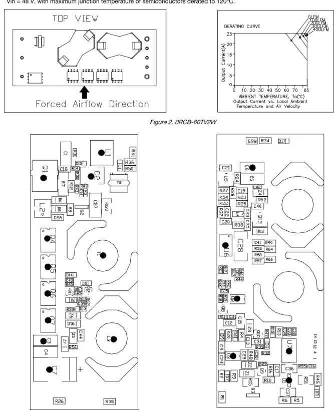
Figure 1. 0RCB-60TV2W
]
[
1
_
_
k
req
Vo
Vo
req
Vo
Rtrimdown
k
req
Vo
Vo
req
Vo
Rtrimup
1
_
_
%
100
_
Vo
Vo
req
Vo
delta
Module
Sense(+)
Trim
Sense(-)
Rtrimdown
Module
Sense(+)
Trim
Sense(-)
Rtrimup
Efficient Curve66%
68%
70%
72%
74%
76%
78%
80%
82%
84%
86%
88%
5
10
15
20
25
Output Current (A)
E
ffi
ci
en
t
38.4 V 48 V 60 V 72 VAsia-Pacific +86 755 298 85888
Europe, Middle East +353 61 225 977
North America +1 408 785 5200 © 2018 Bel Power Solutions & Protection Rev. A1 Figure 2. 0RCB-60TV2W
Material flammability: UL94V-0 Electromagnetic Compatibility EMC
1. Electric field IEC801-3(1984), IEC1000-4-3 2. Fast transient/burst IEC801-4(1988), IEC1000-4-4 Input RFI level conducted and radiated (subject to test by customer)
Compliance to EN55022 class A (both peak and average) with the following inductive and capacitive filter.
C1=3.3 µF /100 V; C2=C3= 47 µF/100 V; C4=C5=1000 pF/250 Volt; T1=3 mH
Conv.positive
input
Conv.negative
input
C1 C2 C3
T1
T1
+Vin
-Vin
C4
C5
-20 0 20 40 60 80
Level [dBµV]
150k 300k 500k 1M 2M 3M 4M 6M 10M 30M Frequency [Hz]
+
+
+ + +
+
x
x x x
x
x
x xMES 05-1012-15L_fin QP
+ +MES 05-1012-15L_fin AV MES 05-1012-15L_pre PK MES 05-1012-15L_pre AV
Asia-Pacific +86 755 298 85888
Europe, Middle East +353 61 225 977
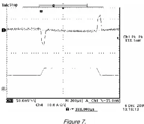
North America +1 408 785 5200 © 2018 Bel Power Solutions & Protection Rev. A1 Figure 7.
NOTE: Dynamic load transient at Vin = 48 V, Ta = 25 °C, Io = (50%~75%~50%) Ionom, di/dt=0.1 A/µs.
Figure 8. Vin = 38.4 V and Iout = 25 A Figure 9. Vin = 48 V and Iout = 25 A
C1=10 µF tantalum; C2=1 µF ceramic; R=50 ohm; C=220 nF Figure 9. Vin = 72 V and Iout = 25 A
NOTE: The module doesn't guarantee at least 0.7 mm as clearance distance on bottom side. This issue should be considered if any copper traces are on the top side of the user's board.
NOTES: 1. Pin 5 must be connected to Vout-. 2. Leave Pin 6 open for nominal voltage. 3. Pin 7 must be connected to Vout+.
PIN NAME FUNCTION PIN SIZE
1 Vin+ Positive input voltage 0.040’’
2 On/Off
Input to turn converter on and off, referenced to Vin-
0.040’’
3 Vin- Negative input voltage 0.040’’
4 Vout- Negative output voltage 0.062’’
5 Sense- Negative remote sense 0.040’’
6 Trim Output voltage trim 0.040’’
7 Sense+ Positive output voltage 0.040’’
8 Vout+ Positive output voltage 0.062’’
NOTE: This module is recommended and compatible with Pb-Free Wave Soldering and must be soldered using a peak solder temperature of no more than 260 ºC for less than 5 seconds.
NOTE:
1) All Pins: Material - Copper Alloy;
Finish – 3 micro inches minimum Gold over 50 micro inches minimum Nickel plate. 2) Undimensioned components are shown for visual reference only.
Asia-Pacific +86 755 298 85888
Europe, Middle East +353 61 225 977
North America +1 408 785 5200 © 2018 Bel Power Solutions & Protection Rev. A1 NUCLEAR AND MEDICAL APPLICATIONS - Products are not designed or intended for use as critical components in life support systems, equipment used in hazardous environments, or nuclear control systems.
TECHNICAL REVISIONS - The appearance of products, including safety agency certifications pictured on labels, may change depending on the date manufactured. Specifications are subject to change without notice.
Control
Isolated Feedback
Control 2
3
4
7
5 6 Choke
Capacitor Resistor