Application of Mobile 1P to Tactical Mobile Internetworking
Charles Graff Michael Bereschinsky Mitesh Patel US Army CECOM, Fort Monmouth, NJ
Li Fung Chang BeHcore331 Newman Springs Rd.
Red Bank, NJ 07701 Abstract
Mobile Internetworking Protocol or Mobile 1P, proposed in the Internet Engineering Task Force (IETF), does not consider the requirements of tactical military networks, which are predominantly radio based and “on the move” with minimal fixed infrastructure. In this paper, we present a tactical Mobile 1P solution for the military architecture, specifically the Radio Access Point (RAP) network, with a focus on providing mobility and fault tolerance. Our approach, in this work, is on improving survivability by moving mobility agents to higher, less mobile and more fault tolerant echelons in the hierarchy. As a baseline approach, we propose a tactical Mobile 1P solution based on the Mobile 1P protocol proposed in the IETF using Class C address assignment. It is observed that an architecture with multiple Class C address assignment supports basic Mobile 1P operation without any modification. We propose the use of Classless Inter-Domain Routing (CIDR) to accommodate a large number of Internet addresses. It is shown that other address assignment schemes can also be applied to the military architecture without any modification to Mobile 1P. Three route optimization schemes are also described to improve the performance of datagram routing to mobile nodes.
1. Introduction
Existing Internetworking Protocols (1P) were designed for a stationary network topology. A Mobile Internetworking Protocol (Mobile 1P) [1] has been proposed in the Internet Engineering Task Force (IETF) to allow 1P nodes to change their point of attachment to the network while still maintaining continuous network connectivity. Architectures and mechanisms have been provided to route 1P datagrams to and from mobile nodes, irrespective of their location in the network. Mobile 1P does not consider the requirements of tactical military networks. Tactical networks are predominantly radio based and “on the move” with minimal fixed infrastructure. They include one or more mobile components, such as mobile hosts, mobile routers and even mobile networks. The mobile networking challenge is that protocols for next generation tactical military networks must provide mobility, interoperability, survivability, reliable multicast capability and guaranteed quality of service. In this paper, a tactical Mobile 1P solution for the military architecture is presented with a focus on providing mobility and fault tolerance.
In tactical military networks, nodes located in the lower echelons are highly mobile and they require mobility support from the network. Placing mobility agents in the same network as the mobile nodes they serve, makes them highly mobile and vulnerable to attack. Our focus, in this work, is on improving
survivability by moving mobility agents to higher, less mobile and more fault tolerant echelons. As a baseline approach, we propose a tactical Mobile 1P solution based on the Mobile 1P protocol proposed in the IETF. We discuss the solution for different address assignment schemes, focusing on the use of Class C addresses. Classless Inter-Domain Routing (CIDR) ensures that the required number of mobile nodes can be supported in the military hierarchy with unsubnetted Class C address assignment. We show that the IETF Mobile 1P protocol need not be modified for the tactical military architecture. We also note that Mobile 1P operation is inefficient for datagram routing since it requires all datagrarns addressed to mobile nodes to be tunneled through the mobile’s home network. A route optimization protocol has been proposed in the IETF [3] that avoids triangle routing. In this paper, we discuss the IETF proposal and other optimization schemes tailored to fit the hierarchical military architecture.
1.1 Outline
In this section, we provide a brief overview of the military architecture, with particular emphasis on the lower echelons. Mobile 1P operation with mobile routerslnetworks and its limitations when applied to tactical military networks are discussed in Section 2. In Section 3, a tactical Mobile 1P solution for class C address assignment with CIDR is described. Class B and multiple Class C address assignment schemes are also discussed for tactical military architectures. A description of various optimization protocols to improve datagram routing and registration is presented in Section 4. A discussion of the Tactical Mobile 1P solution is provided in Section 5, followed by a summary in section 6.
1.2 Overview of the military architecture
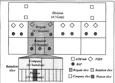
The tactical military architecture [4] is a hierarchical arrangement of mobile components. The degree of mobility varies with the echelon and the distance from the front, A division slice is illustrated in Figure 1. For illustration, we consider the Radio Access Point (RAP) network.
Asynchronous Transfer Mode (ATM) hubs, Future Small Extension Nodes (FSEN), Radio Access Points (RAP) and Unmanned Aerial Vehicles (UAV) are the major switching network elements in the military architecture. Both ATM hub switches and FSENS support Personal Communication Services (PCS) and Wireless LAN subscriber access. A RAP interconnects the army’s lower echelon radio, legacy, ATM and N-ISDN communication systems. [t utilizes ATM as the dominant switching technology and 1P as the routing technology. RAPs are highly mobiIe and must support “on the move”
communication with mobile TCP/IP and multimedia hosts. FSENS and ATM hubs are static RAPs, in that they are not as mobile as the brigade or battalion RAPs. A brigade slice has a minimum of 5 RAPs (10 proposed for the future, to provide redundancy), of which 3 are located in each of the battalions. The brigade network is considered to be the RAP network and it will be the focus of this work.
—
❑
•1Division
•1 (4/ cop)
❑
Batmlim] ‘j/ba’
I kompan) ttalio slice
Figure 1: Tactical military network - A division slice 1P data communication is expected to follow the hierarchical structure of the military architecture. While the command structure may not change very frequently, it may be necessary, as a result of battle to merge and reconstitute sections of the hierarchy, Platoons may align with another Company, or companies may change battalions. In these circumstances, the physical connectivity, and hence the communication path, will change. Users in the brigade and below are expected to be highly mobile. During battle, most of the traffic will be localized within the brigade. Communication with the higher levels is expected to be higher, before and after battle. Another example of the need to implement Mobile 1P in this otherwise structured environment is the possibility that an aerial vehicle, such as a helicopter, might download information into each battalion net while uploading other information to pass onto the higher echelons. In the next section, we will discuss the operation of Mobile 1P with mobile hosts, routers and networks.
2.Support for Mobile Routers in Mobile 1P and Its Limitations
2.1 Support for Mobile Routers in Mobile 1P
The IETF Mobile 1P proposal [1] includes support for mobile hosts (MH), mobile routers and mobile networks. Mobility scenarios differ in the way a mobile host moves with respect to its agent. For example, a host may be attached to a mobile network and it may move along with the network, A
router/agent in the mobile network provides connectivity to hosts
in that network. Hosts connected to this network, served by a mobile router, may themselves be fixed or mobile. A tank or a helicopter with 1P hosts is an example of such a mobile network.
Another scenario is the case when a mobile host is not attached to a mobile network, and the mobile host and the mobile agent, that serves it, move independent of each other. The IETF Mobile 1P supports mobile routers or mobile networks via the use of hierarchical registrations (e.g. MH registers to HA, HA registers to its home network , etc.) and recursive encapsulationhunneling to deliver datagram to the mobile host..
The Mobile 1P protocol [1] also allows mobile nodes to function without foreign agent (FA) support invisited networks. In the absence of a FA in the visited network, a mobile node should be capable of acquiring a care of address (COA) and the identity of a default router through external means such as Dynamic Host Configuration Protocol (DHCP). It should also be capable of detecting movement through link layer mechanisms. Mobile nodes should also be capable of encapsulating and decapsulating datagrams, For operation without FA’s, recursive encapsulation is not required. The number of hops traversed by datagrams and registration messages is also minimized, reducing the protocol overhead. However, functionality at the mobile nodes increases, as they have to do encapsulation and decapsulation of datagrams. In addition, not all visited networks may allow unaccounted access to mobile nodes as FA’s provide a means to account and authorize access to the network.
2.2. Limitations of Mobile IP
Mobile IPv4, without any modifications, can be used to support mobile hosts and mobile routers via multiple registrations and recursive encapsulation. However, it is also observed that triangle routing results in recursive andlor successive encapsulation for datagrann delivery through mobile routers. Encapsulation is a protocol overhead, especially when one or more links in the path are wireless. Unlike the wired network, the wireless network is low-bandwidth and prone to interference, link loss and failure. The route optimization protocol eliminates some performance issues with recursive encapsulation. Operation without FA’s also minimizes the protocol overhead while introducing more complexity at the mobile nodes. To ensure a highly survivable operation, where failure is more of a norm rather than a rare event, it is necessary to delineate the loss-prone wireless system from the wired network elements.
The IETF Mobile 1P protocol can be applied to the tactical military architecture by placing (Homo Agent) HA’s in the lower echelons, such as the platoon or Company. A HA serves mobile nodes in that network and all nodes are said to be at home. A disadvantage of this scheme is that nodes in the lower echelons are more mobile, Placing mobility agents in the lower echelons, closer to the front makes them highly mobile and vulnerable to attack. Furthermore, it is evident that with mobile agents that frequently move to foreign locations, recursive andlor successive encapsulation is required to deliver datagrams to hosts served by them.
A solution is to move the home agents to the higher echelons where nodes are less mobile. The HA’s will now serve all the mobile nodes under the echelon area. To ensure the operation of
Mobile 1P, a mobile node and it’s HA must share the same network prefix. Address assignment in the tactical military architecture is as yet unclear, It is not known if networks will be assigned IPv4class B addresses with subletting, multiple class C addresses or a single class C address without subnetting. In the following section, we describe the operation of the Mobile 1P protocol by locating the home agents in the upper echelons of the military hierarchy for different address assignment schemes.
I
25x 3 nets= 75 hosts) (2 battalions)75+ 50X 4 =275
Brigade 50 975 (I[f brigade 1950
50X3=150 is the home (2 brigades) 150+275x3= 975 network)
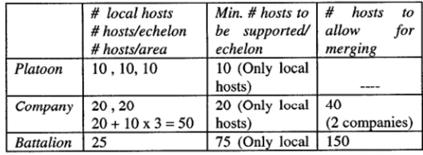
Table 1 describes the minimum number of hosts that need to be supported by each echelon network. If the brigade network is the home network, i.e. HA’s are placed in the brigade, the brigade 3. Tactical Mobile 1P solutions based on address assignment
One of the key requirements for applying the IETF Mobile 1P solution to the army architecture is to locate the mobility agents, specifically the home agent (HA), away from the lower echelons, and hence away from the highly mobile nodes it serves. Although the HA functionality can be placed in any level in the hierarchy, for the purposes of discussion, let us assume that it is located in the brigade network - in a brigade RAP. Multiple HA’s may also be deployed for survivability and load balancing reasons. It is estimated that a brigade area will need to support at least a 1000 1P hosts. The echelon with the HA becomes the home network for the mobile nodes under that echelon. If the brigade network is the home network for the mobile nodes in the brigade area, the nodes share the same network prefix as their serving HA. Address assignment mechanisms determine if the home network can support both the local hosts within the home network and the mobile nodes in the echelon area.
It is as yet unclear what address assignment will be employed in the tactical military architecture. It is not known if networks will be assigned IPv4 class B addresses with subnetting, multiple class C addresses or a single class C address without subnetting. In this section, we show that the IETF Mobile 1P protocol can be applied to tactical military architectures, irrespective of the address assignment scheme chosen. We, first, evaluate the number of hosts that need to be supported and hence the number of addresses required per network.
3.1 Number of hosts to be supported
A platoon network is expected to support 5-10 hosts that are local to the echelon. A Company network is expected to support about 20 local hosts. Brigade and battalion echelons consists of several local networks, reserved for such specialized functions as command and intelligence. A local battalion network is expected to support about 25 hosts, while a local brigade network supports about 50 hosts. We assume that brigade and battalion echelons have 3 networks each.
Table 1: Number of hosts to be supported in the echelons
# local hosts Min. # hosts to # hosts to
#hosts/echelon be supported allow for
# hosts/area echelon merging
Platoon 10, 10, 10 10 (Only local
hosts)
----Company 20,20 20 (Only local 40
2O+1OX3=5O hosts) (2 companies)
Battalion 25 75 (Only local 150
network must support a minimum of 975 hosts, which includes hosts local to the brigade echelon and all mobile nodes in the brigade area. All other echelons below the brigade support only the local hosts.
In order to allow for merge and reconstitution, address assignment for each echelon should be able to accommodate more addresses. For example, a Company network may decide to merge with a neighboring Company and reconstitute. A Company must, thus, be able to support hosts local to both companies. To allow two brigades to merge, a brigade network must be capable of supporting hosts local to both brigades and mobile nodes under both brigades.
3.2 Tactical Mobile 1P solution using CIDR
If each network in the military architecture is assigned a single unsubnetted Class C address, the network address space can support upto 256 addresses, which is not large enough to support the hosts local to the brigade echelon and all the mobile nodes in the brigade area. Classless Inter-Domain Routing (CIDR) address assignment [6 - 9] allows a brigade network to be assigned a block of addresses large enough to support all 1P hosts within a brigade.
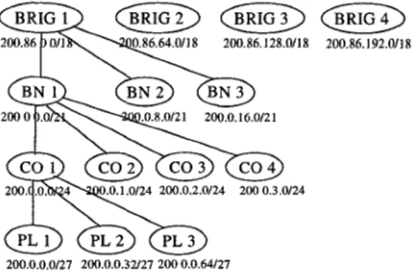
CIDR is an addressing scheme for the Internet that allows for more efficient allocation of the 1P address space than the class-based class A, B and C address scheme. CIDR address assignment is in blocks of addresses that can be assigned to networks as small as 32 hosts, up to networks with over 520,000 hosts. Network prefixes are no longer limited to 8, 16 or 24 bits. A CIDR address includes the standard 1P address and information on how many bits are used for the network prefix, which can be varied from 13 to 27 bits. For example, a CIDR address, 200.0.0.0/1 8, indicates that the first 18 bits identify the network and the remaining 14 bits identify a particular host. Using CIDR address assignment, a brigade network can be assigned a block of addresses equivalent to 64 Class C addresses, with a CIDR block prefix of 18 bits. The first 18 bits of the Internet address identify a unique brigade network. An address space with a network prefix of 18 bits can support 16,384 addresses.
From Table 1, a platoon network must support upto 10 hosts, which means a CIDR network address of 27 network bits can be assigned to it. A CIDR platoon network address can then support upto 32 addresses. A Company network must support upto 40 hosts and also allow upto 6 platoons/Company with merge and
reconstitution. A Company is assigned a network address with 24
network prefix bits that supports upto 8 platoons under it. Similarly a battalion network is assigned a network address with
21 bits prefix that accommodates upto 8 companies per battalion. If a brigade echelon is engineered to support upto 6 battalions with merge and reconstitution, it is assigned a network address with an 18-bit prefix.
?ai2’
BRIG 1 @@@iED @@o200.86 0/1 0.86.64.0/18 200,86, 128.0/18 200.86.192.0/18
BN 1 BN 2 BN 3
2000 .0 .0.8.0/21 200.0, 16,0/21
%
cO1
GZR@m@3
200, .0, 4 .0.1,0/24 200,0.2.0/24 200 0.3.0/24&
@a
200.0.0,0/27 200,0,0.32/27 200 0.0.64/27
Figure 2: An example of CIDR address assignment
Figure 2 illustrates an example of CIDR address assignment for the brigade area. Addresses have been chosen based on the criteria described in [9]. Each network is considered to be an administrative domain. We assume that the brigade network is home to all mobile nodes under a brigade. Mobile nodes located in echelons lower than the home (brigade) network are said to be in foreign networks. A datagram addressed to a mobile node’s home address will be intercepted by the node’s HA, encapsulated and tunneled to the mobile in the foreign network. Optimizations that improve on basic Mobile 1P operation are described in the next section.
CIDR does not change the Internet routing and addressing architectures. Our solution using CIDR does not require any modifications to the basic Mobile 1P protocol, except to introduce route optimization. Also, since CIDR was developed as an interim solution, transition to a more long-term solution, such as IPng, will not be affected by its deployment. CIDR requires that inter-domain routing protocols in use be capable of handling reachability information advertised by CIDR domains. Border Gateway Protocol-4 (BGP-4) and C)pen Shortest Path First-2 (OSPF-2) protocols, used by routers in the RAP architecture, meet this requirement because they carry network routes with associated masks, without relying solely on class-based, fixed network prefixes. CIDR does not require that all the domains be converted to use CIDR. Echelons above the brigade, such as the division and Corps, need not conform to CIDR address assignment, to conserve address space. For example, a brigade network is assigned an 18 bit network prefix that can support upto 16384 addresses. Since the number of hosts in the Corps and division echelon networks is only 12000, CIDR address assignment would waste addresses. Although CIDR will still provide connectivity to all domains, the optimality of routes to non-CIDR domains may be impacted. The applicability statement [6] does recommend that to minimize routing table expansion, backbone and transit Internet domains implement CIDR.
3.3 Other address assignment schemes
Since, it is not yet clear what address assignment scheme will be adopted in the military architecture, we will also discuss the viability of the IETF Mobile 1P solution for other address assignments.
If all networks are assigned subnetted Class B addresses, a class B network address space will accommodate the hosts local to the brigade and the mobile hosts in the brigade area that are served by one or more HA’s in the brigade echelon. Each brigade network is expected to support atleast 50 hosts. The local brigade networks can be assigned subnetted Class B addresses with 6 bits for the host ID that can support upto 64 addresses. A brigade area is expected to support about 1000 hosts, i.e. the mobile net should have enough addresses to support all the mobile nodes in the brigade area. In addition, to allow for merge and reconstitution, the brigade echelon should be able to accommodate hosts supported by one other brigade, for a total of 2000 1P addresses. However, merge and reconstitution can be accomplished without address re-assignment for Class B address assignment. When two brigades merge, networks within the merging brigade are incorporated into the reconstituted brigade echelon. Propagation of routing information ensures that 1P routing will correctly reflect the change in the network. The battalion echelon also has local networks and each network is expected to support approximately 25 hosts. Addresses can be assigned such that a battalion network address can support upto 32 addresses. Company and the platoon echelons do not have multiple local nets. A Company net is expected to support about 20 hosts and a platoon network may support 5-10 hosts. Companies and battalions can also merge by incorporating the new networks into the reconstituted echelon without address re-assignment.
Alternatively, instead of subnetted Class B addresses, networks can be assigned one or more Class C addresses. The Mobile 1P protocol can still be applied to the military architecture for a tactical Mobile 1P solution. Local brigade networks dedicated to intelligence, command and other specialized functions are all assigned subnetted Class C addresses. Each network is expected to support atleast 50 hosts and address assignment allows 6 host ID bits to support upto 64 addresses. If HA’s are placed in the brigade network, the brigade echelon is expected to support about a 1000 hosts. A single Class C address provides 8 bits for the host ID and can accommodate only 256 addresses. As a result, each local network must be assigned a separate Class C network address. It is advisable to isolate the mobile node networks from other brigade networks for loading and security reasons. Address assignment for the lower and higher echelons can be similarly derived. Merging and reconstitution can be accomplished in a manner similar to that described for Class B addresses without address re-assignment.
4. Route optimization
Basic Mobile 1P operation is inefficient when most of the communication is localized within a hierarchy and the home agent is not located in the same echelon. For example, communication between nodes within the same platoon would
require all datagrams to be routed to the home network, encapsulated by the HA and routed back to the destination mobile. Route optimization protocols can be employed to improve the performance of datagram routing to mobile nodes. 4.1 IETF route optimization
The route optimization protocol [3], proposed in the IETF, enhances the IETF Mobile 1P protocol [1] by avoiding sub-optimal routing of 1P datagrams through the HA. Basic mobile 1P does not provide mechanisms to reliably notify previous FA’s of the new location of the MH after a MH moves. It relies on registration expiry at the foreign agents to expire out old bindings. Route optimization addresses the issue of loss of data due to mobile movement or registration expiry.
All 1P nodes are not expected to implement route optimization. If a node is unable to process optimization protocol packets, it defaults to basic Mobile 1P operation. 1P nodes that implement route optimization maintain a cache of mobility bindings for mobile nodes, called a binding cache. If a CH is unaware the destination host is mobile, it sends the 1P datagram addressed to the MH’s permanent 1P address. The MH’s HA intercepts the packet if the MH is away from home. The HA tunnels the packet to the MH at it’s foreign location. Simultaneously, the HA sends the binding information of the MH to the CH. If the CH implements route optimization, it caches the association between the MH’s home address and it’s COA in its binding table. All future datagrams from the CH to the MH are sent directly to the MH in its foreign network.
With mobile agents, route optimization offers significant advantages as it avoids recursive andlor successive encapsulation, Datagram routing through multiple home and foreign agents is eliminated when the CH is informed of the mobile node’s location in the network.
4.2 Route optimization with distn”buted databases
Based on our assumption that, in hierarchical networks, most 1P data communication follows a hierarchical path and is localized within a hierarchy, we propose an extension to the route optimization protocol using distributed databases to maintain mobility bindings. The purpose is to localize traffic within a hierarchy. In the lower levels of the hierarchy, the databases can maintain mobility bindings for visiting mobile nodes. Since routers are considered secure, it may be appropriate to place the databases in the routers. The databases could also be located in mobility agents. When a node sends an 1P datagram addressed to a mobile node, the packet will be routed using normal 1P routing to the mobile’s home network. With route optimization and binding databases, if intermediate routers/databases have a cached mobility binding for the mobile node and it is determined that it is not necessary to route the packet to higher layers, the router can encapsulate and redirect the datagrarn to the destination mobile. In the interests of security, the databases must not disseminate binding information to users. Binding information must be used only to forward datagrarns in flight. The HA must periodically propagate binding information for the mobiles it serves, to the databases that fall in the routed path to the mobile.
The advantage of this scheme is that mobile nodes can be less complex, since they do not implement route optimization. By setting a bit in the mobile 1P header, examination of all packets by all routers on the path to the MH in the foreign network can be avoided.
4.3 Route optimization
with disti”buted databases and no
tunneling
This scheme is an extension of the previous approach with distributed databases. In this optimization scheme, when a packet arrives at a router, and the router determines that it has a binding, it forwards the original datagram to the next hop towards the foreign network where the MH is located. The router does not change the destination address in the original datagram. It does not encapsulate the packet either. The router at the next hop checks its database and forwards the packet towards the MH in the visited network.
This scheme does not increase the size of the datagram by encapsulation, which is beneficial if one or more links in the path to the MH are wireless or if the agents are mobile. However, all routers must examine all packets that flow through it to determine if they have a binding for the destination 1P address. It may be beneficial to maintain the binding databases only in the lower echelons, say only at the battalion and/or Company levels, especially if data traffic is terminated at these levels. This solution will minimize the delay in datagram delivery as fewer databases are accessed and tunneling through the HA is avoided. 4.4 Route optimization with adaptive location management
An adaptive location management strategy has been proposed in [10] that relies on the key observation that the set of nodes that a given mobile node communicates most frequently with is small. Since communication in military networks is highly localized, this locality property can be exploited to reduce the costs of location management. Location management involves two costs - the cost of tunneling the packet through the HA along the triangular, non-optimal route and the cost of updating a corresponding node with the current location of the mobile each time the mobile moves. The proposed scheme uses an on-line algorithm to reduce the overall costs of location management. It evaluates whether it is more beneficial to allow a corresponding node to tunnel packets through the HA each time it sets up a connection to the mobile, or simply update the correspondent node each time the mobile moves. This scheme can be directly applied to the military network since a strong locality property exists in military communication. For communication between nodes in the same echelon, the mobile node may choose to inform the correspondent node of its foreign location in the network to avoid triangle routing through a mobile HA in some higher echelon.
In summary, any of the above route optimization schemes can be employed to improve the efficiency of datagram routing to mobile nodes in the tactical military architecture. Further study is required in this area.
5. Discussion
5.1 Use of home agents
Our solution locates the HAs in the higher echelons, away from the front, to provide a survivable architecture. Introducing multiple HAs in the home network will further improve the survivability of the operation. The IETF Mobile 1P protocol specification [1] does not specifically detail operation with multiple HAs. However for fault tolerance, tactical mobile interworking will require support for multiple HAs in the architecture. A possible solution is that while multiple HAs can be located in the home network, only one HA actively processes mobile registration messages and implements datagram tunneling. The active HA keeps other home agents in the network informed of its current state, to ensure that service is not disrupted in the event of a breakdown. Redundancy will ensure that all HAs have the list of mobile nodes being served and the current mobility bindings. Switching operations from a “downed” agent to a previously passive agent requires further study. One option is for the agents to identify the “downing” of an agent by monitoring the link connecting them. Breakdown of the link or route to an active agent might indicate that the agent is no longer available to provide services to mobile nodes. 5.2 Use of foreign agents
The Mobile 1P protocol requires that the FAs have link layer connectivity with the mobile nodes they serve. This raises survivability issues since the FA must then be placed close to the mobile nodes in the lower echelons of the hierarchy. It might be more beneficial to allow mobile nodes to function without FAs in the visited networks. The only requirement is that the mobile nodes be capable of obtaining care of addresses through DHCP or other means, and encapsulate and decapsulate datagrams. Alternatively, multiple FAs may be placed in the networks to provide redundancy. Higher layers in the military architecture that are less vulnerable to attack may have FAs in their networks to provide support to mobile nodes.
5.3 Autoconjiguration
A key requirement for mobile nodes will be their ability to automatically configure themselves with host and network-specific configuration parameters. In the absence of FAs in visited networks, mobile nodes should be capable of obtaining care of addresses. Autoconfiguration mechanisms such as Dynamic Host Configuration Protocol or DHCP [2] have been proposed in the IETF, where DHCP servers allocate network addresses and pass configuration parameters to hosts.
6. Sununary
A tactical Mobile 1P solution for the military architecture is presented with a focus on providing mobility and fault tolerance. Key idea of our solution is that placing mobility agents in the same network as the mobile nodes they serve, makes them highly mobile and vulnerable to attack. Moving mobility agents to higher, less mobile and more fault tolerant echelons can improve survivability. Mobile nodes in the lower echelons will always be in a foreign network when the home agents serving them are located in the higher echelons. We have shown that the IETF Mobile 1P protocol can be applied to
tactical military architectures, irrespective of the address assignment scheme chosen. If networks are assigned a single unsubnetted Class C address and the home network is defined by a higher echelon, the address space is insufficient to support all the mobile nodes in the home network. We propose the use of CIDR for address assignment in the hierarchical military architecture. The CIDR solution is the application of existing technology to enable mobile internetworking in the tactical military architecture. It is a baseline approach that applies the IETF Mobile 1P protocol, without any modification, to the military architecture. Three route optimization schemes are also described to improve the performance of datagram routing to mobile nodes.
8. References
[1] C. Perkins, “1P Mobility Support,” RFC 2002, IETF, October 1996.
[2] R.Droms, “Dynamic Host Configuration Protocol (DHCP)”, RFC 1541, IETF, October 1993.
[3] D.B.Johnson, C.Perkins, “Route Optimization in Mobile 1P,” draft-ietf-mobileip-optim-05.txt, Internet draft of the Mobile-IP working group, IETF, November 1996, Work in progress. [4] Charles Graff, “Future Network Architecture for Tactical Army Networks,” IEEE talk, Viewgraphs available from
[email protected]. army. roil.
[5] H-W.Braun, P. S.Ford, Y.Rekhter, “CIDR and the Evolution
of the Internet Protocol,” Proceedings of INET’93, 1993. [6] R.Hinden, “Applicability Statement for the Implementation of Classless Inter-Domain Routing (CIDR),” RFC 1517, IETF, September 1993.
[7] Y.Rekhter, T.Li, “An Architecture for 1P Address Allocation with CIDR,” RFC 1518, IETF, September 1993.
[8] V.Fuller, T.Li, J.Yu, K.Varadhan, “Classless Inter-Domain Routing (CIDR): An Address Assignment and Aggregation Strategy,” RFC 1519, IETF, September 1993.
[9] E. Gerich, “Guidelines for Management of 1P Address Space,” RFC 1466, IETF, May 1993.
[10] S.Rajagopalan, B.R.Badrinath, “An Adaptive Location Management Strategy for Mobile 1P,” Proceedings of MOBICOM, pp. 170-180, November 1995.