7
Innovative Research in Engineering Sciences Vol 2(3), 7-17 (2016)
Journal of Innovative research in engineering sciences
Journal homepage :
www.joires.com
The load-sharing
control in parallel inverters in a distributed generation network in the presence of
unbalanced loads using voltage frequency drop controller
Peyman Torshizi1*, Behfar Farzaneh2
1,2. Islamic Azad University of Majlesi , Isfahan, Iran
.
Abstract: In this article, load-sharing control in parallel inverters in a distributed generation network in the presence of unbalanced loads using voltage frequency loss controller has been investigated. In this paper, the issue of active and reactive power divide in micro-grid parallel inverters has examined at different situations of system impedance.
In order to achieve the appropriate power balance between parallel inverters and minimize the eddy current in the presence of line various impedance, a drop controller has been suggested. In this controller, the dependency between active and reactive power relations in the presence of complex impedance in parallel system inverters has determined simple and distinct.
In addition, a virtual complex impedance loop in drop controller has been intended, so that eddy current to be minimize due to the lack of impedance mismatch in the parallel inverters system. However, there is no need to measure inverter output current for power division control.
Therefore, this method has caused of a structure with complexity and less cost in which the number of measurements has decreased from three to two. The simulations results show that compared with other methods of load sharing, the used controller has accurate
power division and effective dynamic performance and is compatible with various situation of the line impedance
Kay words:Distributed generation resources, Parallel inverters, Load-sharing, Eddy current, Drop control, Virtual impedance
1. Introduction
Naturally, power systems have complex structures and multivariate. The objective of eddy current control and load frequency is to maintain zero errors of steady state in an interconnected multi- area a power system.
Several control strategies have been employed to achieve this purpose that the current voltage control method is very interesting, because this method was only locally based on the measured inverter information
and is not affiliated to internal communication signals between the inverters and then it constituents a
distributed and independent system.
While the eddy current generated by two inverters were undesirable which for its improve, we use a fuzzy controller alongside of the above controller.
The presented major/ minor automatic control in [1]
has been designed in this way the unit with the largest output real power to be implemented as the major unit of real power and to determine the reference frequency,
so that the inverters are forced to be operated as the
minor units.
Reactive power regulation has done also in the same way, then the module with greatest output reactive power to be implemented as the major unit of reactive power and to regulate the reference voltage amplitude. In [2] this paper focus on the performance and independent micro-grids behavior under different conditions and situations.
However, two main control strategy have been investigated, the single main function is used when there is not the main power source, a voltage source inverter (VSI) is applied as voltage reference. All other inverters can operate in PQ modes. The function with the several
main unit is operated when more than one inverter to be
acted as a VSI, the other Inverters may also be present.
In [3] circular chain control strategy (C3) is proposed, all modules have the identical circuit structure, and each module contains an inner current loop and an outer voltage loop. By using of C3 approach, all modules are related to circular chain, and each module has an inner current control loop that to follow its previous module self-current towards of equal current distribution. This approach is used often for UPS
application and automatic voltage regulation (AVR).
In [4] this paper is presented a solution to the problem of harmonic eddy current noise due to asynchronous PW caused by reduces the load sharing accuracy. It is done using of a digital control algorithm for parallel three-phase inverters. Digital voltage controller, has a current control with high-speed as
minor loop, so low voltage distortion provides even for non-linear loads. The output current each UPS module
has controlled for equal division of the total load current and voltage reference of each inverter is controlled in order to balance the load current.
In [5] this paper focuses on the development of the solution to the effect of DC offset between parallel inverters and its impact on the eddy currents.
In [6] this paper provides a control method for operation of two or more single phase inverter module
in parallel mode without any additional connection. In
Contains an inner current loop and an outer voltage loop. This method is similar to the concept of traditional
voltage / frequency by using of major voltage drop and frequency that allows to all independent inverters which
the load is divided according to their capacity. However, this article considers only inductive lines.
In [7], reverse drop equations have used for the inverter control. The inverter is able works in parallel with a constant voltage - constant frequency, as well as
with other inverters or in standalone mode. The different power sources can divide the load even under unbalanced conditions.
In [8] an interesting independent load sharing technique has provided for parallel three-phase voltage source converters. This article focuses on improving conventional frequency drop method for the real power
division and developing of a new reactive power division method. So, the improved frequency drop method of VSC phase angle to calculate and regulate instead of its frequency.
This method allows to operator that can to regulate
the real power division controller in order to achieve optimal system response without compromise with
frequency regulation which this issue is conducted by adding an integral gain to real power control.
In [9], the authors consider that large DC currents may pass between the different inverters that usually are ignored, because the only passing AC current to be account through control schemes. However, this phenomenon only if we have the DC voltage offset significant difference between the inverters, can take place that often it is not notable, because these errors are generated by the sensors and are very small.
In [10] a research which is called as contrast drop control (Active power drop/ Voltage and reactive power) has been conducted. The focus of this research is on the different drop functions requirement for various types of network. In this paper, it proves that for high voltage networks (Dominant inductive lines) can be used ordinary horizontal functions.
For low-voltage networks (Dominant resistive lines), we should be used the contrast horizontal functions, but ordinary horizontal functions are useful because they provides connection possibility to higher voltage levels as well as the power division with the battalion generators. A micro-grid control method in [11] is introduced and employed.
Micro-grid has two critical components, which are called as follow: Static key and Mini-source. Static key has this ability that to separate micro-grid independently from disturbances such as errors, the events of 1547 IEEE, or power quality events. After separation, reconnect micro-grid independently is conducted after the resolve of the event. This synchronization is obtained by using the difference between the islanded network and the major power grid ensuring of transient performance without need to frequency adaption and phase angle at the connection point.
Each micro-source can be controlled using a power horizontal controller versus power integrated frequency in an islanded micro-grid. This frequency drop also ensures that the micro-grid frequency is isolated that makes easy its reconnect to the network. The mentioned
micro-source control method has been shown in Figure 2-10.
The authors [12] have provided a method for parallel inverters control using horizontal division method in a standalone AC system. The method of a PI regulator offers the regulation points to determine the angle and a generator flux. Micro-grid power system model in MATLAB / SIMULINK have been simulated. The system dynamic response has been investigated under the different impedance load conditions especially the motor loads.
In [13], a proposed method for the used inverters in distributed generation systems in order to improve the source converters horizontal functions is in such a way that the normal drop functions have applied in steady mode and contrast functions in the transients. In [13-14] the authors focus on the UPS parallel inverters transient behavior. They claim that the oscillatory phenomenon and damping phase shift between parallel inverters can cause instability, and a large transient eddy current which may overload and damage to parallel inverters.
The planned gain by fuzzy controller in fact is a used control design technique for nonlinear systems. In this
method, the control parameters can be changed very quickly, because the estimation of parameters is not required. This work seems easier to realize of automatic
regulation or adaption of control parameters. However, transient response can lead to unsteady mode, due to rapid changes in system parameters. In addition, to obtain an accurate model of linear fixed- time is
impossible in the variables performance points.
In [15] The current inverter feeds the resulting voltage difference between a reference voltage source AC voltage and impedance network on a virtual or the real and / or imaginary is. Supply voltage AC, with a phase shift, depending on the difference between real and nominal frequency synchronous grid reference or the network.
The author [16] on the problem inverter output impedance is very small (such as those that employ resonance controllers) directly via a cable or parallel non-zero impedance discusses.
The authors [17] are introduced a quick control loops that regulates output impedance of closed-loop inverters in order to ensure self-behavior with aim of the appropriate division harmonic current content.
This paper presents a small-signal analysis for parallel inverters in independent AC power systems.
The control approaches have inherent compromise between the voltage regulator and the power division.
The proposed signal injection technique in [18] was not dependent to system parameters and can be divide reactive power even if the VSCs do not have completely
identical output inductors, which by injecting a 50 Hz signal and use of it, is conducted as a means for common load-sharing with other the VSCs network. However, the
required circuit for small changes measuring of output real power caused by the injection signal adds to the control complexity.
In [19] a proposed control approach is used the data communication signals with low bandwidth among each
distributed sources systems that can be transmitted from the connection to network to the islanded performance
without probable problems for critical loads.
In the present study, the load-sharing control in parallel inverters in a distributed generation network in the presence of unbalanced loads by using of the voltage frequency drop controller is investigated.
In this article, the power division for parallel inverters under the terms of the pure inductive impedances, pure resistive and mixed is analyzed completely and this study shows that the power division between two parallel inverter by using the current
voltage control method and fuzzy controller at the same time has better results than current voltage control for
eddy current reduce and appropriate voltage load. The application of this research is to encourage large companies to produce their annual consumed energy as well as their surplus energy sell to smaller factories.
2. Problem Statement
With regard to the increasing distributed generation energy sources in the country, the power division between the located inverters in these systems are very important and have a special place.
In this paper, we are seeking to create an appropriate
method for power control between the located parallel inverters in a micro-grid network in the presence of variable and disrupted loads. According to the nature of the located loads in energy generation systems in terms
of resistive, inductive or mixed are not known, as well as in all hours are not fixed, and are unsteady, so this unknowns makes that cannot be used classic control methods.
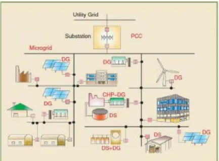
Figure (1) shows a schematic diagram of a micro-grid. Micro-grid includes a part of the electricity distribution system that is located in distribution substations downstream and various DER units and different types of end consumers are embodied the electricity energy with heat.
DER units include both distributed generation (DG) units and distributed storage (DS) with different capacities and characteristics. Micro- grid electrical connection point to the network, in the pass distribution low voltage transformers, to form a point of common coupling (PCC) micro grid.
In fact, micro grid is feeding a range variety of consumers, including residential complex, economic institutions, and industrial towns.
With regard to the increasing distributed generation energy sources in the country, the power division between the located inverters in these systems are very important and have a special place. In this paper, we are seeking to create an appropriate method for power control between the located parallel inverters in a micro-grid network in the presence of variable and disrupted loads. According to the nature of the located loads in energy generation systems in terms of resistive, inductive or mixed are not known, as well as in all hours are not fixed, and are unsteady, so this unknowns makes
that cannot be used classic control methods.
Figure 1. The structure of a typical micro grid including loads and dependent DER units to a distribution system.
2-1. Hypothesis
1- The parallel inverters in a Micro-grid network have power and the same work characteristics.
2- It is used two parallel inverter in the network.
3- The distributed generation source is not discussed with other network distributed generation resource and separately to be
control.
4- The inverter output impedance because of the design possibility is complex with multiple feedback.
5- The amount of resistive and inductive impedances for line is fixed.
2.2 Research Objectives
line with improve of distributed generation systems control.
2- 2-Providing a smooth path to promote of knowledge in the field of distributed generation resource.
3- Create appropriate field to obtain construct technology of high power inverters in micro-grid networks.
4- 4-Promote construct knowledge and thus the lack of many costs to enter such these systems. 5- Providing appropriate context for the
development of internal policies towards new energies.
3. Solving method
In the present paper, the active and reactive power division characteristics for parallel inverters are thoroughly analyzed under the terms of the pure inductive impedance, pure resistive and mixed. This study shows that conventional drop method cannot obtain the efficient power division about the system mixed impedance. To overcome this problem and minimize the eddy current under all conditions, is used an improved drop controller that considers the effect of complex impedance. This controller makes easy the active and reactive power relations related to the complex impedance situation. In addition, a moment virtual impedance loop is introduced in order to ensure steady state performance and transient when loads are to be shared. In addition, the need to measure the output current for power division control with its implementation is eliminated in a software process. This causes a structure with the less complexity and lower price which the number of feedback sensors to be reduced from three to two. Finally, in order to improve the controller performance during the non-linear loads- sharing, has been used of One Cycle Control (OCC) to control the parallel inverters and the results using Pulse Width Modulation (PWM) is compared. The
studies were indicated the advantage of the OCC method compared to PWM for inverters switching
in time of the non-linear loads-sharing and increases the delivery voltage quality to the load.
3.1 Power Division Theoretical Analysis
Figure (2) shows a power supply system with connected single-phase inverters multiple in parallel with load sharing through a common bus ac. Figure (3) shows a single-phase inverter equivalent circuit obtained from the venin theorem [20]. In this figure, E ∡∅ indicates the inverter open circuit voltage, I ̅_0 indicates the inverter output current, U ∡0° indicates the common bus voltage, R + indicates the inverter system impedance, which includes output impedance and line impedance, and z and θ, respectively indicates the amplitude values and its phase.
According to the equivalent circuit a parallel inverter in Figure 3, the inverter output current can be obtained as follows.
𝐼̅0=
𝐸 ∠ ∅−𝑈 ∠ 0
𝑍 ∠𝜃 =
𝐸
𝑍∠(∅ − 𝜃) − 𝑈
𝑍(−𝜃)𝑍̅ = 𝑅 + 𝑗𝑋 (1)
In addition, the injection apparent power by an inverter to common bus ac is equal to:
𝑆 = 𝑈 ̅̅̅̅𝐼𝑎̅ = 𝑃 + 𝑗𝑄 (2). Where (I_a ^.) ̅is conjugate (I_0). ̅ Using (1) and (2), active and reactive power is equal to:
𝑃 =𝑈
𝑍[(𝐸 𝑐𝑜𝑠∅ − 𝑈)𝑐𝑜𝑠𝜃 + 𝐸 𝑠𝑖𝑛𝜃 𝑠𝑖𝑛∅] (3)
𝑄 =𝑈
𝑍[(𝐸 𝑐𝑜𝑠∅ − 𝑈)𝑠𝑖𝑛𝜃 + 𝐸 𝑐𝑜𝑠𝜃 𝑠𝑖𝑛∅] (4) Suppose that θ phase difference between the inverter output voltage and the common bus voltage is too small, because the inverters at first using the locked loop module in phase (PLL) are the
synchronization, then (3) and (4) can be written as the following form:
𝑃 ≅𝑈
𝑍[(𝐸 − 𝑈)𝑐𝑜𝑠𝜃 + 𝐸 𝑠𝑖𝑛𝜃 ] (5)
𝑄 ≅𝑈
Figure 2. Feeding system with parallel inverters
Figure 3. Equivalent circuit of a parallel inverter
Now, using Figures (5) and (6), it is shown that the relationship between the output voltage and delivered power are determined by the system impedance angle of
θ. Table (1) shows active and reactive power in terms of the value of θ.
Table 1. Active and reactive power of parallel inverters with the different systems impedance
Complex impedance θ= 𝒁̅ , 𝑹 + 𝒋𝑿
Pure inductive θ= 90° , 𝒁̅= jX Pure resistive
θ= 0° , 𝒁̅= R Impedance
system
Active power
𝑃 ≅𝑈 (𝐸 − 𝑈)
𝑍
𝑃 ≅𝑈𝐸∅
𝑍
𝑃 ≅𝑈
𝑍[(𝐸 − 𝑈)𝑐𝑜𝑠𝜃 + 𝐸∅𝑠𝑖𝑛𝜃]
Reactive power
𝑄 ≅−𝑈𝐸∅
𝑍
𝑄 ≅𝑈 (𝐸 − 𝑈)
𝑍
𝑄 ≅𝑈
𝑍[(𝐸 − 𝑈)𝑠𝑖𝑛𝜃 + 𝐸∅𝑐𝑜𝑠𝜃]
4. Results
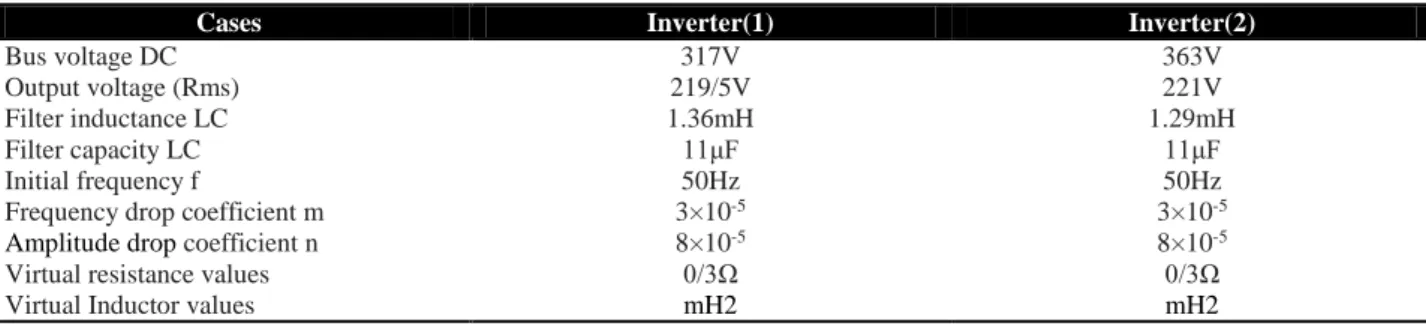
In order to evaluate the proposed controller performance, the numerous simulations have carried out in Mat lab / Simulink software and its relevance results are presented in this chapter. All parameters are listed in Table 2. The results are divided into two main parts of
inverter control with Pulse Width Modulation (PWM) method and One Cycle Control (OCC) method. In control section with PWM method, are presented the relevance results to three-phase mode and also nonlinear load feeding. In the end, the performance of the control system using OCC method and its comparison with PWM method are considered.
Table 2. Parallel inverters parameters
Inverter(2) Inverter(1)
Cases
363V 317V
Bus voltage DC
221V 219/5V
Output voltage (Rms)
1.29mH 1.36mH
Filter inductance LC
11μF 11μF
Filter capacity LC
50Hz 50Hz
Initial frequency f
3×10⁻⁵
3×10⁻⁵
Frequency drop coefficient m
8×10⁻⁵
8×10⁻⁵
Amplitude drop coefficient n
0/3Ω 0/3Ω
Virtual resistance values
mH2 mH2
Virtual Inductor values
4.1 The inverters control with PWM method and
load-sharing with three-phase inverter and
non-linear load
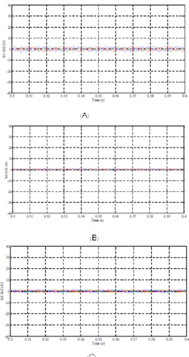
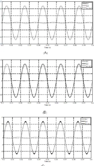
The eddy current between the two inverter for complex line impedance, inductive and resistive, respectively, are shown in Figures 4 (a) to (c) is. Figure
(5) the inverter output voltage and load current is assigned simultaneously. The voltage quality due to
injection harmonics was very low from non-linear load and has very high THD.
We'll see in Section 4.2 that through the inverters control using OCC method can be largely overcome this disadvantage and produce the voltage with better quality
that it does not affected the other available loads in the
Figure 5. Eddy current waveforms in three phases: (A) Complex line; (B) Inductive line. (C) Resistive line
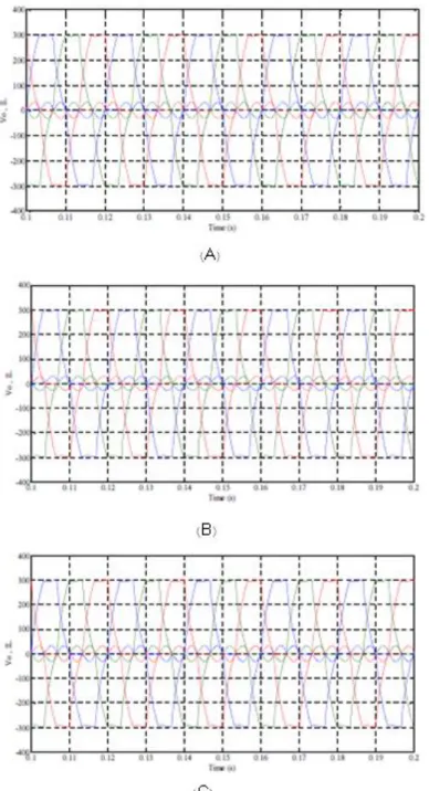
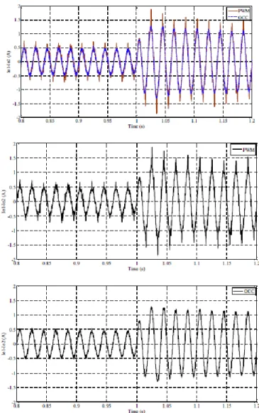
4.2 The inverters control with OCC method
In this section in order to improve the current division system performance during non-linear loads feeding, has been used one cycle control method for the inverters control. This method in addition to reduction TDH of the inverter output voltage, in terms of
Figure 6. Parallel inverters currents with ICC method; (A) Complex line; (B) Inductive line. (C) Resistive line.
Figure (7) shows inverter output voltage when is used one cycle control method. In addition, Table 3 compares inverters output voltage THD values in different modes of output impedance for both OCC and PWM method during the non-linear load feeding. As it
is observed, total harmonic distortion using one cycle control method was less than control with pulse width modulation method and in all cases is less than allowed
value of 5%
Figure 7. The inverter output voltage using OCC method during nonlinear load feeding
Table 3. Comparison THD inverter output voltage
PWM OCC
Impedance
5.27 5.7 5.17 4.26
4.62 4.43 Complex
4.2.1 The investigate of system dynamic performance
Figure (8) shows eddy current waveforms in response to load sudden increase. In this case, at the time oft=1s, the common load increases to the double amount. In order to compare, the obtained results of the OCC and PWM techniques have been presented at the same time. As it is observed, OCC method due to having faster dynamic in response to load sudden changes because of fast tracking of voltage reference waveform, has better performance and in addition to its eddy current amplitude is also smaller. Another important point is that the available eddy current between inverters in OCC techniques harmonic and less distortion. Eddy current harmonic spectrum of these two methods in order to comparison has been shown in Figure (9). Eddy
current THD has been measured in one cycle control mode equal to 3%/0. 38, but in PWM control mode equal to11%/0. 61. This issue can be considered as one
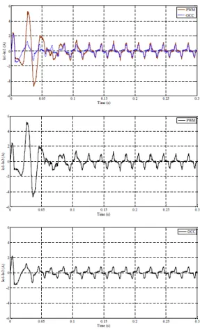
of the superiority reason of one cycle control method that shows the inverters output voltage in this method has less distortion and makes prevent the harmful harmonics injection into the system. In order to evaluate the system dynamic behavior during the time of experimental non-linear load feeding in primary moment has conducted to startup of system work that its result has been shown in Figure (10). This waveform represents the eddy current over conventional pulse width modulation method has proven and it is observed that in OCC method the initial eddy current has overshoot and less time.
Figure 9. Eddy current THD comparison; A) PWM method; B) OCC Method.
Figure 10. Eddy current waveform during startup and non-linear load feeding
Conclusion
In this paper, load-sharing control in parallel inverters in a distributed generation network in the presence of unbalanced loads were investigated using voltage-frequency drop controller. A control method for parallel inverters without need to communication signals, was presented by considering the impact of complex impedance over the power division. This controller considers all of the different modes parallel
inverters output impedance ranging from inductive, resistive or complex. For this purpose, a virtual complex impedance loop was used to minimum the eddy current
voltage inverter output during the use of one- cycle control method is reduced and prevents the entrance of non-linear load harmonic to independent system voltage. Then, a structure for active and reactive power of inverters output was used to reduce the number of measurement sensors from three to two, and also was caused the simplicity of controller structure. The used controller, in which case the inverters are feeding a common load, offers steady state performance and good dynamic response. Several simulations were performed to test the system performance which the obtained results show that the controller is able to minimize eddy current and also decrease its harmonics
References
[1]. Pei, Y. Auto-master-slave control technique of parallel inverters in distributed AC power systems and UPS, 35th Annual IEEE Power Electronics Specialists Conference, 2004.
[2]. Lopes, J. A. P., Moreira, C. L., Madureira, A. G. Defining control strategies for Micro-Grids islanded operation, IEEE Trans. Power Sys, 2006.
[3]. Wu, T. F., Chen, Y. K., Huang,Y. H. 3C strategy for inverters in parallel operation achieving an equal current distribution, IEEE Trans. Ind. Electronic, 2000.
[4]. Kim,K. H. Hyun, D. S. A high performance DSP voltage controller with PWM synchronization for parallel operation of UPS systems, 37th IEEE Power Electronics Specialists Conference, 2006.
[5]. Qinglin, Z., Zhongying, C., Weiyang, W. Improved control for parallel inverter with current-sharing control scheme, CES/IEEE 5th International Power Electronics and Motion Control Conference, 2006.
[6]. Hua, C. C., Lin, K. A. L., J. R. Parallel operation of inverters for distributed photovoltaic power supply system, IEEE Annual Power Electronics Specialists Conference.
[7]. Matthias, H., Helmut, S. Control of a three-phase inverter feeding an unbalanced load and working in parallel with other power sources, EPE-PEMC, Dubrovnik, 2002.
[8]. Sao, C. K. Lehn, P. W. Autonomous load sharing of voltage source converters, IEEE Trans. Power Del, 2005.
[9]. Xie, M., Cai, YL, K., Wang, P., Sheng, X. A novel controller for parallel operation of inverters based on decomposing of output current, Industry
Applications Conference 14th IAS Annual Meeting, 2005.
[10]. Engler, A. Applicability of droops in low voltage grids, 3rd European PV Hybrid and Mini-Grid Conference, Aix-en-Provence, France, 2006.
[11]. Lasseter, R. H. Microgrids and distributed generation, Journal of Energy Engineering, 2007.
[12]. Majumder, R. Load sharing with parallel inverters in distributed generation and power system stability, Smart Systems, Technology, Systems and Innovation, 2007.
[13]. Guerrero, J. M. Drop control method for the parallel operation of online uninterruptible power systems using resistive output impedance, Applied Power Electronics Conference and Exposition, APEC2 006, Annual IEEE, 2006.
[14]. Guerrero, J. M., Berbel, N. Matas, J. de Vicuna, L. G., Miret, J. Decentralized control for parallel operation of distributed generation inverters in microgrids using resistive output impedance, 32nd Annual Conference on IEEE Industrial Electronics, IECON 2006, Paris, France, 2006.
[15]. De Brabandere, K. Control of microgrids, IEEE Power Engineering Society General Meeting, Tampa, 2007.
[16]. Mihalache, L. Paralleling control technique with no intercommunication signals for resonant controller-based inverters, 38th IAS Annual Meeting Industry Applications Conference, 2003.
[17]. Coelho, E. A. A., Cortizo, P. C., Garcia, P. F. D. Small-signal stability for parallelconnected inverters in stand-alone AC supply systems, IEEE Trans, 2002.
[18]. Tuladhar, A. Advanced Control Techniques for Parallel Inverter Operation Without Control Interconnections, Dept of Electrical and Computer Engineering, The University of British Columbia, 2000.
[19]. Marwali, M. N. Jung, J. W. Keyhani, A. Control of distributed generation systems. Part II. Load sharing control, IEEE Trans. Power Electron, 2004.