www.ijseat.com Page 597
CONTROL OF ACTIVE AND REACTIVE POWER USING DISTRIBUTED
ENERGY SYSTEM FOR POWER GENERATION IN DISTRIBUTION
NETWORK
S Swapna Dharma, PG Student and Shaik Hussain Vali, Assistant Professor
Department of EEE, JNTUK-UCEV, Vizianagaram, A.P. India
Abstract:- At present decentralized energy sources are more beneficial than conventional centralized energy sources, distributed energy sources are decentralized energy sources. Decentralized energy sources use renewable energy sources such as small wind power, solar power, biomass, etc. In this work wind energy is used as the distributed energy source in the distribution network. Active power is generated from distributed energy source but it is unregulated as it depends on wind. D-STATCOM inverter regulates both real and reactive power with delta and modulation index controllers respectively. The proposed Fuzzy logic controller (FLC) is used in the modulation index and delta controllers to mitigate the transient period by reducing the settling time which is caused due to energy storing elements. Simulation is done using MATLAB and results are compared between without and with FLC.
Index terms - D-STATCOM inverter controller, delta controller, modulation index controller, hybrid-clamped topology, FLC.
I. INTRODUCTION
Electrical energy consumption is increasing day by day. At present main source to produce electrical energy is conventional energy sources [1]-[2]. These conventional energy sources are depleting day by day and emitting green house gases which are major cause for global warming. Renewable energy sources are not depleting in nature, highly reliable, high power quality and no green house gases. Renewable energy sources are distributed energy sources which are decentralized [6]. Distributed energy sources are located near to the load so there are no requirement
of transmission so no transmission losses. Distributed energy sources generate unregulated active power as energy is dependent on environmental conditions. For healthy and stable system regulated power is necessary and power factor should be improved. Power electronics is most widely used for improvement in the power quality [3]-[4].
Power electronics device D-STATCOM Inverter is used in this work which has two functions i.e. converting DC to AC and controlling active and reactive power. D-STATCOM is used for reactive power compensation instead of capacitors due to economic benefits. D-STATCOM [5] inverter converts dc power to ac power and also injects reactive power to the grid in order to fix the power factor of the grid. Cost of the system is reduced with combination of D-STATCOM and inverter because large static capacitor for VAR compensation is costly affair. Control stratagem makes the inverter to work as an inverter with D-STATCOM when there is adequate wind to generate active power. When adequate amount of wind is not available then D-STATCOM alone controls reactive power. Active power is controlled by controlling the angle „𝛿‟ between the voltages of the inverter and the grid respectively. Reactive power is regulated with the help of modulation index „m‟.
II. DISTRIBUTED ENERGY SYSTEM
www.ijseat.com Page 598
located in remote areas and require transmission over long distances. Decentralized energy sources are located near to load so no requirement of transmission therefore no transmission losses. In this work distributed energy used is wind energy source.
III. DESIGN OF D-STATCOM INVERTER
Distribution network is the medium through which power is distributed among the end consumers. End consumers suffer from issues like poor voltage regulation, high losses which are cause due to the reactive power deficiency. D-STATCOM is capable of solving the problems related to the reactive power deficiency. In this work D-STATCOM is placed between wind energy source and grid. D-STATCOM inverter receives control signals from control circuit.
Fig.1. Overview of the Control Stratagem
Control circuit of D-STATCOM inverter receives signal from the Data Acquisition Block, it consists of voltage, current and power of grid and D-STATCOM. Based on the data given by data acquisition block, D-STATCOM controller gives gate firing signals to the inverter. Gate firing signals are determined from the modulation index controller and delta controller. In this work D-STATCOM inverter is using 5-level hybrid clamped topology.
IV. OPERATION OF 5-LEVEL HYBRID
CLAMPED INVERTER
In this topology there are eight main switches, six clamping switches, twelve clamping diodes, five dc link capacitors and three auxiliary capacitors.
Eight main switches are divided into two groups; each group consists of four switches [8].
Fig.2. Five-level Hybrid Clamped Topology
One group switches are named as Sa1-Sa4 and named as Sa1‟-Sa4‟. Depending on the switching states of the main switching devices output voltage is determined. Six clamping switches are named as Sc1-Sc6, these switches clamps the voltage to the required level. Clamping switches are helpful in keeping the DC link capacitors and auxiliary capacitors in parallel. In this way voltage balance can be maintained between capacitors, this is the main advantage of this topology.
TABLE I
Relationship between Output Voltage U0, Switching
States and Clamping Switches
V. CONTROL STRATAGEM
Control of active and reactive power is ruled by the two equations as follows:
sin
X
E
mE
P
S Lwww.ijseat.com Page 599
X
E
E
mE
Q
S L LS
2
cos
(2)Based on these two above equations two controllers are considered one is “modulation index controller” and another is “delta controller”. FLC is added to these controllers.
A. Modulation Index Controller Using Fuzzy logic controller
Modulation index controller is one of the parts of the D-STATCOM controller. Modulation index controller main task is to govern the reactive power; this task is accomplished by making the power factor of the grid equal to the desired power factor. Reactive power of the grid and D-STATCOM, active power of the grid and target P.F. is received from the data acquisition block and it is given to the modulation index controller. Modulation index controller calculates the required reactive power and compares it with the operating limits, and then signal is generated. This generated signal is given to the inverter which tells the gate signal to initiate firing. Along with gate firing signal modulation index is calculated and generated. Initially there is transient period in the modulation index which is mitigated using FLC.
B. Delta Controller using Fuzzy logic controller
Delta controller is also one part of the D-STATCOM controller. Delta controller controls the real power by controlling the voltage level. Time instant of gate firing signal is calculated by measuring the difference between the DC link voltage and desired DC link voltage. This controller tells the amount of delay time to the gate firing signal. Along with delay time delta value is calculated, calculated delta value initially consists of transient period which is mitigated using FLC.
VI. DESIGN OF FUZZY LOGIC CONTROLLER
Fuzzy logic controllers are used for various purposes and they have proved efficient work in the respective area [9-11]. In this work fuzzy logic
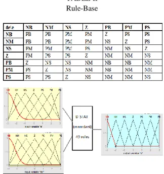
controller is used for controlling real and reactive power by mitigating their transient period. In this work FLC is used in main controllers of D-STATCOM i.e. modulation index controller and delta controller. FLC works on two inputs they are error and derivative in error. Figure.3 shows the fuzzy membership function of error and derivative error, both of the inputs use Gaussian and triangle membership functions while the output use only triangle membership function.
The rule-base of fuzzy is the mapping between the two inputs and output. There are seven linguistic variables for each input so 49 rules are designed for this FLC. One illustrative rule is as follows:
If e is NB and de is NB then output is PB.
If the one of input error is negative error and another input derivative of error is negative big then the output is positive big. Table 2 shows rule-base of 49 rules.
TABLE II Rule-Base
Fig.3: Membership function of FLC
VII. SIMULATION RESULTS
www.ijseat.com Page 600
mitigates the transient period of the active and reactive power by decreasing their settling time from 0.8sec to 0.3 sec as shown in Figure 4.
(a)
(b)
Fig.4 P and Q of the feeder line (a) without FLC (b) with FLC
Load on the feeder line is 50KW and 34.8KVARs at 0.82p.f. Starting of simulation i.e. up to t=6sec entire load is fed by feeder line alone. Feeder line is able to provide 50KW and 24.8KVAR to the load as shown in figure 5. Therefore there is deficiency in supplying required amount of reactive power to the load by feeder line. D-STATCOM starts providing VAR compensation at t=6secs and gives around 15KVARs, then reactive power of feeder is decreased to 20KVARs from 24.8KVARs as shown in figure 6(b), therefore total KVAR of load is fed by both D-STATCOM and feeder line. Figure 6 shows active and reactive delivered to the feeder line by the D-STATCOM inverter without and with FLC.
Fig.5 P and Q of the feeder line
(a)
(b)
Fig.6 P and Q delivered to the Feeder Line by the D-STATCOM Inverter (a) without FLC (b) with FLC
Figure 7 shows the modulation index, delta and wind turbine output power during 20sec simulation without and with FLC. In the third graph of 7(b) wind provide active power of 10KW at the same instant active power of feeder line decreased by the same amount. This shows that wind energy is not adding power instead it is replacing the power coming from conventional energy.
(a)
0 0.1 0.2 0.3 0.4 0.5 0.6 0.7 0.8 0.9 1
0 1 2 3 4 5 6x 10
4 W at ts a nd V A R s
P and Q of the Feeder Line
P Q
0 0.1 0.2 0.3 0.4 0.5 0.6 0.7 0.8 0.9 1 0 1 2 3 4 5 6x 10
4 W a tt s a n d V A R s
P and Q of the Feeder Line P Q
0 2 4 6 8 10 12 14 16 18 20 0 1 2 3 4 5 6x 10
4 W at ts a nd V A R s
P and Q of the Feeder Line P Q
0 2 4 6 8 10 12 14 16 18 20 0
1 2 3x 10
4 W a tt s a n d V A R s
P and Q Delivered to the Feeder Line by the D-STATCOM Inverter P Q
0 2 4 6 8 10 12 14 16 18 20 0
1 2 3x 10
4 W a tt s a n d V A R s
P and Q Delivered to the Feeder Line by the D-STATCOM Inverter P Q
0 2 4 6 8 10 12 14 16 18 20
0.6 0.8 1
The Modulation Index
0 2 4 6 8 10 12 14 16 18 20
-20 0 20 D e g r e e s Angle Delta
0 2 4 6 8 10 12 14 16 18 20 0 5000 10000 15000 Time W a t t s
www.ijseat.com Page 601
(b)
Fig.7 Modulation Index, Angle Delta and Wind Turbine Output Power (a) without FLC and (b) with
FLC
VIII. CONCLUSION
In this work distributed energy system is presented which provides active power to the load by replacing the power provided by the conventional energy. D-STATCOM provides VAR compensation by providing required amount of reactive power along with feeder line. It is observed how active power and reactive power is controlled by delta
controller and modulation index controller
respectively. In the starting of the simulation there is transient period in the output waveforms due to the presence of inductors and capacitors. These energy storing devices cannot be replaced so FLC technique is used to mitigate the transient period. Finally simulation results are compared between without FLC and with FLC. It is observed that transient period is mitigated by reducing the settling time.
REFERENCES
[1] Ahmed. F. Zobaa and Bimal. K. Bose, “Renewable Energy, Global Warming Problem and Impact of Power Electronics”, International Conference on Renewable Energies and Power Quality (ICREPQ‟11) Las Palmas de Gran Canaria (Spain), 13th to 15th April, 2011.
[2] Stanley R. Bull, “Renewable Energy Today and Tomorrow” IEEE, Vol. 89, No. 8, August 2001. [3] Jing Zhang, “Power Electronics in Future
Electrical Power Grids”, Dept. of Systems
Engineering University of Arkansas at Little Rock Little Rock, Arkansas, USA.
[4] Junichi Arai, Kenji Iba, Toshihisa Funabashi, Yosuke Nakanishi, Kaoru Koyanagi, and Ryuichi Yokoyama, “Power electronics and its application to renewable energy in japan”, IEEE Circuits And Systems Magazine 1531-636x/08/$25.00©2008. [5] Veeraiah Kumbha and N. Sumathi, “Power quality improvement of Distribution lines using DSTATCOM under various loading conditions”, International Journal of Modern Engineering Research (IJMER) Vol. 2, Issue 5, Sep.-Oct 2012 pp-3451-3457.
[6] Mudathir Funsho Akorede, Hashim Hiza and, Edris Pouresmaeil, “Distributed energy sources and benefits to the environment”. M.F.Akoredeetal. Renewable and Sustainable Energy Reviews 14 (2010) 724–734.
[7] Thomas Ackermann, Go¨ran Andersson, and
Lennart So¨der, “Distributed generation: a
definition”, Electric Power Systems Research 57 (2001) 195–204.
[8] Alian Chen and Xiangning He, “Research on Hybrid-Clamped Multilevel-Inverter Topologies”, IEEE Transactions on Industrial Electronics, Vol. 53, No. 6, December 2006.
[9] Ritu Shakya1, Kritika Rajanwal2, Sanskriti Patel and Smita Dinkar, “Design and Simulation of PD, PID and Fuzzy Logic Controller for Industrial Application”, International Journal of Information and Computation Technology ISSN 0974-2239 Volume 4, Number 4 (2014), pp. 363-368.
[10] Yüksel OĞUZ, “Fuzzy PI Control with Parallel Fuzzy PD Control for Automatic Generation Control of a Two-Area Power Systems”, Gazi University Journal of Science 24(4):805-816 (2011).
[11] Ting-En Lee, Juhng-Perng Su and Ker-Wei Yu, ”A Practical Design of Fuzzy PD Controller and Its Application to Magnetic Levitation System”, 2008 IEEE International Conference on Systems, Man and Cybernetics (SMC 2008).
0 2 4 6 8 10 12 14 16 18 20
0.6 0.8 1
The Modulation Index
0 2 4 6 8 10 12 14 16 18 20
-20 0 20
D
e
g
re
e
s
Angle Delta
0 2 4 6 8 10 12 14 16 18 20
0 5000 10000 15000
Time
W
a
tt
s