Implementation of A 15-Level Inverter With MMC Technique Using
Facts Equipment
Nageswara Rao Mulasa1, N.Sirisha2
1PG Scholar, Pydah College of Engineering, Kakinada, AP, India. 2Associate Professor, Pydah College of Engineering, Kakinada, AP, India. Abstract—The implementation of a 15-level inverter
with modular multilevel converter (MMC) technique for single-phase wind energy inverter (WEI) using facts technology is presented in this paper. With this WEI proposed inverter, for small size wind applications will eliminate the use of capacitor banks and FACTS devices are work to control the PF of the distribution lines. The goal of this manuscript is to initiate new ways to enlarge the value of renewable energy systems into the distribution systems with the help of FACTS technology. The function of the proposed inverter is to transport active power to the grid as well as maintenance the PF of the local power lines constant at a target PF at any rate of the incoming active power from the wind turbine. The proposed single-phase wind power inverter is placed between the wind turbine and the grid. This inverter is able to control active and reactive powers transferred to the grid. The new types of converters with FACTS technology will significantly reduce the total cost of the renewable energy application. A modular multilevel converter is used to meet all the requirements with IEEE standards, total harmonic distortion (THD), efficiency, and total cost of the system. The proposed control strategy regulates the active and reactive power using power angle and modulation index, respectively. The simulations for 5, 7, 9, 11, 13 and 15-level inverters have been done in MATLAB/Simulink. The % THDs have presented for all these levels.
Index Terms—Modular multilevel converter (MMC), multilevel inverter (MLI), wind energy inverter (WEI)
I. INTRODUCTION
The power electronic devices are regularly used to convert the nonconventional forms of energy to the appropriate energy for power grids, in terms of voltage and frequency. In permanent magnet (PM) wind applications, a back-to-back converter is generally utilized to attach the generator to the grid. A
rectifier prepared with a maximum power point tracker (MPPT), converts the output power of the wind turbine to a dc power. The dc power is then converted to the most wanted ac power for power lines using an inverter and a transformer. With modern developments in wind energy, utilizing smarter wind energy inverters (WEIs) has become an imperative subject.
There are a lot of single-phase lines in the United States, which power small farms or remote houses. Such customers have the potential to produce their required energy using a small-to-medium-size wind turbine. Increasing the number of small-to-medium wind turbines will make several troubles for local utilities such as harmonics or power factor (PF) issues. A high PF is generally desirable in a power system to decrease power losses and improve voltage regulation at the load. It is often desirable to adjust the PF of a system to near 1.0. When reactive elements supply or absorb reactive power near the load, the apparent power is reduced. In other words, the current drawn by the load is reduced, which decreases the power losses.
by the modulation index m. There are a large number of publications on integration of renewable energy systems into power systems. A list of complete publications on FACTS applications for grid integration of wind and solar energy was presented in [3]. In [4], new commercial wind energy converters with FACTS capabilities are introduced without any detailed information regarding the efficiency or the topology used for the converters.
In [5], a complete list of the most important multilevel inverters was reviewed. Also, different modulation methods such as sinusoidal pulse width modulation (PWM), selective harmonic elimination, optimized harmonic stepped waveform technique, and space vector modulation were discussed and compared. Among all multilevel topologies, the cascaded H-bridge multilevel converter is very well known for STATCOM applications for several reasons. The main reason is that it is simple to obtain a high number of levels, which can help to connect STATCOM directly to medium voltage grids. The modular multilevel converter (MMC) was introduced in the early 2000s. Reference [15] describes a MMC converter for high voltage DC (HVDC) applications. This paper mostly looks at the main circuit components. Also, it compares two different types of MMC, including H-bridge and full-bridge sub-modules. In [9] and [16], a new single-phase inverter using hybrid clamped topology for renewable energy systems is presented.
The proposed inverter is placed between the renewable energy source and the main grid. The main drawback of the proposed inverter is that the output current has significant fluctuations that are not compatible with IEEE standards. The authors believe that the problem is related to the snubber circuit design. Several other applications of custom power electronics in renewable energy systems exist, including an application of a custom power interface where two modes of operation, including an active power filter and a renewable energy STATCOM. Similar to wind farms, solar farms are idle during nights. We proposed a control strategy that makes the solar farms to act as STATCOMs during night when they are not able to produce active power.
The main purpose of the PV-STATCOM system is to improve the voltage control and the PF correction on three-phase transmission systems. In this paper, the proposed WEI utilizes MMC topology,
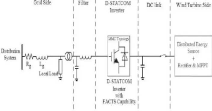
this inverter will eliminate the need to use a separate capacitor bank or a STATCOM device to fix the PF of the local distribution grids. Obviously, depending on the size of the power system, multiple inverters might be used in order to reach the desired PF. The exceptional work in this document is the use of MMC topology for a single phase voltage-source inverter, which meets the IEEE standard 519 necessities, and is able to control the PF of the grid anyway of the wind speed Fig. 1 shows the absolute grid-connected mode arrangement of the projected inverter. The dc link of the inverter is associated to the wind turbine through a rectifier using MPPT and its output terminal is connected to the utility grid through a series-connected second-order filter and a distribution transformer.
Fig. 1 Complete configuration of the proposed inverter with FACTS capability
II. MODULAR MULTILEVEL CONVERTER
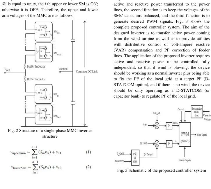
connection of cells, simple realization of redundancy, and possibility of a common dc bus. Fig. 2 shows the circuit configuration of a single-phase MMC and the structure of its SMs consisting of two power switches and a floating capacitor.
The output voltage of each SM (vo) is either equal to its capacitor voltage (vc) or zero, depending on the switching states. The buffer inductors must provide current control in each phase arm and limit the fault currents. To describe the operation of MMC, each SM can be considered as a two pole switch. If
Sui, which is defined as the status of the ith
sub-module in the upper arm, is equal to unity, then the output of the ith SM is equal to the corresponding capacitor voltage; otherwise it is zero. Likewise, if Sli which is defined as the status of the i th sub-module in the lower arm, is equal to unity, then the output of the
ith lower SM is equal to the corresponding capacitor
voltage; otherwise it is zero. Generally, when Sui or
Sli is equal to unity, the i th upper or lower SM is ON;
otherwise it is OFF. Therefore, the upper and lower arm voltages of the MMC are as follows:
Fig. 2 Structure of a single-phase MMC inverter structure
Where v11 and v12 are the voltages of the upper and lower buffer inductors, n is the number of voltage levels, and vci is the voltage of the i th SMs capacitor in upper arm or lower arm. A single-phase 11-levelMMC inverter consists of 20 SMs which translates to 40 power switches, 20 capacitors, and 2 buffer inductors. The dc and ac voltages of the 11-level MMC are described by
III. PROPOSED CONTROL STRATEGY
The proposed controller consists of three major functions. The first function is to control the active and reactive power transferred to the power lines, the second function is to keep the voltages of the
SMs’ capacitors balanced, and thethird function is to generate desired PWM signals. Fig. 3 shows the complete proposed controller system. The aim of the designed inverter is to transfer active power coming from the wind turbine as well as to provide utilities with distributive control of volt-ampere reactive (VAR) compensation and PF correction of feeder lines. The application of the proposed inverter requires active and reactive power to be controlled fully independent, so that if wind is blowing, the device should be working as a normal inverter plus being able to fix the PF of the local grid at a target PF (D-STATCOM option), and if there is no wind, the device should be only operating as a D-STATCOM (or capacitor bank) to regulate PF of the local grid.
This translates to two modes of operation: 1) when wind is blowing and active power is coming from the wind turbine: the inverter plus D-STATCOM mode. In this mode, the device is working as a regular inverter to transfer active power from the renewable energy source to the grid as well as working as a normal D-STATCOM to regulate the reactive power of the grid in order to control the PF of the grid and 2) when wind speed is zero or too low to generate active power: the D-STATCOM mode. In this case, the inverter is acting only as a source of reactive power to control the PF of the grid, as a D-STATCOM. This option eliminates the use of additional capacitor banks or external STATCOMs to regulate the PF of the distribution feeder lines. Obviously, the device is capable of outputting up to its rated maximum real power and/or reactive power, and will always output all real power generated by the wind turbine to the grid. The amount of reactive power, up to the design maximum, is dependent only on what the utility asks the device to produce. Generally, (5) and (6) dictate the power flow between a STATCOM device and power lines
Where X is the inductance between the STATCOM (here as inverter) and the grid which is normally considered as output filter inductance added to the transmission line inductance. The root mean square (RMS) voltage of the STATCOM (= inverter) is given as Es and is considered to be out of phase by an angle ofδto the RMS line voltage E1.
In the proposed control strategy, active and reactive power transferred between the inverter and the distribution grid is controlled by selecting both the voltage level of the inverter and the angle δ between the voltages of inverter and grid, respectively. The amplitude of the inverter voltage is regulated by changing the modulation index m and the angle δ by adding a delay to the firing signals which concludes
In this paper, m is the key factor to control the reactive power compensation and its main task is
control between the inverter and the grid. Several assumptions should be considered for the proposed controller which is as: 1) the load on the feeder line should be considered fixed for a small window of time and there is no change in the load during a cycle of the grid frequency; 2) the feeder line can be accurately modeled as a constant P, Q load. This means that the power produced by a wind turbine will displace other power on the feeder line and not add to it; and 3) although making a change in m orδhas effect on both (7) and (8), it is assumed that a change in the modulation index will predominantly affect Q, while a change in delta will predominantly affect P. Any effect on Q from a small change in delta is thus ignored. This results in controlling P and Q
independently. Equation (9) shows the relation between the target reactive power and the target PF
Where PG is the amount of active power on the grid,
QT is the target amount of reactive power, and PFT is
the target PF desired by the utility. So, QT can be calculated as
Using (9) and (10), the target reactive power for the grid is determined and is compared with the actual value of the reactive power of the grid. Using a PI compensator will determine the desired value for the modulation index. The power angle is also determined by comparing the actual dc voltage of the inverter with a reference value. A PI compensator determines the desired value for the power angle. The second function of the controller systems is to keep the capacitors’
Where nupperArm and nlowerArm are the numbers of SMs which are ON (Sc is ON and Sm is OFF in Fig. 1) in the upper arm or lower arm, respectively. In an 11-level MMC inverter, there are ten upper and ten lower SMs where each SM has a capacitor. For instance, in voltage level 1 of Table I, all the upper SMs should be OFF and all the lower SMs should be ON, which translates to the fact that the main switches Sm of all upper SMs and the auxiliary switches (Sc) of all lower SMs have to be ON and all the other switches have to be OFF. In this case, the input dc voltage is applied only to the ten lower capacitors, so that the output voltage is vDC/2. Fig. 5 illustrates the selection of capacitors for different voltage levels shown in Table I.
The most critical issue to control MMC is to maintain the voltage balance across all the capacitors. Therefore, theSMs’ voltages are measured and sorted in descending order during each cycle. If the current flowing through the switches is positive, so that capacitors are being charged, nupperArm and
nupperArm and of the SMs in upper arm and lower
arm with the lowest voltages are selected, respectively. As a result, ten capacitors with lowest voltages are chosen to be charged. Likewise, if the current flowing through the switches is negative, so that capacitors are being discharged, nupperArm and nupperArm of the SMs in upper arm and lower arm with highest voltages are selected, respectively. As a result, ten capacitors with highest voltages are chosen to be discharged.
Consequently, the voltages of the SMs’ capacitors are balanced. Considering Table I and based on the direction of the current flowing through the switches, the proper algorithm will be selected to maintain capacitor balance.
The third function of the controller system is the PWM generation block. In this block, based on the desired modulation index, power angle, voltages of the capacitors, direction of the current flowing through the switches and using Table I, the controller generates the PWM signals in order to meet all the system requirements.
TABLE I
OPERATING REGIONS FOR AN 11-LEVEL MMC INVERTER
IV. SIMULATION RESULTS
Fig 5 simulation of Structure of a single-phase MMC inverter structure
Fig 6 CPWM waveforms for an 11-level MMC
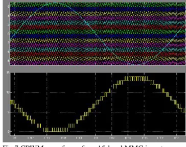
Fig 7 CPWM waveforms for a 15-level MMC inverter
Fig 8 Simulated output voltage of a 5-level inverter
Fig 10 Simulated output voltage of a 7-level inverter
Fig 11 % THD of a 7-level inverter
Fig 12 Simulated output voltage of a 9-level inverter
Fig 13 % THD of a 9-level inverter
Fig 14 Simulated output voltage of a 11-level inverter
Fig 15 % THD of an 11-level inverter
Fig 16 Simulated output voltage of a 13-level inverter
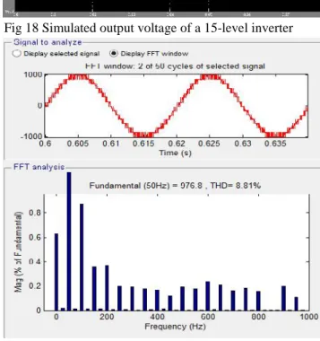
Fig 18 Simulated output voltage of a 15-level inverter
Fig 19 % THD of a 13-level inverter
CONCLUSION
In this paper, the concept of a new multilevel inverter with FACTS capability for small-to-mid-size wind installations is presented. The proposed system demonstrates the application of a new inverter with FACTS capability in a single unit without any additional cost. Replacing the traditional renewable energy inverters with the proposed inverter will eliminate the need of any external STATCOM devices to regulate the PF of the grid. Clearly, depending on the size of the compensation, multiple inverters may be needed to reach the desired PF. This shows a new way in which distributed renewable sources can be used to provide control and support in distribution systems. The proposed controller system adjusts the active power by changing the power angle (delta) and the reactive power is controllable by the modulation index m. The simulation results for a 15-level inverter are presented in MATLAB/Simulink.
[1] U.S. Solar Market Insight, 2010 Year End Review
Executive Summary, SEIA, Washington, DC, USA,
2011.
[2] AWEA U.S. Wind Industry Annual Market Report
Year Ending 2010, AWEA, Washington, DC, USA,
2011.
[3] S. A. Rahman, R. K. Varma, and W. H.
Litzenberger, “Bibliography of FACTS applications for grid integration of wind and PV solar power systems: 1995–2010 IEEE working group report,” in Proc. IEEE Power Energy Soc. General Meeting, Jul.
2011, pp. 1–17.
[4] A. Beekmann, J. Marques, E. Quitmann, and S.
Wachtel, “Wind energy converters with FACTS capabilities for optimized integration of wind power
into transmission and distribution systems,” in Proc. CIGRE/IEEE PES Joint Symp. Integr. Wide, Scale Renew. Resour. Power Del. Syst.,
Jul. 2009, pp. 1–9.
[5] J. Rodriguez, J. S. Lai, and F. Z. Peng, “Multilevel
inverters: Survey of topologies, controls, and
applications,” IEEE Trans. Ind. Appl., vol. 49, no. 4,
pp. 724–738, Aug. 2002.
[6] F. Z. Peng, J. S. Lai, J. W. McKeever, and J.
VanCoevering, “A multilevel voltage-source inverter with separate DC sources for static VAr generation,” IEEE Trans. Ind. Appl., vol. 32, no. 5, pp. 1130–1138, Oct. 1996.
[7] L. M. Tolbert and F. Z. Peng, “Multilevel
converters as a utility interface for renewable energy
systems,” in Proc. IEEE Power Eng. Soc. Summer Meeting, vol. 2. Jul. 2000, pp. 1271–1274.
[8] S. Kouro, M. Malinowski, K. Gopakumar, J. Pou, L. G. Franquelo, B. Wu, et al., “Recent advances and
industrial applications of multilevelconverters,”IEEE Trans. Ind. Electron., vol. 57, no. 8, pp. 2553–2580, Aug. 2010.
[9] C. Tareila, P. Sotoodeh, and R. D. Miller, “Design
and control of a single-phase D-STATCOM inverter
for wind application,” inProc. PEMWA, Jul. 2012, pp.
1–5.
[10] B. Gultekin and M. Ermis, “Cascaded multilevel
converter-based transmission STATCOM: System design methodology and development of a 12 kV ±12
MVAr power stage,” IEEE Trans. Power Electron.,
vol. 28, no. 11, pp. 4930–4950, Nov. 2013.
[11] K. Sano and M. Takasaki, “A transformerless D -STATCOM based on a multivoltage cascade converter
[12] X. Liang, Y. Xu, X. Chen, and C. Guo, “The
simulation research of STATCOM based on cascaded multi-level converter,” in Proc. 4th Int. Conf. Electr. Util. DRPT, Jul. 2011, pp. 494–498.
[13] M. Davies, M. Dommaschk, J. Dorn, J. Lang, D. Retzmann, and D. Soerangr, HVDC PLUS Basic and
Principle of Operation. Erlandgen, Germany: Siemens
AG Energy Sector, 2009.
[14] B. Gemmell, J. Dorn, D. Retzmann, and D.
Soerangr, “Prospects of multilevel VSC technologies
for power transmission,” in Proc. IEEE Transmiss. Distrib. Conf. Exposit., Apr. 2008, pp. 1–16.
[15] C. D. Barker and N. M. Kirby, “Reactive power loading of components within a modular multi-level
HVDC VSC converter,” in Proc. IEEE EPEC, Oct.
2011, pp. 86–90.
[16] C. P. Tareila, “A single-phase D-STATCOM Inverter for distributed energy sources,” M.S. thesis,
Dept. Electr. Comput. Eng., Kansas State Univ., Manhattan, KS, USA, Aug. 2011.
[17] Z. Yang, C. Shen, L. Zhang, M. L. Crow, and S.
Atcitty, “Integration of a STATCOM and battery
energy storage,”IEEE Trans. Power Syst., vol. 16, no.
2, pp. 254–260, May 2001.
[18] S. Chakraborty, B. Kroposki, and W. Kramer,
“Evaluation of control and voltage regulation functionalities in a single-phase utility-connected
inverter for distributed energy applications,” in Proc. IEEE ECCE, Sep. 2009, pp. 1753–1759.
[19] R. K. Varma, S. A. Rahman, A. C. Mahendra, R. Seethapathy, and T. Vanderheide, “Novel nighttime
application of PV solar farms as STATCOM