Analysis of ANN Based Active Power Filter Performance For Renewable
Power Generation System
Manasa Rupa Devi Moka1, N.Sirisha2
1PG Scholar, Pydah College of Engineering, Kakinada, AP, India. 2Associate Professor, Pydah College of Engineering, Kakinada, AP, India.
Abstract—In this paper analysis of ANN based active power filter performance for renewable power generation system has been proposed. A four leg VSC is used in this system, and this allows the reparation of current harmonic components, as well as unbalanced current generated by single-phase nonlinear loads. A new ANN controller has been proposed to improve the %THD in the non linear current. Generally the PI controller has more %THD; the ANN controller has more effect and will reduce the %THD. %THD table shows the differences between conventional controller and ANN controller. The simple numerical model of the active power filter, together with the effect of the equivalent power system impedance, is derived and used to design the analytical control algorithm. The simulation result shows the efficiency of the system using MATLAB/SIMULATION software. The reimbursement performance of the proposed active power filter and the associated control scheme with ANN controller have been tested under stable status and transitory operating environment through the simulation results.
Index Terms—Active power filter, current control, four-leg converters, predictive control
I. INTRODUCTION
The non-uniform character of power generation openly affects voltage regulation and creates voltage distortion in power systems. This new scenario in power distribution systems will require more complicated reimbursement techniques. Although active power filters implemented with three-phase four-leg voltage-source inverters (4L-VSI) have already been existing in the technical literature, the primary contribution of this paper is a predictive control algorithm designed and implemented specifically for this application. Traditionally, active power filters have been controlled using pretuned controllers, such as PI-type or adaptive, for the current as well as for the dc-voltage loops. PI controllers must be premeditated
based on the corresponding linear model, while analytical controllers use the nonlinear model, which is closer to real operating conditions.
An precise model obtained using analytical controllers improves the presentation of the active power filter, particularly during transitory operating conditions, because it can quickly follow the current-reference signal while maintaining a constant dc-voltage. So far, implementations of predictive control in power converters have been used mostly in induction motor drives. In the case of motor drive applications, predictive control represents a very instinctive control scheme that handles multivariable distinctiveness, simplify the behavior of dead-time compensations, and permits pulse-width modulator replacement. However, these kinds of applications present disadvantages related to oscillations and unsteadiness created from unknown load parameters. One advantage of the projected algorithm is that it hysterics well in active power filter applications, since the power converter output parameters are well known. These output parameters are obtained from the converter output ripple filter and the power system corresponding impedance.
The converter output ripple filter is part of the active power filter design and the power system impedance is obtained from recognized usual procedures. In the case of unknown system impedance parameters, an estimation method can be used to derive an accurate R–L equivalent impedance model of the
system. This paper presents the arithmetical model of the 4L-VSI and the ideology of operation of the proposed predictive control scheme, together with the propose procedure. The complete description of the selected current reference generator implemented in the active power filter is also presented. Finally, the proposed active power filter and the usefulness of the correlated control scheme compensation are established through simulation results.
Fig. 1 shows the configuration of a typical power distribution system with renewable power generation. It consists of various types of power generation units and different types of loads. Wind and sunlight, are typically used to generate electricity for residential users and small industries. Both types of power generation use ac/ac and dc/ac static PWM converters for voltage conversion and battery banks for long term energy storage. These converters perform maximum power point tracking to extract the maximum energy possible from wind and sun. The electrical energy consumption behavior is random and unpredictable, and therefore, it may be single- or three-phase, balanced or unbalanced, and linear or nonlinear. An active power filter is connected in parallel at the point of common coupling to compensate current harmonics, current unbalance, and reactive power.
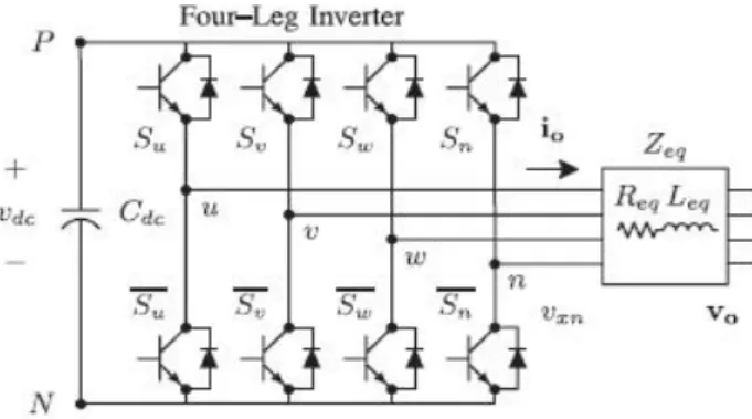
It is composed by an electrolytic capacitor, a four-leg PWM converter, and a first-order output ripple filter, as shown in Fig. 2. This circuit considers the power system equivalent impedance Zs, the converter output ripple filter impedance Zf, and the load impedance ZL. The four-leg PWM converter topology is shown in Fig. 3. This converter topology is similar to the conservative three-phase converter with the fourth leg connected to the neutral bus of the system. The fourth leg increases switching states from 8 (23) to 16 (24), improving control flexibility and output voltage quality, and is suitable for current unbalanced compensation.
Fig. 1 Stand-alone hybrid power generation system with a shunt active power filter
Fig. 2 Three-phase equivalent circuit of the proposed shunt active power filter
Fig. 3 Two-level four-leg PWM-VSI topology The voltage in any leg x of the converter, measured from the neutral point (n), can be expressed in terms of switching states, as follows:
The mathematical model of the filter derived from the equivalent circuit shown in Fig. 2 is
Where Req and Leq are the 4L-VSI output parameters expressed as Thevenin impedances at the converter output terminals Zeq. Therefore, the Thevenin
equivalent impedance is determined by a series connection of the ripple filter impedance Zf and a parallel arrangement between the system equivalent impedance Zs and the load impedance ZL
impedance is neglected, and that the series reactance is in the range of 3–7% p.u., which is an acceptable approximation of the real system. Finally, in (2) Req =
Rf and Leq = Ls + Lf.
III. DIGITAL PREDICTIVE CURRENT CONTROL
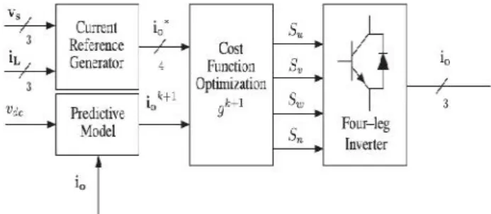
The block diagram of the proposed digital predictive current control scheme is shown in Fig. 4. This control scheme is basically an optimization algorithm and, therefore, it has to be implemented in a microprocessor. Consequently, the analysis has to be developed using discrete mathematics in order to consider additional restrictions such as time delays and approximations. The main characteristic of predictive control is the use of the system model to predict the future behavior of the variables to be controlled. The controller uses this information to select the optimum switching state that will be applied to the power converter, according to predefined optimization criteria. The predictive control algorithm is easy to implement and to understand, and it can be implemented with three main blocks, as shown in Fig. 4.
1) Current Reference Generator: This unit is designed
to generate the required current reference that is used to compensate the undesirable load current components. In this case, the system voltages, the load currents, and the dc-voltage converter are measured, while the neutral output current and neutral load current are generated directly from these signals (IV).
2) Prediction Model: The converter model is used to
predict the output converter current. Since the controller operates in discrete time, both the controller and the system model must be represented in a discrete time domain. The discrete time model consists of a recursive matrix equation that represents this prediction system. This means that for a given sampling time Ts, knowing the converter switching states and control variables at instant kTs, it is possible to predict the next states at any instant [k + 1]Ts .Due to the first-order nature of the state equations that describe the model in (1)–(2), a sufficiently accurate first-order approximation of the derivative is considered in this paper
The 16 possible output current predicted values can be obtained from (2) and (4) as
As shown in (5), in order to predict the output current io at the instant (k + 1), the input voltage value vo and the converter output voltage vxN , are required. The algorithm calculates all 16 values associated with the possible combinations that the state variables can achieve.
Fig. 4 Proposed predictive digital current control block diagram
3) Cost Function Optimization: In order to select the
optimal switching state that must be applied to the power converter, the 16 predicted values obtained for io[k + 1] are compared with the reference using a cost function g, as follows:
The output current (io) is equal to the reference (i∗o) when g = 0. Therefore, the optimization goal of the cost function is to achieve a g value close to zero. The voltage vector vxN that minimizes the cost function is chosen and then applied at the next sampling state. During each sampling state, the switching state that generates the minimum value of g is selected from the 16 possible function values. The algorithm selects the switching state that produces this minimal value and applies it to the converter during the k + 1 state.
IV. CURRENT REFERENCE GENERATION A dq-based current reference generator
reference signal affecting compensation performance. The current reference signals are obtained from the corresponding load currents as shown in Fig. 5. This module calculates the reference signal currents required by the converter to compensate reactive power, current harmonic and current imbalance. The displacement power factor (sin φ(L) ) and the maximum total harmonic distortion of the load (THD(L) ) defines the relationships between the apparent power required by the active power filter, with respect to the load, as shown
Where the value of THD (L) includes the maximum compensable harmonic current, defined as double the sampling frequency fs. The frequency of the maximum current harmonic component that can be compensated is equal to one half of the converter switching frequency. The dq-based scheme operates in a rotating reference frame; therefore, the measured currents must be multiplied by the sin(wt) and cos(wt) signals. By using dq-transformation, the d current component is synchronized with the corresponding phase-to-neutral system voltage, and the q current component is phase-shifted by 90◦. The sin (wt) and cos(wt) synchronized reference signals are obtained from a synchronous reference frame (SRF) PLL. The SRF-PLL generates a pure sinusoidal waveform even when the system voltage is severely distorted. Tracking errors are eliminated, since SRF-PLLs are designed to avoid phase voltage unbalancing, harmonics (i.e., less than 5% and 3% in fifth and seventh, respectively), and offset caused by the nonlinear load conditions and measurement errors. Equation (8) shows the relationship between the real currents iLx(t) (x = u, v,w) and the associated dq components (id and iq )
A low-pass filter (LFP) extracts the dc component of the phase currents id to generate the harmonic reference components −_id. The reactive reference components of the phase-currents are obtained by phase-shifting the corresponding ac and dc components of iq by 180◦. In order to keep the dc-voltage constant, the amplitude of the converter
reference current must be modified by adding an active power reference signal ie with the d-component, as will be explained in Section IV-A. The resulting signals i∗d
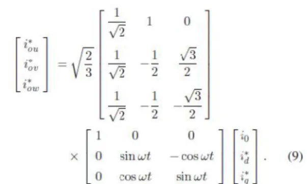
and i∗q are transformed back to a three-phase system
by applying the inverse Park and Clark transformation, as shown in (9). The cutoff frequency of the LPF used in this paper is 20 Hz
The current that flows through the neutral of the load is compensated by injecting the same instantaneous value obtained from the phase-currents, phase-shifted by 180 ◦, as shown next
Fig. 6 Relationship between permissible unbalance load currents, the corresponding third-order harmonic
content, and system current imbalance
One of the major advantages of the dq-based current reference generator scheme is that it allows the implementation of a linear controller in the dc-voltage control loop. However, one important disadvantage of the dq-based current reference frame algorithm used to generate the current reference is that a second order harmonic component is generated in id and iq under unbalanced operating conditions. The amplitude of this harmonic depends on the percent of unbalanced load current (expressed as the relationship between the negative sequence current iL,2 and the positive sequence current iL,1). The second-order harmonic cannot be removed from id and iq , and therefore generates a third harmonic in the reference current when it is converted back to abc frame. Fig. 6 shows the percent of system current imbalance and the percent of third harmonic system current, in function of the percent of load current imbalance. Since the load current does not have a third harmonic, the one generated by the active power filter flows to the power system.
A. DC-Voltage Control
The dc-voltage converter is controlled with a traditional PI controller. This is an important issue in the evaluation, since the cost function (6) is designed using only current references, in order to avoid the use of weighting factors. Generally, these weighting factors are obtained experimentally, and they are not well defined when different operating conditions are required. Additionally, the slow dynamic response of the voltage across the electrolytic capacitor does not affect the current transient response. For this reason, the PI controller represents a simple and effective alternative for the dc-voltage control.√The dc-voltage remains constant (with a minimum value of 6 vs(rms) ) until the active power absorbed by the converter decreases to a level where it is unable to compensate for its losses.
Fig. 7 DC-voltage control block diagram
The active power absorbed by the converter is controlled by adjusting the amplitude of the active power reference signal ie, which is in phase with each phase voltage. In the block diagram shown in Fig. 5, the dc-voltage vdc is measured and then compared with a constant reference value v∗ dc. The error (e) is processed by a PI controller, with two gains, Kp and Ti . Both gains are calculated according to the dynamic response requirement. Fig. 7 shows that the output of the PI controller is fed to the dc-voltage transfer function Gs, which is represented by a first-order system (11)
The equivalent closed-loop transfer function of the given system with a PI controller (12) is shown in (13)
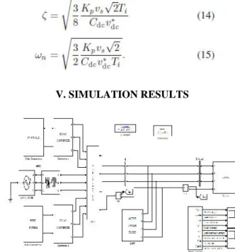
Since the time response of the dc-voltage control loop does not need to be fast, a damping factorζ = 1and a natural angular speedωn= 2π·100 rad/s are used to obtain a critically damped response with minimal voltage oscillation. The corresponding integral time Ti = 1/a (13) and proportional gain Kp can be calculated as
V. SIMULATION RESULTS
Fig. 9 circuit of the proposed shunt active power
Fig. 10 dq-based current controller TABLE-1
%THD OF SOURCE CURRENTS USING PI AND ANN CONTROLLERS
Fig. 11 Simulated waveforms of the proposed control scheme (a) Phase to neutral source voltage (b) Load Current (c) Active power filter output current (d) Load
neutral current (e) System neutral current (f) System currents. (g) DC voltage converter (h) grid current
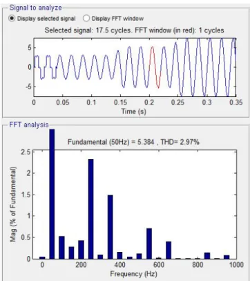
Fig 12 %THD using PI controller Fig. 9 circuit of the proposed shunt active power
Fig. 10 dq-based current controller TABLE-1
%THD OF SOURCE CURRENTS USING PI AND ANN CONTROLLERS
Fig. 11 Simulated waveforms of the proposed control scheme (a) Phase to neutral source voltage (b) Load Current (c) Active power filter output current (d) Load
neutral current (e) System neutral current (f) System currents. (g) DC voltage converter (h) grid current
Fig 12 %THD using ANN controller CONCLUSION
Improved dynamic current harmonics and a reactive power compensation scheme for power distribution systems with generation from renewable sources has been proposed to improve the current quality of the distribution system. Advantages of the proposed scheme are related to its simplicity, modeling, and implementation. The use of a predictive control algorithm for the converter current loop proved to be an effective solution for active power filter applications, improving current tracking capability, and transient response. Simulated and experimental results have proved that the proposed predictive control algorithm is a good alternative to classical linear control methods. The predictive current control algorithm is a stable and robust solution. Simulated results have shown the compensation effectiveness of the proposed active power filter. %THD table shows the differences between conventional controller and ANN controller. The compensation performance of the proposed active power filter and the associated control scheme with ANN controller have been tested under steady state and transient operating conditions through the simulation results.
REFERENCES
[1] J. Rocabert, A. Luna, F. Blaabjerg, and P. Rodriguez, “Control of power converters in AC
microgrids,”IEEE Trans. Power Electron., vol. 27, no.
11, pp. 4734–4749, Nov. 2012.
[2] M. Aredes, J. Hafner, and K. Heumann, “Three-phase four-wire shunt active filter control strategies,”
IEEE Trans. Power Electron., vol. 12, no. 2, pp. 311– 318, Mar. 1997.
[3] S. Naidu and D. Fernandes, “Dynamic voltage restorer based on a fourleg voltage source converter,”
Gener. Transm. Distrib., IET, vol. 3, no. 5, pp. 437– 447, May 2009.
[4] N. Prabhakar and M. Mishra, “Dynamic hysteresis current control to minimize switching for three-phase four-leg VSI topology to compensate nonlinear load,”
IEEE Trans. Power Electron., vol. 25, no. 8, pp. 1935– 1942, Aug. 2010.
[5] V. Khadkikar, A. Chandra, and B. Singh, “Digital signal processor implementation and performance evaluation of split capacitor, four-leg and three h-bridge-based three-phase four-wire shunt active filters,”
Power Electron., IET, vol. 4, no. 4, pp. 463–470, Apr. 2011.
[6] F. Wang, J. Duarte, and M. Hendrix, “Grid-interfacing converter systems with enhanced voltage quality for microgrid application;concept and implementation,” IEEE Trans. Power Electron., vol.
26, no. 12, pp. 3501–3513, Dec. 2011.
[7] X.Wei, “Study on digital pi control of current loop in active power filter,”in Proc. 2010 Int. Conf. Electr.
Control Eng., Jun. 2010, pp. 4287–4290.
[8] R. de Araujo Ribeiro, C. de Azevedo, and R. de Sousa, “A robust adaptive control strategy of active power filters for power-factor correction, harmonic compensation, and balancing of nonlinear loads,”IEEE Trans. Power Electron., vol. 27, no. 2, pp. 718–730, Feb. 2012.
[9] J. Rodriguez, J. Pontt, C. Silva, P. Correa, P. Lezana, P. Cortes, andU. Ammann, “Predictive current control of a voltage source inverter,”IEEE Trans. Ind. Electron., vol. 54, no. 1, pp. 495–503, Feb. 2007. [10] P. Cortes, G. Ortiz, J. Yuz, J. Rodriguez, S. Vazquez, and L. Franquelo, “Model predictive control of an inverter with output LC filter for UPS applications,” IEEE Trans. Ind. Electron., vol. 56, no.
6, pp. 1875–1883, Jun. 2009.
cascaded H-bridge inverters,” IEEE Trans. Ind. Electron., vol. 57, no. 8, pp. 2691–2699, Aug. 2010. [13] P. Lezana, R. Aguilera, and D. Quevedo, “Model predictive control of an asymmetric flying capacitor converter,”IEEE Trans. Ind. Electron., vol. 56, no. 6,
pp. 1839–1846, Jun. 2009.
[14] P. Correa, J. Rodriguez, I. Lizama, and D. Andler, “A predictive control scheme for current-source rectifiers,” IEEE Trans. Ind. Electron., vol. 56, no. 5,
pp. 1813–1815, May 2009.
[15] M. Rivera, J. Rodriguez, B. Wu, J. Espinoza, and C. Rojas, “Current control for an indirect matrix converter with filter resonance mitigation,” IEEE Trans. Ind. Electron., vol. 59, no. 1, pp. 71–79, Jan. 2012.
[16] P. Correa,M. Pacas, and J. Rodriguez, “Predictive torque control for inverter-fed induction machines,”
IEEE Trans. Ind. Electron., vol. 54, no. 2, pp. 1073– 1079, Apr. 2007.
[17] M. Odavic, V. Biagini, P. Zanchetta, M. Sumner, and M. Degano, “Onesample- period-ahead predictive current control for high-performance active shunt power filters,”Power Electronics, IET, vol. 4, no. 4, pp.
414–423, Apr. 2011.
[18] IEEE Recommended Practice for Electric Power
Distribution for Industrial Plants, IEEE Standard
141-1993, 1994
[19] R. de Araujo Ribeiro, C. de Azevedo, and R. de Sousa, “A robust adaptive control strategy of active power filters for power-factor correction, harmonic compensation, and balancing of nonlinear loads,”IEEE Trans. Power Electron., vol. 27, no. 2, pp. 718–730, Feb. 2012.
[20] M. Sumner, B. Palethorpe, D. Thomas, P. Zanchetta, and M. Di Piazza, “A technique for power supply harmonic impedance estimation using a controlled voltage disturbance,” IEEE Trans. Power Electron., vol. 17,
no. 2, pp. 207–215, Mar. 2002.
[21] S. Ali, M. Kazmierkowski, “PWM voltage and current control of four-legVSI,” presented at the ISIE, Pretoria, South Africa, vol. 1, pp. 196–201, Jul. 1998 [22] S. Kouro, P. Cortes, R. Vargas, U. Ammann, and J. Rodriguez, “Model predictive control—A simple and powerful method to control power converters,” IEEE Trans. Ind. Electron., vol. 56, no. 6, pp. 1826–1838, Jun. 2009.
[23] D. Quevedo, R. Aguilera, M. Perez, P. Cortes, and R. Lizana, “Model predictive control of an AFE rectifier with dynamicreferences,”IEEE Trans. Power Electron., vol. 27, no. 7, pp. 3128–3136, Jul. 2012.
[24] Z. Shen, X. Chang, W. Wang, X. Tan, N. Yan, and H. Min, “Predictive digital current control of single-inductor multiple-output converters in CCM with low cross regulation,” IEEE Trans. Power Electron., vol.
27, no. 4, pp. 1917–1925, Apr. 2012.
[25] M. Rivera, C. Rojas, J. Rodriidguez, P. Wheeler, B. Wu, and J. Espinoza, “Predictive current control with input filter resonance mitigation for a direct matrix converter,” IEEE Trans. Power Electron., vol. 26, no.
10, pp. 2794–2803, Oct. 2011.
[26] M. Preindl and S. Bolognani, “Model predictive direct speed control with finite control set of PMSM drive systems,”IEEE Trans. Power Electron., 2012.
[27] T. Geyer, “Computationally efficient model predictive direct torque control,” IEEE Trans. Power Electron., vol. 26, no. 10, pp. 2804–2816, Oct. 2011. [28] M. I. M. Montero, E. R. Cadaval, and F. B. Gonzalez, “Comparison of control strategies for shunt active power filters in three-phase four-wire systems,”
IEEE Trans. Power Electron., vol. 22, no. 1, pp. 229– 236, Jan. 2007.
[29] S.-K. Chung, “A phase tracking system for three phase utility interface inverters,” IEEE Trans. Power Electron., vol. 15, no. 3, pp. 431–438, May 2000. [30] M. Karimi-Ghartemani, S. Khajehoddin, P. Jain, A. Bakhshai, and M. Mojiri, “Addressing DC component in PLL and notch filter algorithms,” IEEE Trans. Power Electron., vol. 27, no. 1, pp. 78–86, Jan. 2012.