Study On Strength Development Of Concrete With Partial Replacement Of
Silica Fume & Fly ash
P.Nageswara Rao, G.Klayan
PG Student, ASRCE, Tanuku, Email:[email protected]
Assistant Professor, ASRCE, Tanuku, Email:[email protected]
Abstract - In created nations, utilizing high quality cement in structures today would bring about both specialized and practical preferred standpoint. In high quality solid, it is important to decrease the water/concrete proportion and which as a rule builds the bond content. To conquer low workability issue .The progression of solid innovation can decrease the utilization of common assets and vitality sources and diminish the weight of contaminations on condition. By and by huge measure of fly fiery remains are created in the warm enterprises with an imperative effect on condition and people.
Solid blends were delivered, tried and thought about as far as compressive and split and flexure with regular cement. These tests were done to assess the mechanical properties for the test comes about for compressive quality up to 28days are taken.
In view of this examination Comparison Graphs of Compressive quality with various fly fiery remains bond concrete(FAC) and miniaturized scale silica(SF) in water curing in the wake of curing 7,14,28 days.
Keywords—Fly fiery debris and Silica fume, Supplementary Cementitious Materials (SCMs) , Compressive, Flexure and split tests , Compressive quality, fly slag bond concrete(FAC) and miniaturized scale silica(SF).
INTRODUCTION
Concrete is a standout amongst the most widely recognized materials utilized as a part of the development business for quite a long time. Because of feasible utilization and development in the common infra structure frameworks, there is a bring up in the necessity of development materials that are planned and utilized with nearly thoughtfulness regarding their toughness and long haul quality. Consequently, it is generally strengthened with inorganic, fine grained materials that are solid in strain. Such admixtures must be siliceous and dormant pressure driven in nature. In such manner, mixed bond (Portland bond) concrete has been acquainted with better suit the overarching prerequisites. Be that as it may, the utilization of Portland bond in concrete has brought about noteworthy ozone harming
substance suggestions. An examination uncovered that produce of every ton of Portland concrete creates around 0.9 tons of CO2 outflows.
Pozzolanic responses change the microstructure of cement and science of the hydration items by expending the discharged calcium hydroxide and generation of extra calcium silicate hydrates (C– S– H), bringing about an expanded quality and decreased porosity and along these lines enhanced sturdiness. As of late, the term has been reached out to cover all siliceous/aluminous materials which, in finely partitioned frame and within the sight of water, will respond with calcium hydroxide to shape intensifies that have cementations properties.
Fly fiery remains is finely partitioned buildup coming about because of the burning of controlled coal and transported by the vent gasses and gathered by electrostatic precipitators. Fly fiery remains is the most broadly utilized pozzolanic material everywhere throughout the world. Fly fiery remains was first utilized as a part of extensive scale in the commitment of Hungry Horse dam in America in the surmised measure of 30 and 40 percent by weight of concrete. Later it was utilized as a part of numerous different dams
As of late, the significance and utilization of fly cinder in concrete has developed so much that it has practically turned into a typical fixing in concrete, especially to make high quality and elite cement. Broad research has been done everywhere throughout the world on the advantages that could be accumulated in the use of the fly powder as a supplementary cementations material. There are two ways that the fly fiery debris can be utilized: one path is to integrand certain level of fly slag with bond clinker at the manufacturing plant to deliver Portland pozzolans concrete (PPC) and the second route is to utilize the fly cinder as an admixture at the season of making concrete at the site of work. The last strategy gives opportunity and adaptability to the client with respect to the rate expansion of fly slag.
nebulous qualities significantly add to the pozzolanic response amongst bond and fly fiery remains. One of the critical qualities of fly fiery remains is the circular type of the particles. This state of molecule enhances the stream capacity and decreases the water request. The appropriateness of fly powder could be chosen by finding the dry thickness of completely compacted test.
For this situation, examines are expected to distinguish the execution of solid utilizing fly cinder and silica rage. The execution of fly powder and silica smolder solid will be contrasted with the cost of creation of fly cinder and silica smoke to decide if they are qualified to be produced as another concrete substitution material or not. Also, the utilization of silica rage is not normal in the Indian development segment. This examination will have the capacity to upgrade the comprehension on the reasonableness of fly slag and silica seethe as a mix as concrete substitution material.
1.1 NEED FOR THE STUDY
Plain bond concrete has a low rigidity, constrained malleability and little imperviousness to breaking. Inside miniaturized scale breaks, poor rigidity inevitably prompt weak crack of cement. The improvement of such miniaturized scale breaks is the primary driver of in versatile disfigurement. Expansion of little firmly separated and uniform smaller scale silica or silica vapor and fly fiery debris with cement would go about as break arrester and would considerably enhance the static and dynamic properties. A considerable lot of the cements are having less sturdiness properties. To expel such properties in concrete ceraplast admixtures are utilized as a part of the solid. Admixtures are likewise giving the quality and workability for the solid.
2. LITERATURE REVIEW:
Hooton(1993)investigated on impact of silica seethe substitution of concrete on physical properties and imperviousness to sulfate assault, solidifying and defrosting, and soluble base silica reactivity. He detailed that the most extreme 28-day compressive quality was acquired at 15% silica smolder substitution level at a w/c proportion of 0.35 with variable measurements of HRWRA.
Prasad et al.(Jan. 2003) has embraced an examination to consider the impact of bond supplanting with smaller scale silica in the generation of High-quality cement.
Yogendranet al(1987) researched on silica smolder in High-quality cement at a consistent water-binderratio (w/b) of 0.34 and substitution rates of 0 to 25, with shifting measurements of HRWRA.The most extreme 28-day compressive quality was gotten at 15%
Lewis(2007) displayed an expansive outline on the creation of small scale silica, impacts of institutionalization of smaller scale silica concrete-both in the new and solidified state.
BhanjaandGupta(2003) announced and coordinated towards building up a superior comprehension of the disconnected commitments of silica rage concrete and deciding its ideal substance. Their examination planned to decide the commitment of silica seethe onconcrete over an extensive variety of w/c proportion going from 0.26 to 0.42 and concrete substitution rates from 0 to 30.
Tiwari and Momin(2000) exhibited an examination think about completed to enhance the early age compressive quality of Portland slag
2C3S + 6H C3S2H3+ 3CH
2C2S +4H C3S2H3+CH
The hydration products from C3S and C2S are similar
but quantity of calcium hydroxide (lime) released is higher in C3S as compared to C2S.
The reaction of C3A with water takes place in presence of
sulphate ions supplied by dissolution of gypsum present in OPC. This reaction is very fast and is shown as under: C3A + 3(CSH2) + 26H C3A(CS)3H32
C3A + CSH2+ 10H C3ACSH12
Tetra calcium alumina-ferrite forms hydration product similar to those of C A, with iron substituting partially for alumina in the crystal structures of etrringite and monosulpho-aluminate hydrate.
Above reactions indicate that during the hydration process of cement, lime is released out and remains as surplus in the hydrated cement. This leached out surplus lime renders deleterious effect to concrete such as make the concrete porous, give chance to the development of micro- cracks, weakening the bond with aggregates and thus affect the durability of concrete.
3.EXPERIMENTAL STUDY
In this section, we concentrate on the systems used for making and testing fly fiery debris silica rage concrete. To reach sensible determinations with respect to picking suitable blend proportions for fly slag silica smolder solid, testing and experimentation must be led. Distinctive qualities are controlled by making examples of fly fiery debris and silica rage concrete and subjecting it to loadings until disappointment.
3.1. LAB TESTS ON FRESH CONCRETE
Each clump of cement should be tried for consistency quickly in the wake of blending, by one of the strategies depicted in IS: 1199-1959. The Methods are:
1. Slump Test-Workability 2. Compaction Factor
Given that care is taken to guarantee that no water or other material is lost, the solid utilized for the consistency tests might be remixed with the rest of group before making the test examples. The time of re-blending might be as short as could be expected under the circumstances yet adequate to create a homogeneous mass.
3.1.1 SLUMP TEST - WORKABILITY
Droop test is utilized to decide the workability of new concrete. Droop test according to Seems to be: 1199– 1959 is taken after. The device utilized for doing droop test are Slump cone and packing bar.
Method to decide workability of crisp cement by droop test:
i). The inward surface of the form is altogether cleaned and connected with a light layer of oil.
ii). The shape is put on a smooth, level, unbending and non-retentive surface.
iii). The form is then filled in four layers with naturally blended concrete, each roughly to one-fourth of the stature of the shape.
iv). Each layer is packed 25 times by the adjusted end of the packing pole (strokes are dispersed equitably finished the cross segment).
v). After the best layer is ridded, the solid is hit off the level with a trowel.
vi). The form is expelled from the solid quickly by bringing it gradually up in the vertical course.
vii). The distinction in level between the tallness of the shape and that of the most noteworthy purpose of the died down cement is measured.
viii). This distinction in stature in mm is the droop of the solid.
Fig 3.1.1 Slump Test Reporting of Results:
The slump measured should be recorded in mm of subsidence of the specimen during the test. Any slump specimen, which collapses or shears off laterally, gives incorrect result and if this occurs, the test should be repeated with another sample.
If in the repeat test also, the specimen shears, the slump should be measured and the fact that the specimen sheared, should be recorded.
Table No.- 3.1.1 Slump Test values
Admixtures Slump (mm)
Conventional 95
30%FA+6%SF 92
40%FA+6%SF 90
3.1.2 COMPACTION FACTOR
Compacting element of crisp cement is done to decide the workability of new cement by compacting factor test according to Seems to be: 1199– 1959. The contraption utilized is Compacting factor mechanical assembly.
System to decide workability of crisp cement by compacting factor test:
i) Sample of cement is set in the upper container up to the overflow.
ii) The trap-entryway is opened with the goal that the solid falls into the lower container.
iv) The abundance concrete staying over the best level of the barrel is then cut off with the assistance of plane sharp edges.
v) The concrete in the barrel is weighed. This is known as weight of mostly compacted concrete.
vi) The chamber is loaded with a crisp example of cement and vibrated to acquire full compaction. The solid in the barrel is weighed once more. This weight is known as the heaviness of completely compacted concrete
Compacting factor =0.89
(Weight of halfway compacted solid)/(Weight of completely compacted concrete)
The strategy for bringing concrete into form bears no relationship to any of the more typical strategies for setting and compacting high concrete. Compaction factor test builds up the way that with increment in the span of coarse total the workability will diminish.
Fig 3.1.2 compaction factor apparatus
Suggested ranges of workability of concrete measured in accordance with IS 1199 are given below
3.2 LAB TESTS ON HARDENED CONCRETE There are two kinds of tests which are done on hardened concrete. These are:
i). Non-destructive tests ii). Destructive tests.
3.2.1. NON-DESTRUCTIVE TESTS
In Non-destructive test, the sample is not destroyed and this test is very useful in determining the strength of existing buildings or structures. The Non-destructive tests conducted on concrete are as follows:
a. Rebound Hammer test b. Ultrasonic pulse velocity test
3.2.1a) Rebound hammer for in situ evaluation of compressive strength of grade of concrete.
Fig–3.2.1a) Rebound hammer
Fig–3.2.1a) Rebound hammer
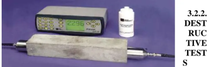
3.2.1b) Ultra sonic pulse velocity apparatus for the detection of cracks in the concrete
3.2.2. DEST RUC TIVE TEST S
In destructive test a sample is made and then destroyed to find out the strength of concrete. The destructive tests conducted on concrete are as follows:
a. Compressive strength test b. Tensile strength test c. Flexural strength test
The tests adopted in this study are only the destructive tests. These tests are done by using Universal Testing Machine (UTM).
3.3. OPERATION OF UTM
Apparatus: Universal testing machine, Test Specimen, Ruler etc.
Portrayal of UTM:
A machine intended to perform ductile, pressure, twist and shear tests, is called UTM. It predominantly comprises of two sections.
Loading Unit, control unit. Notwithstanding these units, there are sure frill like twisting TableNo.- , jaws for holding recorders and so forth.
Loading unit comprises of two crossheads i.e. upper cross head and lower cross head and a TableNo.- . System
i). Prepare a test example of no less than two feet.
ii). Measure caliper at any rate at three places and after that discover normal.
iii). Insert the reasonable No.- jaws in the hold and select an appropriate No.- heap scale on UTM.
vi). At a moment that the estimations of the heap by then this is called yield point.
vii). When the example breaks stop the machine.
viii). Note a definitive estimation of the heap.
3.4. Quality TESTS ON CONCRETE
3.4.1. COMPRESSIVE STRENGTH TEST
Out of many tests connected to the solid, this is the most extreme essential which gives a thought regarding every one of the qualities of cement. By this single test one judge that in the case of Concreting has been done legitimately or not. For solid shape test two sorts of examples either 3D squares of 15 cm X 15 cm X 15 cm or 10cm X 10 cm x 10 cm relying on the span of total are utilized. For the majority of the works cubical molds of size 15 cm x 15cm x 15 cm are regularly utilized.
Following are the system for Compressive quality trial of Concrete Cubes:
Device: Compression testing machine of limit.
Planning of Cube Specimens: The extent and material for making these test examples are from a similar cement utilized as a part of the field.
Blending: Mix the solid either by hand or in a research facility cluster blender.
Machine Mixing:
Mix the bond and fine total on a water tight none-retentive stage until the point when the blend is altogether mixed and is of uniform shading for ordinary cement, and to the concrete and sand include required extents of fly fiery debris and silica smolder are included for different blends.
Add the required extent of coarse total to all the blends until the point when the coarse total is consistently appropriated all through the bunch for all blends.
Add water and blend it until the point that the solid seems, by all accounts, to be homogeneous and of the coveted consistency to shape uniform blends.
Testing:
1. Clean the hills and apply oil.
2. Fill the solid in the molds in layers roughly 5cm thick.
3. Compact each layer with at the very least 35strokes for every layer utilizing a packing pole (steel bar 16mm distance across and 60cm long, shot pointed at bring down end)
4. Level the best surface and smoothen it with a trowel.
Curing:
The test examples are put away in clammy air for 24 hours and after this period the examples are stamped and expelled from the molds and kept submerged in clear crisp water until the point when taken out preceding test.
Strategy:
1. Remove the example from water after determined curing time and wipe out overabundance water from the surface.
2. Weigh the example on measuring machine.
3. Clean the bearing surface of the testing machine
4. Place the example in the machine in such a way, to the point that the heap should be connected to the inverse sides of the 3D square cast.
5. Align the example halfway on the base plate of the machine.
6. Rotate the mobile bit delicately by hand with the goal that it touches the best surface of the example.
7. Apply the heap bit by bit without stun and ceaselessly till the example falls flat
8. Record the greatest load and note any strange elements in the kind of disappointment.
(A) (B)
Fig–3.4.1 A) CONCRETE CUBE MOULD
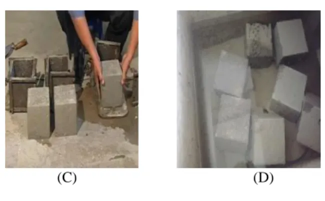
(C) (D)
Fig–3.4.1 C) DE MOULDING OF CUBE
Fig–3.4.1 D) CURING OF CUBE Note:
Minimum three specimens should be tested at each selected age. If the strength of any Specimen varies by more than 15 per cent of average strength, results of such specimen should be rejected. Average of three specimens gives the crushing strength of concrete.
2
Load in N
Compression Strength
Area in mm
Fig 3.4.1 E) Before
and after application of load by
Compression testing machine
Fig 3.4.1 F) Specimen after Testing in Compression testing machine
Table No.- 3.4.1a) Load details on the Compression specimen
Table No.- 3.4.1b) Compressive strength of M40 grades of concrete at 7,14 and 28 days
3.4.2. SPLIT TENSILE STRENGTH TEST Part Tensile Strength:
It is measured by testing chambers under polar pressure. Mechanical assembly: Compression testing machine, Test Specimen, Weighing balance, Ruler and so forth. Arrangement of Cylinder Specimens:
The chamber shape is of metal, 3mm thick. Each form is fit for being opened longitudinally to encourage the evacuation of the example and is furnished with a methods for keeping it shut while being used. The mean inside measurement of the form is 15 cm ± 0.2 mm and the stature is 30 ± 0.1 cm. Each shape is furnished with a metal base plate and form.
Machine blending is done in the lab bunch blender for regular cement and for every other sort of extents of fly fiery debris and silica rage concrete.
Compacting:
The test example ought to be made when practicable after the solid is filled into the shape in layers roughly 5 cm profound. Each layer is compacted either by hand or by vibration.
Compacted by hand:
The test example ought to be put away in a place at a temperature of 27° ± 2°C for 24 ±0.5 hrs After this period the example ought to be checked and expelled from the molds and quickly submerged in clean crisp water and kept there until taken out only preceding the test. The water in which examples are kept ought to be recharged each seven days and ought to be kept up at a temperature of 27° ± 2°c. The Concrete barrel is of 15 cm breadth and 30cm long.
Strategy:
i). Take the wet example from water after 7,14 and 28days of curing.
ii). Wipe out water from the surface of example.
iii). Draw polar lines on the two finishes of the example to guarantee that they are on the
same hub put.
iv). Note the weight and measurement of the example.
v). Set the pressure testing machine for the required range.
vi). Keep are plywood strip on the lower plate and place the example.
vii). Align the example so the lines set apart on the closures are vertical and loped over
the base plate.
viii). Place the other plywood strip over the example. ix). Bring down the upper plate to touch the plywood strip.
x). Apply the heap persistently without stun until the point when the example comes up short.
xi). Note down the breaking load (P).
Figuring:
The part rigidity is computed utilizing the recipeS p lit T e n s ile T e s t T s p, 2 P
D L Where P = applied load
D = diameter of the specimen L = length of the specimen
Therefore
2
D L P T s p
sExpected load P f
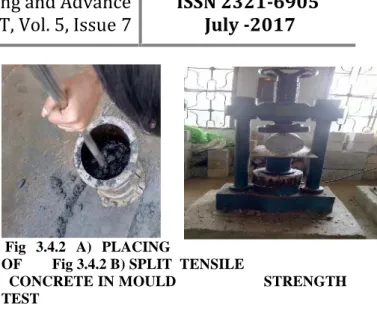
Fig 3.4.2 A) PLACING
OF Fig 3.4.2 B) SPLIT TENSILE
CONCRETE IN MOULD STRENGTH
TEST
Table No.- 3.4.2a) Load details on the Tensile specimen
Table No.- 3.4.2b) Tensile strength for M40 concrete
3.4.3. FLEXURAL STRENGTH TEST
It is the ability of a beam or slab to resist failure in bending. It is measured by loading un-reinforced 6x6 inch (150 x 150mm) concrete beams with a span three times the depth (usually 18 in.). The flexural strength is expressed as “Modulus of Rupture” (MR). Flexural MR is about 12 to 20 percent of compressive strength depending on the type, size and volume of coarse aggregate used. However, the best correlation for specific materials is obtained by laboratory tests for given materials and mix design.
Fig- 3.4.3 FLEXURAL STRENGTH TEST
Following are the procedure for Flexural strength test of Concrete Beams:
Apparatus:
Beam Breaking Machine (or) Universal Testing Machine (UTM) of capacity 40 tones, Test Specimen, Electronic weighing machine, Ruler etc.
1. Beam Moulds: Moulds used must be according to specification. In assembling the mould for use, the joints between the sections of the mould shall be thinly coated with mould oil and a similar coating of mould oil shall be applied between the contact surfaces of the bottom of the mould and the base plate in order to ensure that no water escapes during the filling. The interior faces of the assembled mould shall be thinly coated with mould oil to prevent adhesion of the concrete.
2. Tamping Bar: The tamping bar is a steel bar of 16 mm diameter, 60 cm long and bullet pointed at the lower end.
Calculation:
The flexural strength of the specimen shall be expressed as the modulus of rupture fs, which, if ‘a’
equals the distance between the line of fracture and the nearer support, measured on the centre line of the tensile side of the specimen, in cm, shall be calculated to the nearest 0.5 kg/sq cm as follows:
2
s
P
l
f
b
d
Where
b = measured width in cm of the specimen, d = measured depth in cm of the specimen at the
point of failure,
l = length in cm of the span on which the
specimen was supported, and
p = maximum load in kg applied to the
specimen.
If ‘a’ is less than 17.0 cm for a 15.0 cm specimen, or less than 11cm for a 10cm specimen, the results of the test shall be discarded
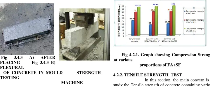
Fig 3.4.3 A) AFTER
PLACING Fig 3.4.3 B)
FLEXURAL
OF CONCRETE IN MOULD STRENGTH
TESTING
MACHINE
specimen
Table No.- 3.4.3 b) Flexural strength for M40 concrete
4. RESULT ANALYSIS
4.2 EFFECT OF FLY ASH & SILICA FUME 4.2.1. COMPRESSIVE STRENGTH
In this section, the main concern is to study the compressive strength of concrete containing various percentages of fly ash and silica fume in combination. Control specimens are concrete with 100% cement which is compared with the strength performance of concrete containing 30%, 40% of fly ash with 6% of silica fume.
Cubes with the size of 150 x 150 x 150 mm were tested at the ages of 7, 14 and 28 days. The results of the compressive strength test are shown in Table No.-6.4.1b). Where each value is averaged from the results of three cubes.
From the graph shown in the Fig.7.2.1., 30% and 40% replacement of fly ash with 6% silica fume has been observed as an optimal strength than other proportions at 7, 14 and 28 days.
Fig 4.2.1. Graph showing Compression Strength at various
proportions of FA+SF
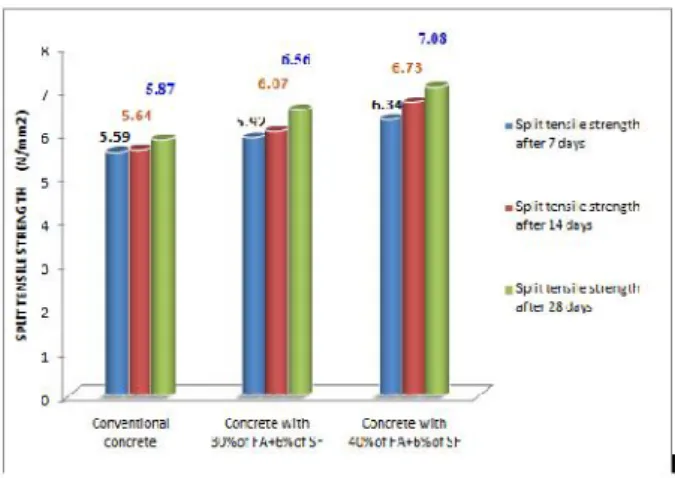
4.2.2. TENSILE STRENGTH TEST
Control specimens are concrete with 100% cement which is compared with the strength performance of concrete containing 30%, 40% of fly ash with 6% of silica fume. From the graph shown in the Fig.7.2.2., 30% and 40% replacement of fly ash with 6% silica fume has been observed as an optimal strength than other proportions at 7, 14 and 28 days.
Fig 4.2.2 Graph showing Tensile Strength at various proportions of FA+SF
FUTURE SCOPE
The development in concrete technology, supplementary cementations materials (SCM), also known as Admixtures, have been presented as substitutes for bond in concrete. A few sorts of materials are in like manner utilize, some of which are side-effects from other modern procedures, and consequently their utilization may have monetary points of interest. Be that as it may, the fundamental purpose behind their utilization is that they can give an assortment of valuable upgrades or changes to the solid properties
By fluctuating the blend extents, additionally examine works might be done around there.
By changing the admixture rate, the quality and sturdiness attributes can be contemplated
The study can be completed with shifting rate trade of the material for particular ease lodging applications
which are results from other mechanical procedures, and consequently their utilization may have monetary preferences.
However, the primary purpose behind their utilization is that they can give an assortment of valuable upgrades or adjustments to the solid properties.
The mechanical side-effects are utilized as admixture in concrete, To lessen the side-effect content in condition.
REFERENCES
[1] Amboise, J., Murat, M. and Pear J. (1985), Hydration Reaction and Hardening of Claimed Clays and Related Minerals: V. Extension of the Research and General Conclusions. Cement Concrete Res. 15, pp. 261–268.
[2] Hewlett, Peter (1998). Lea’s Chemistry of Cement and Concrete, Elsevier Butterworth Heinemann.
[3] IS 383-1970 Specification for fine and coarse aggregate from natural sources for concrete (Second revision).
[4] IS 456-2000, “Plain and Rein forced concrete” code of practice, Bureau Indian standards, New Delhi, India. [5] IS a 10262-2009 recommended guideline for concrete mix design, BIS, New Delhi, India, 2009. [6] Lea F.M (1970). The Chemistry of Cement and Concrete, 3rd Ed, Edward Arnold Ltd.
[7] Amphora, V.M. (1983). Fly Ash, Silica Fume, Slag, & Other Mineral By-product in Concrete, Publication SP-79, American Concrete Institute.
[8] Amphora, V.M. (1995). Characteristics of A Thermally Activated Alumina-silicate Pozzolanic Material and Its Use in Concrete, Cement Concrete Res 25: 1713–1725
[9] Marian, T., Pear, J. and Amboise J. (1992). The Action of Some Aggressive.
[10] Solutions on Portland and Claimed Late rite Blended Cement Concretes. Proceedings of the Fourth International Conference on Fly Ash, Silica Fume, Slag and Natural Pozzolans in Concrete, vol. I. Istanbul, Turkey.
[11] Neville, A.M. (1987). Concrete Technology. Longman Scientific & Technical.
[12] Pear, J. and Amorous, K. (1998) Development of Highly Reactive Met kaolin from Paper Sludge. Adv. Cement Based Material: 49–56
[13] Swami, R.N. (1986). Cement Replacement Materials, Surrey University Press:1-72.
[14] Indian Standard Specifications for Coarse and Fine Aggregates from Natural Sources for Concrete IS: 383-1970.
[15] Indian Standard Concrete mix Proportioning – Guidelines IS: 10262- 2009.
ACKNOWLEDGEMENT :
The Author would like to thank all the persons who helped in the completion of his experimental work. Also thanks are extended to ASR College of Engineering, Tanuku, INDIA for support throughout the execution of the experimental work.
AUTHORSBIOGRAPHY: