All Rights Reserved © 2012 IJARCSEE
115
PARAMETERS CHECKING BEFORE TAKE OFF
V.SRIDHAR
1P.SHREELA
2B.SRIKANTH
3T.SHIVAKRISHNA REDDY
41
Assistant Professor, ECE, Vidya Jyothi Institute of Technology, Hyderabad 2
Final year student, ECE, Vidya Jyothi Institute of Technology, Hyderabad 3
Final year student, ECE, Vidya Jyothi Institute of Technology, Hyderabad 4
Final year student, ECE, Vidya Jyothi Institute of Technology, Hyderabad
ABSTRACT:Now a day’s airplane is widely used vehicle. So it is very important to check the condition of the flight before it is take off. The main intension of this project is to check the fuel condition and temperature of the flight. According to this project whenever the temperature is high or fuel is low, the microcontroller display this information on LCD and intimate through buzzer.
In this paper the microcontroller plays a major role in transmitting data to RF transmitter and here the data is transmitted using RF communication. In transmitter side microcontroller directs the data obtained from PC and at the receiver side microcontroller receives the data from the RF receiver and given to robot. Here we are using temperature sensor to read the temperature value. If the temperature value crosses the threshold value then the given data is send to the controller to display on the PC which is on the section II through ADC.Fuel indicator with two levels, low level and medium level. This we can achieve as used in cars, the gauge consists of two parts: The sensing unit and The indicator The sensing unit usually uses a float connected to a potentiometer. Typically printed ink design in a modern automobile. As the tank empties, the float drops and slides a moving contact along the resistor, increasing its resistance. In addition, when the resistance is at a certain point, it will also turn on a "low fuel" light on some vehicles
Keywords: ADC,RF TRANSMITTER,PC,LCD,SENSING,MICRO CONTROLLER
I . INTRODUCTION TO EMBEDDED SYSTEM:
An embedded system is a special-purpose system in
which the computer is completely encapsulated by or dedicated to the device or system it controls. Unlike a general-purpose computer, such as a personal computer, an embedded system performs one or a few predefined tasks, usually with very specific requirements. Since the system is dedicated to specific tasks, design engineers can optimize it, reducing the size and cost of the product. Embedded systems are often mass-produced, benefiting from economies of scale.
Personal digital assistants (PDAs) or handheld computers are generally considered embedded devices because of the nature of their hardware design, even though they are more expandable in software terms. This line of definition continues to blur as devices expand. With the introduction of the OQO Model 2 with the Windows XP operating system and ports such as a USB port — both features usually belong to "general purpose computers", — the line of nomenclature blurs even more.
Physically, embedded systems ranges from portable devices such as digital watches and MP3 players, to large stationary installations like traffic lights, factory controllers, or the systems controlling nuclear power plants. In terms of complexity embedded systems can range from very simple with a single microcontroller chip, to very complex with
multiple units, peripherals and networks mounted inside a large chassis or enclosure.
All Rights Reserved © 2012 IJARCSEE
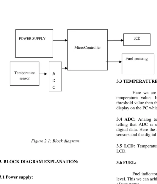
116 2. Block diagram:
Figure 2.1: Block diagram
3. BLOCK DIAGRAM EXPLANATION:
3.1 Power supply:
In this system we are using 5V power supply for microcontroller of Transmitter section as well as receiver section. We use rectifiers for converting the A.C. into D.C and a step down transformer to step down the voltage.
3.2 Microcontroller (8051):
In this project the microcontroller plays a major role in transmitting data to RF transmitter and here the data is transmitted using RF communication. In transmitter side microcontroller directs the data obtained from PC and at the receiver side microcontroller receives the data from the RF receiver and given to robot.
3.3 TEMPERATURE SENSOR:
Here we are using temperature sensor to read the temperature value. If the temperature value crosses the threshold value then the given data is send to the controller to display on the PC which is on the section II through ADC.
3.4 ADC: Analog to digital converter, the name itself is
telling that ADC is used for converting the analog data to digital data. Here the analog data is taken from the output of sensors and the digital data is given to the controller.
3.5 LCD: Temperature Variations will be displayed in the
LCD.
3.6 FUEL:
Fuel indicator with two levels, low level and medium
level. This we can achieve as used in cars, the gauge consists of two parts:
The sensing unit
The indicator
The sensing unit usually uses a float connected to a potentiometer. Typically printed ink design in a modern automobile. As the tank empties, the float drops and slides a moving contact along the resistor, increasing its resistance. In addition, when the resistance is at a certain point, it will also turn on a "low fuel" light on some vehicles.
4 SOFTWARE COMPONENTS:
Temperature sensor
A D C
MicroController
POWER SUPPLY LCD
All Rights Reserved © 2012 IJARCSEE
117 4.1 About Software:
Software’s used are:
Keil software for c programming
Express PCB for lay out design
Express SCH for schematic design
What's New in µVision3?
µVision3 adds many new features to the Editor like Text Templates, Quick Function Navigation, and Syntax Coloring with brace high lighting Configuration Wizard for dialog based startup and debugger setup. µVision3 is fully compatible to µVision2 and can be used in parallel with µVision2.
What is µVision3?
µVision3 is an IDE (Integrated Development Environment) that helps you write, compile, and debug
embedded programs. It encapsulates the following
components:
A project manager.
A make facility.
Tool configuration.
Editor.
A powerful debugger.
To help you get started, several example programs
(located in the \C51\Examples, \C251\Examples,
\C166\Examples, and \ARM\...\Examples) are provided.
HELLO is a simple program that prints the string
"Hello World" using the Serial Interface.
MEASURE is a data acquisition system for analog
and digital systems.
TRAFFIC is a traffic light controller with the RTX
Tiny operating system.
SIEVE is the SIEVE Benchmark.
DHRY is the Dhrystone Benchmark.
WHETS is the Single-Precision Whetstone
Benchmark.
Additional example programs not listed here are provided for each device architecture.
4.2 Building an Application in µVision2:
To build (compile, assemble, and link) an application in µVision2, you must:
1. Select Project
-(forexample,166\EXAMPLES\HELLO\HELLO.U
V2).
2. Select Project - Rebuild all target files or Build target.
µVision2 compiles, assembles, and links the files in your project.
4.3 Creating Your Own Application in µVision2 To create a new project in µVision2, you must:
1. Select Project - New Project.
2. Select a directory and enter the name of the project file.
3. Select Project - Select Device and select an 8051, 251, or C16x/ST10 device from the Device Database™.
4. Create source files to add to the project.
5. Select Project - Targets, Groups, Files. Add/Files, select Source Group1, and add the source files to the project.
6. Select Project - Options and set the tool options. Note when you select the target device from the Device Database™ all special options are set automatically. You typically only need to configure the memory map of your target hardware. Default memory model settings are optimal for most applications.
7. Select Project - Rebuild all target files or Build target.
4.4 Debugging an Application in µVision2
To debug an application created using µVision2, you must:
1. Select Debug - Start/Stop Debug Session.
2. Use the Step toolbar buttons to single-step through
your program. You may enter G, main in the Output
Window to execute to the main C function.
3. Open the Serial Window using the Serial #1 button on the toolbar.
Debug your program using standard options like Step, Go, Break, and so on.
4.5 Starting µVision2 and creating a Project
µVision2 is a standard Windows application and started by clicking on the program icon. To create a new project file select from the µVision2 menu.
Project – New Project…. This opens a standard
Windows dialog that asks you
for the new project file name.
We suggest that you use a separate folder for each project. You can simply use the icon Create New Folder in this dialog to get a new empty folder. Then select this folder and enter the file name for the new project, i.e. Project1. µVision2 creates a new project file with the name PROJECT1.UV2 which contains a default target and file group name. You can see these names in the Project.
Window – Files.
All Rights Reserved © 2012 IJARCSEE
118 micro controller you use. We are using for our examples the
Philips 80C51RD+ CPU. This selection sets necessary tool options for the 80C51RD+ device and simplifies in this way the tool Configuration.
4.6 Building Projects and Creating a HEX Files
Typical, the tool settings under Options – Target are all you need to start a new application. You may translate all source files and line the application with a click on the Build Target toolbar icon. When you build an application with syntax errors, µVision2 will display errors and warning messages in the Output Window – Build page. A double click on a message line opens the source file on the correct location in a µVision2 editor window. Once you have successfully generated your application you can start debugging
After you have tested your application, it is required to create an Intel HEX file to download the software into an EPROM programmer or simulator. µVision2 creates HEX files with each build process when Create HEX files under Options for Target – Output is enabled. You may start your PROM programming utility after the make process when you specify the program under the option Run User Program #1.
4.7 CPU Simulation
µVision2 simulates up to 16 Mbytes of memory from which areas can be mapped for read, write, or code execution access. The µVision2 simulator traps and reports illegal memory accesses.
In addition to memory mapping, the simulator also provides support for the integrated peripherals of the various 8051 derivatives. The on-chip peripherals of the CPU you have selected are configured from the Device.
Database selection
You have made when you create your project target. Refer to page 58 for more Information about selecting a device. You may select and display the on-chip peripheral components using the Debug menu. You can also change the aspects of each peripheral using the controls in the dialog boxes.
Start Debugging
You start the debug mode of µVision2 with the Debug – Start/Stop Debug Session command. Depending on the Options for Target – Debug Configuration, µVision2 will load the application program and run the startup code µVision2 saves the editor screen layout and restores the screen layout of the last debug session. If the program execution stops, µVision2 opens an editor window with the source text or shows CPU instructions in the disassembly window. The next executable statement is marked with a yellow arrow. During debugging, most editor features are still available.
For example, you can use the find command or correct program errors. Program source text of your application is shown in the same windows. The µVision2 debug mode differs from the edit mode in the following aspects. The ―Debug Menu and Debug Commands‖ described on page 28 are Available. The additional debug windows are discussed in the following
The paper structure or tool parameters cannot be modified. All build Commands are disabled.
Disassembly Window
The Disassembly window shows your target program as mixed source and assembly program or just assembly code. A trace history of previously executed instructions may be displayed with Debug – View Trace Records. To enable the trace history, set Debug – Enable/Disable Trace Recording.
If you select the Disassembly Window as the active window all program step commands work on CPU instruction level rather than program source lines. You can select a text line and set or modify code breakpoints using toolbar buttons or the context menu commands.
You may use the dialog Debug – Inline Assembly… to modify the CPU instructions. That allows you to correct mistakes or to make temporary changes to the target program you are debugging.
5. Steps for executing the Keil programs:
1. Click on the Keil uVision Icon on Desktop
All Rights Reserved © 2012 IJARCSEE
119
3. Click on the Project menu from the title bar
4. Then Click on New Project
5. Save the Project by typing suitable project name
with no extension in u r own folder sited in either C:\ or D:\
6. Then Click on save button above.
7. Select the component for u r project. i.e.
Atmel……
8. Click on the + Symbol beside of Atmel
9. Select AT89C51 as shown below
10. Then Click on “OK”
All Rights Reserved © 2012 IJARCSEE
120
12. Then Click either YES or NO………mostly
―NO‖
13. Now your project is ready to USE
14. Now double click on the Target1, you would get
another option ―Source group 1‖ as shown in
next page.
15. Click on the file option from menu bar and select
―new‖
16. The next screen will be as shown in next page,
and just maximize it by double clicking on its
blue boarder.
17. Now start writing program in either in ―C‖ or ―ASM‖
18. For a program written in Assembly, then save it
with extension ―. asm‖ and for ―C‖ based program save it with extension ― .C‖
19. Now right click on Source group 1 and click on
All Rights Reserved © 2012 IJARCSEE
121
20. Now you will get another window, on which by
default ―C‖ files will appear.
21. Now select as per your file extension given
while saving the file
22. Click only one time on option ―ADD‖
23. Now Press function key F7 to compile. Any
error will appear if so happen.
24. If the file contains no error, then press
Control+F5 simultaneously.
25. The new window is as follows
26. Then Click ―OK‖
27. Now Click on the Peripherals from menu bar,
and check your required port as shown in fig
below
28. Drag the port a side and click in the program
All Rights Reserved © 2012 IJARCSEE
122
29. Now keep Pressing function key ―F11‖ slowly
and observe.
30. You are running your program successfully
6. CONCLUSION:
The paper ―PARAMETER CHECKING
BEFORE TAKE OFF‖ has been successfully designed and
tested. Integrating features of all the hardware components used have developed it. Presence of every module has been reasoned out and placed carefully thus contributing to the best working of the unit. Secondly, using highly advanced IC’s and with the help of growing technology the paper has been successfully implemented.
7. REFERENCES:
1 WWW.MITEL.DATABOOK.COM
2 WWW.ATMEL.DATABOOK.COM
3 WWW.FRANKLIN.COM
4 WWW.KEIL.COM
Authors Biography:
VARADALA SRIDHAR is from HYDERABAD,
ANDHRAPRADESH.Completed M.TECH in ECE with
specialization (WIRELESS AND MOBILE
COMMUNICATION SYSTEMS) from JNTUH in 2011.he
has completed M.Sc (IT)from Nagarjuna University, guntur,
AndhraPradesh.and B.TECH in ECE from vidya jyothi
institute of technology affiliated by JNTUH in 2007.
Currently he is working as an Assistant professor in ECE department at Vidya Jyothi Institute of Technology, Hyderabad from 2010. he is having more than 3 years experience as an assistant professor. His areas of research
interests include Wireless and Mobile
communicationsystems,Digitalsignalprocessing,Imageproc essing,Telecommunications,communicationsystems, Signal
processing,Embedded systems. He has published 10
international journals papers.He is Lifetime Membership of ISTE, IETE.
P.SHREELA is from hyd, presently she is final year student of vidya jyothi institute of technology,aziz nagar,ECE branch. Her areas of research interests are include VLSI DESIGN, EMBEDDED SYSTEMS,AND COMMUNICATION SYSTEMS.
B.SRIKATH is final year student of vidya jyothi institute of technology, aziznagar, ECE branch. HIS areas of research interests are include VLSI DESIGN, EMBEDDED SYSTEMS, AND COMMUNICATION SYSTEMS.