A New Control Strategy For Cascaded H-Bridge Multilevel PV Inverter With Distributed
MPPT For Grid Connected Applications
Nagulapalli Trimurthulu1, M Sudheer Kumar2 M.Tech Student, Department of EEE, PCET,Anathavaram.1
Asst. Professor, Department of EEE, PCET,Anathavaram.2
Abstract-
-
A three - phase modular cascaded H-bridge multilevel inverter for a grid-connected photovoltaic (PV) system is presented in this project. To maximize the solar energy extraction of each PV string, an individual maximum power point tracking (MPPT) control scheme is applied, which allows the independent control of each dc-link voltage. PV mismatches may introduce unbalanced power supplied to the three-phase system. To solve this issue, a control scheme with modulation compensation is proposed. The three-phase modular cascaded multilevel inverter prototype has been built. A fuzzy controller is implemented in this project in the place of PI controller to balance the three phase grid current . Each H-bridge module is connected to a 185-W solar panel. Simulation results are presented to verify the feasibility of the proposed approach in MATLAB /SIMULINK environment.Key words — Cascaded multilevel inverter, distributed maximum power point (MPP) tracking (MPPT), modular, modulation compensation, photovoltaic (PV),Fuzzy controller
Introduction
DUE to the shortage of fossil fuels and environmental problems caused by conventional power generation, renewable energy, particularly solar energy, has become very popular. Solar-electric-energy demand has grown consistently by 20%–25% per annum over the past 20 years [1], and the growth is mostly in grid-connected applications. With the extraordinary market growth in grid-connected photovoltaic (PV) systems, there are increasing interests in grid-connected PV configurations. Five inverter families can
be defined, which are related to
different configurations of the PV system: 1) central inverters; 2) string inverters; 3) multi string inverters; 4) ac-module inverters; and 5) cascaded inverters [2]–[7]. The
configurations of PV systems are shown in Fig. 1. Cascaded inverters consist of several converters connected in series; thus, the high power and/or high voltage from the combination of the multiple modules would favor this topology in medium and large grid-connected PV systems [8]–[10]. There are two types of cascaded inverters. Fig. 1(e)
shows a
cascaded dc/dc converter connection of PV modules [11], [12]. Each PV module has its own particular dc/dc converter, and the modules with their related converters are as yet associated in arrangement to make a high dc voltage, which is given to a disentangled dc/air conditioning inverter. This approach joins parts of string inverters and air conditioning module inverters and offers the benefits of individual module most extreme power point (MPP) following (MPPT), however it is not so much expensive but rather more productive than air conditioning module inverters. In any case, there are two power transformation arranges in this design. Another cascaded inverter is appeared in Fig. 1(f), where each PV board is associated with its own particular dc/air conditioning inverter, and those inverters are then set in arrangement to achieve a high-voltage level [13]. This cascaded inverter would keep up the advantages of "one converter for every board, for example, better usage per PV module, capacity of blending diverse sources, and excess of the framework. What's more, this dc/air conditioning cascaded inverter expels the requirement for the per-string dc transport and the focal dc/air conditioning inverter, which additionally enhances the general proficiency. The particular cascaded H-connect multilevel inverter, which requires a disconnected dc hotspot for every H-connect, is one dc/air conditioning cascaded inverter topology. The different dc interfaces in the multilevel inverter influence autonomous voltage to control conceivable.
A New Control Strategy For Cascaded H-Bridge Multilevel PV Inverter With Distributed
MPPT For Grid Connected Applications
Nagulapalli Trimurthulu1, M Sudheer Kumar2 M.Tech Student, Department of EEE, PCET,Anathavaram.1
Asst. Professor, Department of EEE, PCET,Anathavaram.2
Abstract-
-
A three - phase modular cascaded H-bridge multilevel inverter for a grid-connected photovoltaic (PV) system is presented in this project. To maximize the solar energy extraction of each PV string, an individual maximum power point tracking (MPPT) control scheme is applied, which allows the independent control of each dc-link voltage. PV mismatches may introduce unbalanced power supplied to the three-phase system. To solve this issue, a control scheme with modulation compensation is proposed. The three-phase modular cascaded multilevel inverter prototype has been built. A fuzzy controller is implemented in this project in the place of PI controller to balance the three phase grid current . Each H-bridge module is connected to a 185-W solar panel. Simulation results are presented to verify the feasibility of the proposed approach in MATLAB /SIMULINK environment.Key words — Cascaded multilevel inverter, distributed maximum power point (MPP) tracking (MPPT), modular, modulation compensation, photovoltaic (PV),Fuzzy controller
Introduction
DUE to the shortage of fossil fuels and environmental problems caused by conventional power generation, renewable energy, particularly solar energy, has become very popular. Solar-electric-energy demand has grown consistently by 20%–25% per annum over the past 20 years [1], and the growth is mostly in grid-connected applications. With the extraordinary market growth in grid-connected photovoltaic (PV) systems, there are increasing interests in grid-connected PV configurations. Five inverter families can
be defined, which are related to
different configurations of the PV system: 1) central inverters; 2) string inverters; 3) multi string inverters; 4) ac-module inverters; and 5) cascaded inverters [2]–[7]. The
configurations of PV systems are shown in Fig. 1. Cascaded inverters consist of several converters connected in series; thus, the high power and/or high voltage from the combination of the multiple modules would favor this topology in medium and large grid-connected PV systems [8]–[10]. There are two types of cascaded inverters. Fig. 1(e)
shows a
Thus, individual MPPT control in each PV module can be accomplished, and the vitality collected from PV boards can be expanded. In the mean time, the measured quality and minimal effort of Multi level converters would position them as a prime possibility for the up and coming age of proficient, hearty, and dependable lattice associated sun based power hardware. A particular cascaded H-connect multilevel inverter topology for three-stage matrix associated PV frameworks is introduced in this venture. The board crisscross issues are routed to demonstrate the need of individual MPPT control, and a control conspire with appropriated MPPT control is then proposed. The circulated MPPT control plan can be connected to both single and three-stage frameworks.
. In addition, for the presented three-phase grid-connected PV system, if each PV module is operated at its own MPP, PV mismatches may introduce unbalanced power supplied to the three-phase multilevel inverter, leading to unbalanced injected grid current. To balance the three-phase grid current, modulation compensation is also added to the control system. A three-phase modular cascaded multilevel inverter prototype has been built. Each H-bridge is connected to a 185-W solar panel. The modular design will increase the flexibility of the system and reduce the cost as well. Simulation results are provided to demonstrate the developed control scheme. A modulation compensation scheme, which will not increase the complexity of the control system or cause extra power loss, is added to balance the grid current. Fuzzy controller is implemented in this project for the better regulation of the MPPT control of the proposed system and to balance the three phase grid current..
II. SYSTEM DESCRIPTION
Particular cascaded H-connect multilevel inverters for single and three-stage framework associated PV frameworks are appeared in Fig. 2. Each stage comprises of n H-connect converters associated in arrangement, and the dc connection of every H-scaffold can be encouraged by a PV board or a short string of PV boards. The cascaded multilevel inverter is associated with the framework through L channels, which are utilized to lessen the music in the current. By various mixes of the four switches in every H-connect module, three yield voltage levels can be produced: −vdc, 0, or +vdc. A cascaded multilevel inverter with n input sources will give 2n + 1 levels to integrate the air conditioner yield waveform. This (2n + 1)- level voltage waveform empowers the decrease of music in the integrated current, diminishing the measure of the required yield channels. Multilevel inverters additionally have different points of interest, for example, diminished voltage weights on semiconductor switches and having higher effectiveness when contrasted with other converter topologies [11].
stage inverter is mimicked in MATLAB/SIMULINK. Every H-connect has its own particular 185-W PV board associated as a detached dc source.
The PV board is demonstrated by the detail of the business PV board from A solid vitality CHSM-5612M. Consider a working condition that each board has an alternate light from the sun; board 1 has irradiance S =1000 W/m2, and board 2 has S = 600 W/m2. On the off chance that exclusive board 1 is followed and its MPPT controller decides the normal voltage of the two boards, the power removed from board 1 would be 133 W, and the power from board 2 would be 70 W, as can be found in Fig. 3. Without individual MPPT control, the aggregate power gathered from the PV framework is 203 W. In any case, Fig. 4 demonstrates the MPPs of the PV boards under the distinctive irradiance.
The greatest yield control esteems will be 185 and 108.5 W when the S esteems are 1000 and 600 W/m2, individually, which implies that the aggregate power gathered from the PV framework would be 293.5 W if individual MPPT can be accomplished. This higher esteem is around 1.45 times of the one preceding. Subsequently, individual MPPT control in each PV module is required to expand the productivity of the PV framework. In a three-stage lattice associated PV framework, a PV confuse may cause more issues. Beside diminishing the effectiveness ,this could even acquaint unequal power provided with the three-stage matrix associated framework. In the event that there are PV crisscrosses between stages, the information energy of each stage would be extraordinary. Since the framework voltage is adjusted, this distinction in input power will make lopsided current the lattice, which isn't permitted by matrix measures. For instance, to unbalance the current per stage over 10% isn't considered a few utilities, where the rate awkwardness is ascertained by taking the most extreme deviation from the normal current and separating it by the normal current [13]
Fig. 2. Topology of the modular cascaded H-bridge
multilevel inverter for grid-connected PV systems.
Fig. 4. P–V characteristic under the different irradiance
IV. CONTROL SCHEME
A. Distributed MPPT Control order to eliminate the adverse effect of the mismatches and increase the efficiency of the PV system, the PV modules need to operate at different voltages to improve the utilization per PV module. The separate dc links in the cascaded H-bridge multilevel inverter make independent voltage control possible. To realize individual MPPT control in each PV module, the control scheme proposed in [19] is updated for this application. The distributed MPPT control of the three-phase cascaded H-bridge inverter is shown in Fig. 5. In each H-H-bridge module, an MPPT controller is added to generate the dc-link voltage reference. Each dc-link voltage is compared to the corresponding voltage reference, and the sum of all errors is controlled through a total voltage controller that determines the current reference Idref. The reactive current reference Iqref can be set to zero, or if reactive power compensation is required, Iqref can also be given by a reactive current calculator [20], [21]. The synchronous reference frame phase-locked loop (PLL) has been used to find the phase angle of the grid voltage [22]. As the classic control scheme in three-phase systems, the grid currents in abc coordinates are converted to dq coordinates and regulated through proportional–integral (PI) controllers to
a2 to v d c are controlled individually through n−1 loops. Each voltage controller gives the modulation index proportion of one H-bridge module in phase a. After multiplied by the modulation index of phase a, n − 1 modulation indices can be obtained. Also, the modulation index for the first H-bridge can be obtained by subtraction. The control schemes in phases b and c are almost the same. The only difference is that all dc-link voltages are regulated through PI controllers, and n modulation index proportions are obtained for each phase .
Fig. 5. Control scheme for three-phase modular cascaded
H-bridge multilevel PV inverter.
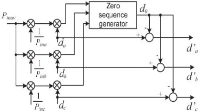
B. Modulation Compensation
As mentioned earlier, a PV mismatch may cause more problems to a three-phase modular cascaded H-bridge multilevel PV inverter. With the individual MPPT control in each H-bridge module, the input solar power of each phase would be different, which introduces unbalanced current to the grid. To solve the issue, a zero sequence voltage can be imposed upon the phase legs in order to affect the current flowing into each phase [25], [26]. If the updated inverter output phase voltage is proportional to the unbalanced power, the current will be balanced. Thus, the modulation compensation block, as shown in Fig. 6, is added to the control system of three-phase modular cascaded multilevel PV inverters. The key is how to update the modulation index of each phase without increasing the complexity of the control system.
Fig. 6. Modulation compensation scheme.
First, the unbalanced power is weighted by ratio r j, which is calculated as
r = (1)
where Pinj is the input power of phase j (j = a, b, c), and
Pinav is the average input power.
Then, the injected zero sequence modulation index can be generated as
where dj is the modulation index of phase j (j = a, b, c) and is determined by the current loop controller. The modulation index of each phase is updated by
d′ = d − d (3)
Only simple calculations are needed in the scheme, which will not increase the complexity of the control system. An example is presented to show the modulation compensation scheme more clearly. Assume that the input power of each phase is unequal
P = 0.8 P = 1 P = 1 (4)
V. FUZZY CONTROLLER
The word Fuzzy means vagueness. Fuzziness occurs when the boundary of piece of information is not clear-cut. In 1965 Lotfi A. Zahed propounded the fuzzy set theory. Fuzzy set theory exhibits immense potential for effective solving of the uncertainty in the problem. Fuzzy set theory is an excellent mathematical tool to handle the uncertainty arising due to vagueness. Understanding human speech and recognizing handwritten characters are some common instances where fuzziness manifests.
Fuzzy set theory is an extension of classical set theory where elements have varying degrees of membership. Fuzzy logic uses the whole interval between 0 and 1 to describe human reasoning. In FLC the input variables are mapped by sets of membership functions and these are called as
“FUZZY SETS”.
Fuzzy set comprises from a membership function which could be defines by parameters. The value between 0 and 1 reveals a degree of membership to the fuzzy set. The process of converting the crisp input to a fuzzy value is called as
“fuzzificaton.” The output of the Fuzzier module is
interfaced with the rules. The basic operation of FLC is constructed from fuzzy control rules utilizing the values of fuzzy sets in general for the error and the change of error and control action. Basic fuzzy module is shown in fig.6. The results are combined to give a crisp output controlling the output variable and this process is called as
Fig.7. Fuzzy Basic Module
Fuzzy rules
In the fuzzy control, input and output variables are the size of the form to describe in words, so to select special vocabulary to describe these variables, generally used in "big, medium and small" Three words to express the controller input and output variables state, plus the positive and negative directions, and zero, a total of seven words : { negative big, negative medium, negative small, zero, positive small, middle, CT } , the general terms used in the English abbreviation prefix : {NB , NM, NS , ZE, PS , PM, PB}.
COE
E
NB NM NS ZE PS PM PB
NB NB NB NB NB NM NS ZE
NM NB NB NB NM NS ZE PS
NS NB NM NS NS ZE PS PM
ZE NB NM NS ZE PB NS ZE
PS NM NS ZE PS PM PM PB
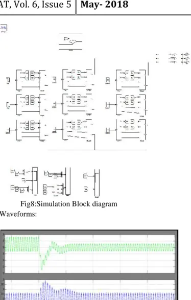
Fig8:Simulation Block diagram Waveforms:
Fig. 11. DC-link voltages of phase b with distributed MPPT (T = 25◦C).
Fig. 12. Power extracted from PV panels with distributed MPPT.
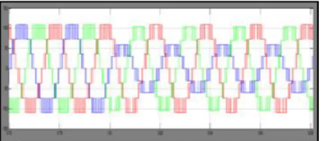
Fig. 13. Three-phase inverter output voltage waveforms with modulation compensation.
Fig. 14. Three-phase grid current waveforms with modulation compensation.
VI. CONCLUSION
In this project, a modular cascaded H-bridge multilevel inverter for grid-connected PV applications has been
presented. The multilevel inverter topology will help to improve the utilization of connected PV modules if the voltages of the separate dc links are controlled independently. Thus, a distributed MPPT control scheme for both single- and three-phase PV systems has been applied to increase the overall efficiency of PV systems. For the three-phase grid-connected PV system, PV mismatches may introduce unbalanced supplied power, resulting in unbalanced injected grid current. A modulation compensation scheme, which will not increase the complexity of the control system or cause extra power loss, is added to balance the grid current. Fuzzy controller is implemented in this project for the better regulation of the MPPT control of the proposed system and to balance the three phase grid current. With the proposed control scheme, each PV module can be operated at its own MPP to maximize the solar energy extraction, and the three-phase grid current is balanced even with the unbalanced supplied solar power.
REFERENCES
[1] Bailu Xiao, Student Member, IEEE, Lijun Hang, Member, IEEE, Jun Mei, Member, IEEE, Cameron Riley, Student Member, IEEE, Leon M. Tolbert, Cascadedow, IEEE, and Burak Ozpineci,Senior Member, IEEE”Modular Cascaded H-Bridge Multilevel PV Inverter With Distributed MPPT for Grid-Connected Applications”
[2] J. M. Carrasco et al., “Power-electronic systems for the grid integration of renewable energy sources: A survey,” IEEE Trans. Ind. Electron., vol. 53, no. 4, pp. 1002–1016, Jun. 2006.
[3] S. B. Kjaer, J. K. Pedersen, and F. Blaabjerg, “A review of single-phase grid connected inverters for photovoltaic modules,”IEEE Trans. Ind. Appl., vol. 41, no. 5, pp. 1292– 1306, Sep./Oct. 2005.
[4] M. Meinhardt and G. Cramer, “Past, present and future of grid connected photovoltaic- and hybrid power-systems,” in Proc. IEEE PES Summer Meet., 2000, vol. 2, pp. 1283– 1288.
[5] M. Calais, J. Myrzik, T. Spooner, and V. G. Agelidis, “Inverter for singlephase grid connected photovoltaic systems—An overview,” inProc. IEEE PESC, 2002, vol. 2, pp. 1995–2000.
[7] B. Liu, S. Duan, and T. Cai, “Photovoltaic DC-building-module-based BIPV system—Concept and design considerations,”IEEE Trans. Power Electron., vol. 26, no. 5, pp. 1418–1429, May 2011.
[8] L. M. Tolbert and F. Z. Peng, “Multilevel converters as a utility interface for renewable energy systems,” in Proc. IEEE Power Eng. Soc. Summer Meet., Seattle, WA, USA, Jul. 2000, pp. 1271–1274.
[9] H. Ertl, J. Kolar, and F. Zach, “A novel multicell DC– AC converter for applications in renewable energy systems,” IEEE Trans. Ind. Electron., vol. 49, no. 5, pp. 1048–1057, Oct. 2002.
[10] S. Daher, J. Schmid, and F. L. M. Antunes, “Multilevel inverter topologies for stand-alone PV systems,” IEEE Trans. Ind. Electron., vol. 55, no. 7,pp. 2703–2712, Jul. 2008.
[11] G. R. Walker and P. C. Sernia, “Cascaded DC–DC converter connection of photovoltaic modules,”IEEE Trans. Power Electron., vol. 19, no. 4, pp. 1130–1139, Jul. 2004.
[12] E. Roman, R. Alonso, P. Ibanez, S. Elorduizapatarietxe, and D. Goitia, “Intelligent PV module for grid-connected PV systems,”IEEE Trans. Ind. Electron., vol. 53, no. 4, pp. 1066–1073, Jun. 2006.