Broad Lane, Sheffield, S3 7HQ Telephone: +44 (0)114 289 2000 Facsimile: +44 (0)114 289 2500
Risk Based Inspection
-A Case Study Evaluation of Onshore Process Plant
HSL/2002/20
W Geary PhD MIM CEng
Project Leader: W Geary
Summary
Objectives
Risk based inspection (RBI) as a method for prioritising the inspection of plant has received considerable attention over the last few years and methods have been developed nationally, for example by the American Petroleum Institute (API) and by a number of private
organisations, particularly in the petrochemical industry. A co-ordinated approach to these developments is currently underway in Europe (RIMAP).
A survey of approximately 50 UK organisations carried out by HSL in 1999 showed that approximately half were using an approach to plant inspection based on risk. It was clear however, that a wide range of systems were in use including commercial software packages and in-house systems specific to individual plants. Given the disparate nature of some of these systems and the likelihood that RBI assessments might produce very different results
depending on which methodology was used, HSE took the view that a study should be
undertaken using a number of example cases to tease out the differences between the systems. This is the subject of the current investigation. The work (Programme JR32082) has been jointly funded by HSE’s Technology Division (TD) and the Hazardous Installations
Directorate (HID). The programme was essentially in two parts. Firstly, a case study round robin was undertaken by HSL, the subject of this report, and secondly, a review of European developments has been carried out by Mitsui Babcock Technology, the details of which are reported in Reference 8.
Main Findings
1 Considerable variation in the selection of damage mechanisms for assessment was apparent.
2 Pre-sifting of damage mechanisms, thought to be inactive, had occurred.
3 Significant variability was found in the assignment of the importance of damage mechanisms; different conclusions, regarding the activity of a damage mechanism, were drawn from identical data.
4 Where software systems were used and calculations of the consequences were made, it was not transparent what assumptions had been made; details were frequently hidden in the “black box”.
5 Assumptions made about nearby plant and the likely occupancy by plant personnel together with the differences in the definitions of equipment, production and business were not
transparent.
6 A number of the RBI methods considered the likelihood and consequences independently. The method has the benefit of simplicity and ensures conservatism but lacks the accuracy of systems where the consequences are assessed separately for each damage mechanism.
7 In some cases RBI systems averaged the individual consequences associated with health and safety, business and plant issues and environmental factors to generate an overall conse-quence factor. Thus it appears possible that plant judged to have, for example, high safety consequences could be assessed as having medium overall consequences. From HSE’s view-point this might require some justification.
8 Inspection plans were based on the assessment of the damage mechanisms and the assessed risk and consequently there were significant differences in both the content of the proposed inspections and in the inspection period.
9 In most cases inspection plans only included procedures for damage mechanisms regarded as active. There was evidence, in a smaller number of plans, of procedures explicitly included for inactive or “unlikely” mechanisms.
10 The HSE best practice document suggests that for high consequence plant sample checks for unanticipated mechanisms would be beneficial, however, little sample checking or speculative inspection was proposed by the participants.
11 Given the diversity of views on active damage mechanisms, some speculative inspection would, arguably, be desirable.
12 Use of existing guidance on inspection periodicity was made by all the participants and included reference to IP 12 and 13 (5,6), SAFed (2) and API 510 (4) documents. Inspection intervals were, therefore, limited to half remnant life in many cases.
13 The participants did not set limits to inspection periods based on the existing or historical periods for the vessel under examination.
14 Subjective judgements based on limited information did lead to some significant differences in inspection periods.
15 Generally, the inspection periods reflected the assessed risk. Nevertheless considerable scatter was apparent in the data and some participants exhibited greater conservatism in their assessments than others.
Main Recommendations
1 The reporting and assessment of damage mechanisms lacks transparency (presifting), some additional guidance to users would be useful.
2 Software, expert systems and expert judgement all have merits, greater integration of these elements might be beneficial.
3 A review of how damage mechanisms are treated based on uncertain data would increase confidence in the approach.
5 Transparency is needed in the assessment of consequences particularly with respect to the assumptions that are made.
6 Inspection planning guidance may be useful particularly for speculative inspections and sample checks for high consequence plant.
CONTENTS 1. INTRODUCTION 1 2. THE PARTICIPANTS 1 3. CASE STUDIES 1 4. METHODOLOGIES 2 4.1 Participant A 2 4.2 Participant B 3 4.3 Participant C 3 4.4 Participant D 4 5.5 Participant E 5 4.6 Participant F 6 4.7 Participant G 7 5. EVALUATIONS 8
5.1 CASE 1 Molecular Sieve 8
5.1.1 Participant A 8 5.1.2 Participant B 11 5.1.3 Participant C 11 5.1.4 Participant D 11 5.1.5 Participant E 12 5.1.6 Participant F 14 5.1.7 Participant G 15 5.1.8 Summary 15 5.1.8.1 Likelihood 15 5.1.8.2 Consequences 17 5.1.8.3 Risk 17
5.1.8.4 Inspection Plan and Period 18
5.2 Case 2 Distilate Hydrotreater 19
5.2.1 Participant E 19 5.2.2 Participant F 19 5.2.3 Participant C 20 5.2.4 Summary 20 5.2.4.1 Likelihood 20 5.2.4.2 Consequences 21
5.2.4.3 Inspection Plan and Period 21
5.3.1 Participant B 21 5.3.2 Participant A 22 5.3.3 Participant F 23 5.3.4 Participant E 23 5.3.5 Participant C 24 5.3.6 Summary 24 5.3.6.1 Likelihood 24 5.3.6.2 Consequences 25 5.3.6.3 Risk 25
5.3.6.4 Inspection Plan and Period 26
5.4 Case 4 Methanol Storage Drum 26
5.4.1 Participant F 26 5.4.2 Participant E 27 5.4.3 Participant C 27 5.4.4 Summary 27 5.4.4.1 Likelihood 27 5.4.4.2 Consequences 27
5.4.4.3 Risk, Inspection Plan and Periodicity 27
6. DISCUSSION 28
6.1 Introduction 28
6.2 Likelihood analysis 29
6.3 Consequences and Risk 29
6.4 Inspection Plan and Period 30
6.4.1 Mitsui Babcock review of inspection recommendations 31
7. CONCLUSIONS 33
8. RECOMMENDATIONS FOR FURTHER WORK 34
9. REFERENCES 35
Appendix 1 Data Requirements Appendix 2 Case 1 Molecular Sieve Appendix 3 Case 2 Distilate Hydrotreater Appendix 4 Case 3 Autoclave
Appendix 5 Case 4 Methanol Storage Drum
Appendix 6 Case 1 Mol. Sieve additional information Appendix 7 Case 1 Mol. Sieve additional information 2
1 INTRODUCTION
Risk based inspection (RBI) as a method for prioritising the inspection of plant has received considerable attention over the last few years and methods have been developed nationally, for example by the American Petroleum Institute (API) and by a number of private
organisations, particularly in the petrochemical industry. A co-ordinated approach to these developments is currently underway in Europe (RIMAP).
A survey of approximately 50 UK organisations carried out by HSL in 1999 (1) showed that approximately half were using an approach to plant inspection based on risk. It was clear however, that a wide range of systems were in use including commercial software packages and in-house systems specific to individual plants. Given the disparate nature of some of these systems and the likelihood that RBI assessments might produce very different results
depending on which methodology was used, HSE took the view that a study should be
undertaken using a number of example cases to tease out the differences between the systems. This is the subject of the current investigation. The work (Programme JR32082) has been jointly funded by HSE’s Technology Division (TD) and the Hazardous Installations
Directorate (HID). The programme was essentially in two parts. Firstly, a case study round robin was undertaken by HSL, the subject of this report, and secondly, a review of European developments has been carried out by Mitsui Babcock Technology, the details of which are reported in Reference 8.
2. THE PARTICIPANTS
A number of organisations known, as a result of the survey work carried out earlier or by the project steering committee, to be actively involved in the use or development of RBI were contacted and asked to participate in a round robin exercise using a number of specifically prepared case studies. Organisations across a range of industrial sectors were contacted. Positive responses were received from most and those who agreed to provide case study information or to participate in the assessments are shown in Table 1.
Table 1 shows that about half of the participants were directly involved in petrochemical operations and a number of the other organisations provide consultancy to the petrochemical industry. Greater participation from other industrial sectors would have provided useful data on the implementation of RBI outside the petrochemical industry, however, the cross section of those who agreed to take part probably reflects the extent to which RBI is being developed and used across all industrial sectors in the UK. This bias towards the petrochemical industry is also reflected in the fact that three of the four case studies, provided by the participating organisations, are petrochemical industry based.
The participants are referred to by an identification letter in this report to preserve confidentiality.
3. CASE STUDIES
Each of the participants was asked if they would be willing to provide a case studyfor the programme. As a result, 4 case studies were developed, provided by 3 organisations. The cases took some time to develop and in some instances were completed too late to be
circulated to all participants. Table 2 shows which case studies were circulated to each of the participants.
Case study data was requested in a format similar to that required for analysis using the API methodology. An example of the data requirements is shown in Appendix 1. Some general background information was requested together with specific information in 10 categories relating to likelihood assessments and 8 relating to consequences. Once a complete set of data had been prepared participants were circulated with the information and asked to undertake an analysis. Participants were asked to request additional information if the data provided in the cases was insufficient to carry out their assessments.
The case studies prepared consisted of a molecular sieve (Appendix 2), a distillate hydrotreater (Appendix 3), an autoclave (Appendix 4), and a methanol storage drum (Appendix 5).
The intention of the work was to obtain some quantifiable measure of the output of the RBI process thus participants were specifically requested to provide analysis on the risk, a proposed inspection plan and inspection periodicity. Inspection planning is considered in Section 6.4 and additional discussion has been provided by Mitsui Babcock and is included in that Section.
It was not intended as part of this exercise to evaluate the feedback and integrity management audit systems.
A draft of this report, detailing the findings of the round robin exercise, was circulated to participants for their comments. Detailed comments were received from two participants and these have been incorporated into the final version of the report.
4. METHODOLOGIES
As part of the case study exercise discussions were held with each of the participants and some details of the RBI procedures were obtained. The following sections give a general outline of the approaches adopted and include comments and views of the participants, when expressed.
4.1 Participant A
Risk assessments are carried out using a manual, qualitative approach by a RBI review team composed of plant personnel with appropriate skills, experience and from a range of
disciplines. A standard 5 x 5 matrix, an example of which is shown in Figure 1, is used to establish the level of risk.
The probability of failure is qualitatively estimated on a five box scale from highly unlikely to highly probable. This is quantified in different ways according to the degradation mechanism under consideration, for example, for corrosion “highly unlikely” is defined as a remaining life of greater than 10 years and “highly probable” is defined as the allowable corrosion loss is used up. For fatigue the equivalent descriptors are highly unlikely: not considered significant and highly probable: remnant operating life less than 60% of design life. For mechanisms such as SCC and hydrogen cracking, highly probable is interpreted as meaning widespread cracking in similar vessels.
Consequence is assessed on a five box scale from very low to very high. Six contributory factors to consequence are assessed: impact on production, personnel, equipment, fluid
characteristics, fluid hazard contents and fluid pressure. Each of these are assessed on a scale of 3 or 4 and a summation of the consequence factors gives the overall consequence rating. Inspection planning is agreed by the RBI review team on the basis of the evaluation of the degradation mechanisms, the previous inspection history and the assessment of risk.
4.2 Participant B
RBIanalysis is carried out by a team of specialists with relevant knowledge and experience of the plant. Specialisms need to include operational and maintenance, process, structural design, failure mechanisms and inspection functions.
Assessments are made on a qualitative basis with probability and consequence being evalu-ated on a scale of 1 to 4. Consequence is assessed for each of the damage mechanisms on the basis of safety, health and environment, business issues and equipment costs. The risk is then calculated, for each damage mechanism, based on the sum of the consequence factors under each heading multiplied by the probability factor. The analysis is based on the judgement of the RBI team. There appeared to be little written guidance to assist in the analysis.
The inspection periodicity is assessed on some fraction of remaining life and depends upon consequence information. Inspection procedure guidelines, details of technique limits and reliability are available to the analyst.
A view was expressed that RBI was appropriate for continuous process plant but that the benefits were limited for plant where batch processing predominated.
4.3 Participant C
The RBI analysis conducted by this participant is primarily on offshore plant.
Offshore assessments are different, in some respects, to those carried out on onshore refinery plant. Offshore oil and gas production is characterised by: a) changing production profile since oil and gas production diminish with time; b) increasing water production and increase in other components such as sand, CO2 and H2S with time; c) introduction of new fluids from other oil or gas reservoirs; d) modifications to plant using different materials in response to changing conditions (more or less aggressive environments).
Pressure systems are required to undergo an integrity review of all the factors which may affect the condition of the plant. The analysis is required to ensure that the RBI programme remains valid and the appropriate inspection methods, risk ratings and intervals are correctly specified. Criticality is determined using the conventional likelihood – consequence matrix. Plant is graded, taking into account criticality assessment results, and the gradings are used to select the inspection intervals based on a knowledge of plant condition and operating
environment. Knowledge of in-service behaviour must be reliable to justify inspection intervals. Equipment may be allocated a Grade between 0 and 3 based on the number of previous inspections and the rate and predictability of deterioration based on the Institute of Petroleum guidance on the examination of pressure vessels and piping (5, 6). Grade 0 is allocated where: a) there is insufficient evidence or knowledge of operational effects on which to predict in-service behaviour, b) the rate of deterioration is potentially rapid and, c) the rate
of deterioration is unpredictable. Grade 3 is allocated where: a) at least one thorough
examination at Grade 0 and one examination at either Grade 1 or 2 have been carried out, b) a low and predictable rate of deterioration is known and, c) sufficiently reliable evidence of a negligible rate of deterioration in a stable service environment such that an increased inspection interval is justified.
The inspection intervals take account of the uncertainty associated with service duty such that examination takes place sufficiently well in advance of any potential failure to ensure that loss of containment is minimised.
The intervals are obtained from a matrix of criticality rating and the inspection grade moderated by a maximum review period if, for example, there are additional statutory or British Standard requirements, an example of the matrix is shown in Table 3. Additionally, if time based deterioration occurs (corrosion or creep) then the half life applies. Inspection and engineering judgement may reduce inspection periods if equipment operation warrants it. The review examination, with limited physical examination, is used to confirm information
regarding the allocation of the inspection grade and to confirm that the inspection interval remains applicable.
Where groups of items are substantially the same with regard to geometry, design,
construction and service conditions and similar deterioration mechanisms can reasonably be expected, sample examinations can be applied. Sampling may commence at the second examination following a period at Grade 0 but no item within the group should exceed the maximum interval recommended for Grade 3. Should the examination of the sample give unacceptable results then all items within the group become due for immediate inspection. Limits are set on the sample size such that, for groups containing 5 to 8 items, 2 must be inspected and, for 9 or more items, 3 must be inspected.
4.4 Participant D
Compliance with current API 510 (Pressure vessel inspection code: maintenance, inspection, rating, repair, and alteration (1997)) requires that pressure vessels are inspected at a maximum interval of 10 years. In addition, plant shutdown periods are scheduled at 5 yearly intervals and thus the scope for extending or reducing inspection periodicity by using RBI arguments is severely limited.
Nevertheless RBI may be used under some circumstances and a commercial software system is currently used for RBI analysis. A review team compile and consider the plant asset data prior to using the software. The software requires likelihood input data for: design pressure and temperature, operating pressure and temperature, diameter and length, material, thinning factor, stress corrosion cracking (SCC) factor, H2 partial pressure, service life, number of inspections, inspection effectiveness (4 point scale), corrosion rate, corrosion allowance and online monitoring. Inspection effectiveness can be assessed independently for each of the degradation mechanisms. This data produces a likelihood category.
Consequence assessment is made on a 5 point scale (A to E) and includes the following: representative fluid, toxic percentage, inventory, detection and isolation systems. The output from the consequence analysis is an equipment damage area, toxicity area, fatality area and a consequence area. The software does not provide for the analysis of commercial
degradation mechanisms are not covered and this makes its use limited to certain types of plant, presumably by design. Written guidance in the form of a resource document is provided to assist the user with input data. The likelihood and consequence data are combined to
produce a risk ranking on a 5 x 5 risk matrix.
In the event of plant being assessed as high risk an action plan is initiated. An action plan team is formed from corrosion, inspection, process, operations, safety and maintenance functions. Options are considered to reduce the risk either by inspection and re-evaluation or by changes to operational parameters, for example, limiting pressure or temperature or by controlling feedstock to limit damage mechanisms. If inspection is the preferred option then the review team consider inspection history, degradation mechanisms, inspection methods and plant conditions. An inspection plan is developed covering the methods to be used, the areas to be covered and the frequency. The inspection interval is assessed on the basis of the previous inspection history and is limited to half the remaining life, where the life is defined as the time for degradation to reach a limiting size. These assessments are based primarily on guidance in API 510 (4) and on the professional judgement of the review team.
4.5 Participant E
Three assessment methods are available and their use depends on the size and complexity of the plant to be assessed. The first method relies primarily on the use of expert judgements obtained from a carefully composed review team. The second is a rule based approach which is software based and the third is a fully quantitative analysis method used primarily for plant identified as high risk.
In practice the first two methods are generally used together. The value of combining the judgmental method and the rule based method is to pick up issues that might otherwise be missed. For example, although a review team might come to the conclusion that, say,
corrosion was not a major damage mechanism the rule based software system would perform the analysis. Conversely the rule based system may not be sufficiently flexible to pick up some degradation mechanisms that might result from, for example, the products of decomposition and therefore the review team provides essential input.
Assessments are carried at one of three levels depending on the risk. Level 1 is essentially a risk ranking procedure. At level 2 all the damage mechanisms are considered and the worst case consequences are considered. At level 3 the individual consequence - likelihood combinations for each feature of the plant are assessed which produces finer risk resolution. The level 3 assessments are primarily based on expert judgement but quantitative methods are used where appropriate. The likelihood of damage is assessed using information from
previous inspections and an assessment of the effectiveness of the inspections (rated from poorly effective to very effective) for each of the damage mechanisms is obtained.
Consequence modelling at level 3 requires data on the following: the process stream, stream phase, temperature, pressure, inventory, and material density. Further information is required on: the area of the plant; plant population; local population density; weather conditions including temperature and pressure; safety, business and environmental data (these include distances to office blocks, boundary fences, water courses etc.); repair time; other impacts on production; containment bunding; isolation facilities; remotely operated valves and
blowdown; fire protection; gas and fire detection; evacuation and safe refuge; water monitors; deluge system; foam fire fighting; on site fire brigade and equipment redundancy. Hazard
areas (in square metres) are calculated for the impact on personnel and the equipment (sub-divided into flammable, toxic, pool fire and overpressure areas). Thus a consequence ranking can be generated for safety, business and environment.
Inspection planning is carried out by the review team on the basis of expert judgement. Each mechanism is considered and judgements are made on the appropriate technique and
coverage.
The inspection periodicity is derived from a matrix of the risk and a confidence index which is based on the Inspection Grade concept described in IP 12 and 13 (5,6). The confidence index is based on expert judgement, and is derived from previous inspections which are used to validate previous risk assessment findings. A rule set is provided to guide users. Thus the process is partly automated and partly objective. In any event the inspection interval cannot be set beyond a particular fraction of the remnant life, which is based on risk1. It should be noted that items which have a very short remnant life, also have a low confidence factor, and hence have very short maximum (capped) inspection intervals.
4.6 Participant F
This system is essentially an implementation of the methodology described in API 581 (2). The approach is semi-quantitative with separate calculations being performed for the
likelihood and consequence components for each item of plant. The results are reported on a 5 x 5 matrix with the likelihood category of 1 to 5 and the consequence category A to E. Thus, the lowest risk category is 1A and the highest risk category 5E.
Likelihood analysis is based on the assessment of each of the damage mechanisms and a probability of failure can be determined from the product of a generic failure frequency, the damage factor (based on known degradation rates) and a management factor. The
management factor is based on guidance in API 581 Appendix D and covers areas including leadership and administration, management of change, operating procedures, safe working practices and training. For mechanisms where data is limited, the guidance in the API technical modules is used. The damage factor for any given mechanism is in turn dependent on the effectiveness of the inspection for that mechanism. Bayes theorem is used to derive a quantitative inspection effectiveness value from a qualitative inspection category. Thus for a fairly effective inspection procedure (the true damage state is correctly identified 50% of the time) the damage factor and thus the probability of failure increase. A quantitative evaluation of the likelihood of failure in terms of events per year can thus be obtained.
Consequence analysis is based on knowledge of the equipment damage, fatality and toxicity areas, the number of outage days together with generic cost data. Typical examples are: equipment cost (per square m): £6k, population density (per square m): 0.001, injury cost per person: £600k - £6M (fatality costs are typically assigned a value of £6M), outage costs (per day): £60k. Worst case scenario data can be used with equipment damage costs of £300M and 10 fatalities. Allowance can be made for larger consequence events where litigation and fines may be an issue and are accounted for within the code. Consequence data are calculated for a range of hole sizes and weighted based on generic data for the failure frequency for each hole size and the total failure frequency for the equipment item.
1 20% for risk rank 1; 30% for risk rank 2; 50% for risk rank 3; 75% for risk rank 4 and 100% for risk rank 5.
Risk tolerability criteria are established for each case based on financial and safety risks together with other influences such as applicable regulations, local sensitivities and the legal environment. These criteria establish a target risk level.
The methodology then requires a future risk evaluation target to be set by the user. The inspection effort needed to reduce the risk to the target risk level can then be calculated. Threshold values on likelihood and total cost risk are used and an inspection interval is set on this basis following the guidance in API 510 (4). The data can then be reviewed and modified by the user. Account can be taken of the time dependency of damage mechanisms in the risk assessment by considering, for example, crack growth rates and how well the degradation has been tracked by the inspection programme.
4.7 Participant G
A semi-quantitative software based system has been developed in-house and is generally aligned with the API 581 recommendations. The software system, based on a corporate RBI manual which details the methodology, is used in conjunction with a plant RBI team
consisting of a materials and corrosion engineer, plant inspector, process technologist, plant operator and maintenance engineer. The RBI system consists of a plant integrity database, a risk assessment procedure and an inspection planning procedure. Monitoring, inspection and repair data are reviewed and used to update the plant integrity database.
The system is based primarily on the needs of petrochemical plant where the dominant problem is corrosion. Thus, the plant is divided into corrosion loops for the purposes of assessment. The plant integrity database is therefore constructed on the basis of corrosion loops such that each loop consists of plant which is manufactured using similar materials, operate under similar conditions and is exposed to specific corrosion phenomena.
The database contains: process and engineering design data; a description and evaluation of the degradation mechanisms; detailed inspection history and degradation analysis including wall thickness measurements. This data together with corrosion modelling is used to predict corrosion rates. Generic corrosion data may also be used.
The system uses a 4 x 4 likelihood - consequences matrix to establish criticality or risk. The failure probability is assessed using questionnaires to elicit information regarding process conditions and degradation mechanisms. A similar system is used for the consequence analysis in safety, environmental, economic and operations areas. The probability and
consequence data are sub-divided into four categories: negligible, low, medium and high and combined in a matrix to give five levels from negligible to extreme.
The probability of failure is assessed on the basis of the number of previous inspections, the accuracy of the inspection data and the rate of degradation. This data leads to a confidence factor that is used to derive an inspection interval factor. The confidence factor is assessed on a three point scale and is low where: a) there is little evidence relating to degradation rate or, b) the degradation rate is high or, degradation cannot be forecast from past data or, c)
confidence in the remnant life is low. A high confidence factor applies when experience justifies a high rating or prior inspection gave a medium rating and experience shows that the rate of degradation is low. A matrix of criticality or risk as a function of confidence rating results in an interval factor of between 0.2 (extreme risk and low confidence) and 0.8 (negligible risk and high confidence). Similar guidance is available for safety relief valves.
The remnant life is calculated from the actual and minimum allowable wall thickness and the established corrosion rate, consistent with guidance in API 510. The maximum inspection interval is then the product of the remnant life and the confidence or interval factor. An example of this is shown in Table 4.
Inspection planning, including interval, technique and coverage are covered by guidance although the guidance on the extent of coverage is limited and is based on in-house developed statistical recipes and on local practice. Selection of the most appropriate inspection method is based on a) the criticality in combination with the confidence rating and remnant life; b) the identification of the expected failure mechanism and, c) coverage based on the criticality rating and the level of confidence in the technique.
Following inspection and/or maintenance activities the plant integrity database is updated; changes in operational procedures are also included.
5 EVALUATIONS
In all cases the participants were clear that an RBI review would normally be carried out by a team composed of individuals from a range of disciplines with appropriate skills and
qualifications to conduct an assessment. For the purposes of the exercise reported here, however, each assessment was carried out by a single analyst thus reducing the resource burden on the participating organisations.
The results of each analysis are presented by participant and are followed by a summary of the main findings.
5.1 Case 1 Molecular Sieve
The case study data for the molecular sieve vessel is shown in Appendix 2. Five participants provided detailed analysis of the vessel and some general comments were received from others. Further information in response to questions from other participants is shown in Appendices 6 and 7. The assessment information is detailed in the following
5.1.1Participant A
Participant A made an assumption that the extent of the system included the main inlet header isolation valve, the four vessels, all interconnecting pipework, isolation valves, relief valves and relief valve vents. However, only one vessel was included within the assessment. It was further assumed that no routine maintenance had been carried out and that any maintenance would be performed on a breakdown or on a loss of plant efficiency basis.
The likelihood assessment addressed a range of damage mechanisms, detailed below and shown in Table 5.
Over-pressure was considered and it was assumed that the pressure relief valves were removed, tested, stripped down, overhauled and re-tested prior to being reinstalled at each outage. It was further assumed that the procedures and results would be fully documented and available for review. Thus over-pressure could be discounted as a probable failure
Creep was considered, however, at the process temperature of 310oC it was not considered as an active failure mode.
The inspection history provided with the case study was criticised from a point of view of corrosion. Wall thickness measurements carried out during one inspection were described as satisfactory. However, it was thought that this did not give a sufficiently specific indication of condition and that actual thickness measurements should have been logged for evaluation. Nevertheless, it was estimated that, at the current rate of degradation, the remaining life was in excess of 10 years and thus the likelihood rating for this mechanism was “highly unlikely”. Since the vessels were subject to fluctuating pressures and temperatures, fatigue could not be overlooked. However, because the frequency of the absorption - regeneration phases of the plant operation were not specified, it was impossible to carry out any theoretical calculations to establish the significance of fatigue. A recommendation was made that the process
conditions should be monitored and documented to enable calculations to be carried out. No evidence of fatigue had been found during previous inspections, however, because data on the number of fatigue cycles had not been provided, an assumption was made that the operating life was less than 60% of the design life and consequently a probability rating of “probable” was considered appropriate.
Stress corrosion cracking was identified as a potential mechanism, however, previous inspection reports did not record any evidence of this degradation mechanism. It was recommended that an investigation of the H2S content of the process stream should be
undertaken to enable this potential damage mechanism to be quantified. Although no evidence of cracking was reported in this case, cracking of this type had been reported in other vessels in similar service and therefore a likelihood rating of “probable” was assigned.
Hydrogen was known to be present in the process gas stream and thus a hydrogen cracking failure mechanism could not be overlooked. Inspection records provided with the case did not record any evidence of the mechanism, however, further investigation would be beneficial to establish the actual H2 content of the gas to enable the potential damage to be evaluated. Generic data suggested that there was very little experience of cracking of this type found in vessels of similar service, thus a “possible” probability rating was assigned.
The material of construction had a brittle fracture avoidance impact value requirement of -62oC at the design temperature. The minimum operating temperature was stated as 0oC and thus brittle fracture was not considered to be a potential failure mode.
Buckling was ignored since the operating conditions prevent a vacuum condition occurring. All operating conditions including start-up and shut-down were controlled and monitored by computerised systems and therefore operator error was considered highly unlikely.
The following considerations were made with respect to the consequences of failure. Each element of the consequence assessment was assigned a rating on a scale of 1 (low) to 5 (high) and is summarised in Table 6.
Corrosion damage was considered to be a predictable event, but fatigue and SCC might result in unplanned repair. Failure would thus result in loss of production likely to involve a system
shut down resulting in a reduced throughput and significant repair costs, thus a consequence rating of 3 was assigned.
Since the plant was classified as a hazardous area it was considered that personnel would not have access to the immediate environment without clearance and thus the consequences to personnel would be small. A consequence rating of 1 was thus assigned. It was further
assumed that failure of the vessel would not cause “domino effect” failures of the surrounding plant leading to a consequence rating of 2.
The contents of the system, methane gas, are explosive in air and were thus considered to be hazardous. Incident mitigation facilities were in place including emergency response and external fire fighting resources together with a fire water deluge system. Therefore a consequence rating of 3 was assigned.
The contents are notifiable under the COMAH regulations for which a safety case is assumed for the fluid contents giving a consequence rating of 2. The pressure within the system is in the region of 70 and 110 barg for which a consequence rating of 3 was assigned.
Thus the overall consequence rating, a sum of the individual factors, was 14 and corresponds to a “high” consequence of failure.
The overall risk ranking, the product of the likelihood and consequence factor, was considered to be high. Risk data for all the assessments is shown in Table 7.
The proposed inspection plan covered all the failure mechanisms identified during the likelihood phase of the assessment. An internal and external visual examination of all accessible parts of the vessel, support structure and fittings for corrosion, deformation, cracking, leakage and other weld or plate defects was proposed. Any evidence of lagging breakdown should be investigated. Visual examination should be supplemented by ultrasonic thickness measurements in selected areas to evaluate internal corrosion. The number of
selected areas and the density of readings were not specified. For external corrosion ultrasonic thickness measurements were recommended on a 500mm grid pattern. Any area that indicated thinning should also be subjected to a scanning pattern to establish the extent of thinning. To investigate the possibility of fatigue, SCC and hydrogen cracking, it was recommended that an internal surface crack detection method such as MPI or eddy current should be used on all highly stressed areas. These areas should include, but were not limited to, all main seam welds T junctions, nozzle - shell weld junctions, 25% of the external shell - skirt weld junction and 25% of all other internal welds. Ultrasonic flaw detection of external nozzle -shell junctions from the internal surface of either -shell or nozzles should also be performed. Since the cyclic regime was not known an assumption was made that the current operating life was less than 60% of design life. Taking into consideration the previous examinations, it was not considered that any of the active mechanisms were currently significant or of concern thus an interval between examinations could be established at 48 months. The periodicity was based on SAFed guidance (2) which specifies the inspection period for Class B process vessels as 36 to 48 months. Class B vessels are defined as those that are not expected to deteriorate significantly but where there is insufficient evidence to support a longer inspection interval.
5.1.2 Participant B
A RBI analysis could not be performed by this participant since resources were not available. Much greater detail would also be required. Specifically, H2 induced cracking had been identified by the contributor of the case study as a potential mechanism but there were no inspection results to support this. It was not clear from the brief what monitoring had been done for the other mechanisms identified. SCC was thought to be a possible mechanism, however, this did not appear to have been addressed in the inspections to date. Other
important data missing from the brief included growth rate data and information on tolerable defect sizes without which an assessment could not be made. An inspection plan was not provided.
5.1.3 Participant C
For the purposes of this investigation the assessment was carried out on a manual, qualitative basis without reference to software. The previous inspections carried out on the vessel were thought to have a number of shortcomings. Firstly, no data was presented on a
pre-commissioning inspection in 1982. In 1986 a partial internal examination had been carried out, this was surprising if no full internal inspection had been carried out on commissioning. 10 years had passed between commissioning and the first full internal inspection. This inspection then found surface breaking defects, identified as slag lines, but no follow up inspections or material analyses were carried out. Internal modifications were carried out in 1992 but an inspection did not appear to have been carried out at that time. After the surface breaking defects were found, 8 years elapsed before a further inspection was carried out and no action appeared to have been taken to determine if the defects had returned. The inspection carried out in 2000 was also considered to be inadequate. The percentage coverage was too low and the welds should have been thoroughly inspected. A future inspection plan was not offered.
The mechanisms assessed are shown in Table 5. Internal pitting corrosion and general corrosion together with SCC were thought to be most active. The probability of failure was thought to be medium/high and the consequences for safety, business and environment were high, low and medium respectively giving an overall high consequence. These results produced a criticality rating of 2. The vessel was allocated an inspection grade zero and therefore, based on IP12 (6), an inspection period of 2 years was assigned.
An inspection plan was recommended consisting of 100% MPI or eddy current examination of the shell welds, shell to support ring welds and nozzle welds. Particular attention would be paid to the slag defects reported in a previous inspection. Additional inspections would be made of any welds associated with the bed structure.
5.1.4 Participant D
The vessel was assessed using a commercial software package. SCC, corrosion and high temperature hydrogen attack were identified as the principal degradation mechanisms. Based on the operating temperature, the H2 partial pressure, the current service life, the number of inspections and the inspection effectiveness (judged to be category C - effective) a likelihood category of 4 (high) was assigned.
A consequence category of E (high) was assigned on the basis of the high operating
temperature, pressure, toxicity and the size of the inventory. Thus the risk ranking fell into the highest category.
The inspection periodicity is set by the plant review team. Although the risk ranking had been assessed as high, little had been found during the previous inspections, in terms of active degradation mechanisms, and therefore, it was concluded that the vessel was safe to operate until the next shutdown, a period of up to 5 years. This appeared to highlight a deficiency in the software implementation. Although the number of inspections and the inspection
effectiveness are inputs to the system the previous inspection findings are not.
5.1.5 Participant E
For the purpose of the assessment the vessel only was considered2. This was divided into features and the degradation mechanisms considered for each feature. Prior to the assessment the participant requested additional information relating to the operation of the vessel, this was provided by the originator of the case and is included as Appendix 6. Using this additional data, the participant first calculated the water dew point temperature of the feed gas, and then used industry standard calculations to assess the potential internal corrosion rate3, SSCC4 and HIC5. Assessments were made under both normal operation and
regeneration conditions. Assessments were also made for brittle fracture and fatigue (in the bed support ring and shell), and corrosion under insulation.
The corrosion assessments found that the water dew point temperature was –20°C. This means that no free water is present at any time, and hence internal corrosion, SSCC and HIC were found to have a very low likelihood. Confidence in the assessment results was gained by an expert review of the inspection data over ten years of operation which reported no
measurable wall loss during that period (average corrosion rate was 0.01mm/year).
The fatigue assessment used a basic assessment methodology from BS 7910, and predicted fatigue crack initiation at the bed support ring to shell connection after approximately 12 years of operation. It was noted that the initial inspection plans had included MPI of the bed support ring attachment weld, but that this inspection had been dropped after no cracking had been found. The expert review team believed the cessation of this inspection to be premature as the fatigue assessment predicted crack initiation after only 12 years – in other words, at the time of the last inspection fatigue cracks would not be expected, although they could actually be present at the present time.
Brittle fracture was considered to be pertinent for two reasons. Firstly, the vessel is subject to auto-refrigeration upon depressurisation. A full depressurisation curve was not available at the time of the assessment, and so some major assumptions had to be made based on experience
2 It should be noted that if the assessment was to include associated piping a different result could result. For
in-stance, based on the data provided, the vessel only ever sees dry conditions, ruling out internal corrosion, SCC, SOHIC and HIC. However, some parts of the piping (particularly the dead legs around sequencing valves) will suffer from these damage mechanisms. Inspection reports for the vessel confirm no incidence of these damage mechanisms anywhere on the vessel.
3 DeWaard-Milliams for CO2 corrosion, using correction factors for water dew point temperature, pH
(consid-ering presence of both CO2 and H2S), iron carbonate scaling and gas fugacity. It was assumed that no bicarbon-ates, glycol or methanol were present in the process stream.
4 NACE MR0175 and EFC 16. 5 EEMUA
with similar vessels on other plants. Under these conditions, the critical crack size is smaller for the depressurisation case than for the hydrotest condition. As a result, the hydrotest is not a sufficient proof test of the vessel. Under constant load conditions the first depressurisation effectively becomes the proof test for the vessel. As this vessel has seen several
depressurisations, it has effectively seen several proof tests, and hence one could, if this had been a constant load application, reduce the likelihood rating. However, the vessel is in a fatigue regime, and so the second reason that brittle fracture is considered pertinent is that fatigue could eventually produce defects that exceed the critical crack size for the
depressurisation condition.
Fatigue was assessed assuming: the vessel contained set in nozzle details, account of internal attachments and support ring were made and, 4600 regeneration cycles. The evaluation showed that fatigue crack initiation could occur in 3200 regeneration cycles and therefore further, more detailed analysis would need to be carried out. This additional work might include the possibility of fatigue due to acoustic vibration arising from high flow rate gas. The potential for erosion of the exit nozzle by the catalyst was also considered. It was noted that no inspection for this type of damage had ever been conducted.
All the mechanisms were classed as unlikely with the exception of brittle fracture (possible) and fatigue (highly probable).
Consequence calculations were made for each vessel and in all cases the consequences were assessed as catastrophic.
The likelihood and consequence factors were plotted on a 4 x 4 matrix to produce the risk assessment for each of the degradation mechanism - feature combinations. The risk rank was considered critical for all mechanisms apart from brittle fracture and thermal fatigue in the bed support ring which were classified as high.
The inspection plan normally derived on the basis of the expert judgement of the review team was assessed by the analyst. Each feature of the vessel and each damage mechanism was assessed individually and the following inspections recommended: a) for the nozzle to shell weld and the lower head to shell weld, time of flight diffraction (TOFD) should be used to identify defects which could lead to brittle fracture (considered a possibility during
blowdown); b) an external visual and UT creeping wave examination for corrosion under insulation; c) UT wall survey and monitoring of the gas water content (to ensure dry conditions) for internal corrosion, sulphide stress corrosion cracking (SSCC), hydrogen induced cracking (HIC) and stress oriented hydrogen induced cracking (SOHIC). In the event that dry conditions were not maintained, additional inspection using UT wall thickness surveys for internal corrosion, and MPI /TOFD might be necessary to identify SSCC/SOHIC, and corrosion mapping to identify HIC. A comprehensive UT survey or corrosion mapping was recommended to identify erosion around the exit nozzle and TOFD/MPI for fatigue of the bed support ring. A full fatigue analysis for brittle fracture and thermal fatigue of the bed support ring was also recommended.
The inspection periodicity was derived on the basis of the predictability of the damage mechanisms and on the confidence derived from previous inspections. In this case a
maximum inspection period of 6 years was recommended for the shell and exit nozzle. In the case of the bed support ring, the possibility of fatigue and brittle failure was thought to be
high and immediate action in the form of a full engineering criticality assessment and/or inspection was recommended.
5.1.6 Participant F
Two separate analyses were performed, one for the process mode and one for the regeneration mode. Based on the inspections carried out in 1986, 1992 and 2000 it was assumed that the thinning mechanism was of minor importance and a corrosion rate of 0.01 mm/year was assigned. Thus a thinning damage factor for the process condition was 1.7 and for the regeneration condition was 0.2.
External pitting attack to a depth of 0.5 mm was found during the inspection in 2000 and it was assumed that a representative corrosion rate of 0.028 mm/year was appropriate. Based on this information an external damage factor of 1.7 and 0.2 was calculated for the process and regeneration modes respectively.
Additional information was requested by the participant to allow calculations of stress corrosion cracking (SCC) to be carried out. This information was provided by the originator of the case and is included as Appendix 7. The assessment for SCC was based on guidance presented in API 581. The susceptibility was derived from tables of pH and H2S content. The post-weld heat treated hardness (assumed) was also taken into account. On this basis the vessel was rated as not susceptible. The pH, H2S content and the sulphur level of the steel were used to determine the material susceptibility to hydrogen induced cracking (HIC) and stress oriented hydrogen induced cracking (SOHIC), again from tables in API 581. This showed that the vessel had a low susceptibility to these mechanisms.
These data produced a calculated likelihood of failure values of 6.5E-03 and 78E-05 per year for the process and regeneration modes respectively. For the purposes of this assessment a future risk evaluation target date of December 31st 2010 was assumed. This resulted in a change in the likelihood of failure values to 1.6E-02 and 7.8E-05 per year for the process and regeneration modes respectively. The regeneration likelihood data remained unchanged since no damage mechanisms are active.
The assessment found that HIC was an active mechanism during the process phase, which led to the increase in the likelihood of failure, and proposed that a highly effective inspection method be used for this mechanism within the next 3 years. Highly effective was defined as a method that will correctly identify the anticipated degradation in 90% of cases. Specifically, an intrusive inspection of the surface area, 95% to 100% wet fluorescent magnetic particle (WFMP) with UT follow up of any indications. Alternatively, a non-intrusive inspection could be carried out using manual or automated UT of 95% to 100% of the external surface. The recommendation was based on the high risk outcomes especially for the future evaluation date. The high risk was primarily associated with the increase in likelihood of failure with time but also with the high consequences calculated.
For the consequence analysis calculations, methane was chosen as the representative chemical and H2S as the toxic chemical. Look-up tables were used to provide consequence solutions for small, medium and large holes and for complete rupture. Data was derived for the equipment damage area, the fatality area, the toxicity area, the number of outage days, the business interruption costs, the equipment damage costs and the safety costs. The results were
weighted based on generic failure frequency data and a total cost was calculated as £58M. The majority of the consequence cost was associated with the flammability of methane rather than the toxic consequences of the H2S.
The consequence costs were calculated separately for the regeneration mode and a value of £16M was obtained primarily associated with the lower regeneration pressure.
5.1.7 Participant G
Participant G had originated the case study and arguably had more knowledge regarding the plant than was available to the other participants. Six credible failure mechanisms were identified after preliminary assessment: general and pitting corrosion (both internal and external), HIC and SCC.
The assessment showed that internal corrosion might occur under design or upset conditions and external corrosion might occur under normal operating conditions. The vessel was considered to be susceptible to SCC under exceptional conditions but it was thought that HIC would not occur under any foreseeable conditions. The probability of failure was thus
assessed as medium.
The fluid characteristics, inventory, pressure hazards together with the population,
environments hazards and the commercial impact were considered as part of the consequence evaluation. The assessment showed that there was a potential for minor off site effects in terms of the population and that there was a likelihood of a possible release of pollutants into the atmosphere. Failure would also result in a moderate total cost resulting from system shut down, loss of production and significant repair costs. Thus the consequences were assessed as high and the risk as extreme.
The inspection plan included a thorough internal inspection with NDT (UT+MPI) at the next opportunity of bed changeout and an external sample inspection of surface condition at insulation windows at 8 years.
The plan specified a maximum interval of 16 years for non-intrusive inspection by MPI and UT including nozzle welds, skirt/shell welds, bed support rings and insulation support rings. The extent of examination by each technique ranged from 100% to 10% based on statistical recipes plus experience from the other three identical vessels. TOFD was recommended on bed support rings with an interval still to be determined.
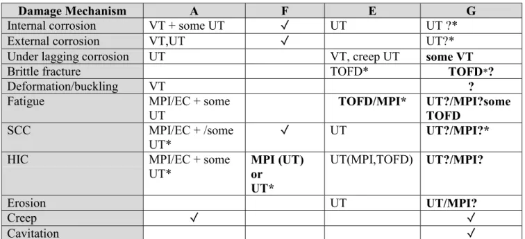
5.1.8 Summary 5.1.8.1 Likelihood
Table 5 shows, for the 5 participants that provided detailed analysis, the damage mechanisms explicitly considered. Those marked with an asterisk indicate those mechanisms considered by participants to be active or to have a possible or higher likelihood of occurrence.
It is apparent from Table 5 that there was considerable variability in the assessment of damage mechanisms. Three mechanisms were identified by all as worthy of evaluation, namely, internal corrosion, SCC and HIC. A number of others, creep, operator error, erosion, lagging breakdown, leakage, buckling, brittle fracture and under lagging corrosion were each
identified by a number but not all of the participants. Eight mechanisms were identified by one participant only.
Some care in interpretation is clearly needed here. It is possible that participants may have pre-sifted some of the mechanisms and therefore these do not appear in the their analysis. For example, all the participants may have considered creep but since the operating temperature is clearly outside the creep range did not include it as a damage mechanism for consideration. There is some inconsistency here however, creep was considered by one participant but the same participant did not explicitly consider erosion. It cannot be determined from the reports provided whether erosion was pre-sifted and, if it was, why creep was not since it was identified as being inactive. Clearly, it would be of value to the recipient of an RBI case to know whether a mechanism had been considered, judged inactive and omitted from an assessment report, or had simply been missed by the analysis team.
Arguably, damage mechanisms such as leakage or leak before break, identified by one participant, may have been considered by other participants as a sub-set one of the other mechanisms, for example, corrosion, fatigue, SCC or HIC. Operator error might be considered by some to be outside the scope of a RBI analysis.
Six damage mechanisms, brittle fracture, fatigue, SCC, HIC, internal and external corrosion were assessed as being significant by one or more of the participants. There were, however, significant differences between participants in their assessment of these mechanisms. (Note that there were some differences in the terminology used to describe the significance of damage mechanisms, some in terms of their likelihood, e.g. unlikely, possible, probable, etc and other as based on their activity, e.g. low, medium or high.)
All of the participants had considered corrosion but only two, including the case provider, believed it was an active degradation mechanism. One participant who determined internal corrosion to be inactive specified process monitoring to ensure that non-corrosive conditions were maintained in operation. In this case, if corrosive conditions occur in practice, then additional inspection activities to monitor corrosion rate and the occurrence of SSCC, SOHIC and HIC would be specified6.
Brittle fracture was assessed as possible during a blowdown event by one participant where they considered temperatures could be as low as –62oC (the minimum design temperature of the vessel). This participant considered the bed support ring to be most susceptible to this form of damage as fatigue in this area is also likely and could lead to the development of defects which exceed the critical crack size. Two of the other participants had assessed brittle fracture but did not consider it active. The remainder had either not considered or had pre-sifted the mechanism.
Fatigue had been assessed as highly probable by one and probable by another participant, in the latter case based partly on the fact that insufficient information had been provided in the case study information on cyclic stresses to make a judgement. Three participants had not considered fatigue to be active or had pre-sifted it.
6 Note that this participant considered the vessel only, and did not consider associated piping, some of which
In the assessment of SCC further inconsistencies were highlighted. One participant had identified SCC as an active mechanism based on the fact that H2S would be present in the process stream and therefore concluded that SCC was probable. One participant requested additional information on H2S, CO2 and H2O contents of the process stream and another data on H2S content, post-weld heat treatment and the pH of the H2O (this data was not available and an assumption was made). On the basis of this additional information they concluded that SCC was unlikely, as the data that was available gave a water dew point temperature below -20°C. The case provider, concluded that the mechanism was inactive in normal operation, but could be active in exceptional circumstances.
HIC was identified as being active by one participant and as possible by another. The third, based on additional information on the process stream, concluded that HIC was unlikely. The remainder, including the case provider, considered the mechanism inactive.
Of the six active mechanisms identified by the group no mechanism was thought to be active by more than three participants. Clearly the lack of consistency is of concern. The
effectiveness of the RBI system is largely dependent on the correct identification of
degradation modes and the results for this vessel show that a consensus on which mechanisms were likely to be active could not be found. Arguably, some of the mechanisms identified as active may not have been selected had more detailed information had been made available, but equally, a conservative approach should be adopted where uncertainty exists.
5.1.8.2 Consequences
Direct comparisons between the participants consequence assessments was difficult to make. In two cases software was used and the consequence was calculated via a series of variables and it was not immediately apparent how the consequence was arrived at. In one case a numerical value for business, safety and environmental considerations was derived and in the other calculated values were converted into a monetary evaluation. One participant produced a consequence rating based on a qualitative written assessment which has the benefit of transparency.
The consequence data showed a good deal of scatter, see Table 6. The full spectrum of consequences between high and low were obtained for the production/business and safety factors. In one case business and safety were assessed as high and low respectively and in another low and high. Environmental consequences were assessed by one participant as being high and low by another. The overall consequence was consistently assessed as high or medium high by all participants. The overall consequence factor was defined as the highest of the individual consequences in four cases and by the total cost in one.
5.1.8.3 Risk
Table 7 shows the likelihood and consequence data together with the risk assessments for this vessel. In four cases the risk was assessed as high or extreme and in the fifth, medium/high. The differences in the risk assessment were due to the somewhat different assessments of the likelihood of failure. This in turn was associated with the differences in the evaluations of the active damage mechanisms giving rise to the range in likelihood factors.
Given the lack of consistency in the assessment of the active damage mechanisms the assessment of risk produced a broad, possibly fortuitous, consensus.
5.1.8.4 Inspection Plan and Period
The inspection plans and the periodicity of inspection, Table 7, suggested by the participants necessarily reflected their assessment of the active damage mechanisms. The inspection periodicity was related to the damage mechanism and its rate of propagation. For those participants (A, F) that identified HIC as an active mechanism, MPI or eddy current of all highly stressed regions and 25% inspection of all welds together with ultrasonic inspection of nozzle shell junctions was proposed by one (participant A) and 100% MPI together with UT of indications was proposed by the other (participant F). In one case (participant F) HIC was the only mechanism identified as active and no other inspection recommendations were made. In participant A’s case, 3 active mechanisms were identified and inspection recommendations were made. Recommendations were also made for a number of mechanisms considered to be inactive or highly unlikely.
On the basis of these analyses participant A recommended an inspection interval of 2 years. This was based on the SAFed guidance (2) and the assumption that the vessel was Class A, i.e. subject to deterioration. A two year inspection period, IP12 (6), was also suggested by participant C and, again, extensive MPI or eddy current techniques were proposed. Participant F recommended a 3 year inspection interval based on a future inspection date of 2010 and modified by threshold values on the damage factor and total cost.
In the case of participant E, fatigue and brittle fracture were identified as having a possible or probable likelihood of occurrence. In both cases an immediate inspection was recommended using TOFD. It was also proposed that a fatigue assessment be carried out. Maximum
inspection intervals of 6 years were set for each of the other damage mechanisms assessed. In the case of HIC and SCC, process monitoring of the gas water content was recommended but there were no proposals for NDT.
Participant D did not submit an inspection plan but, on the basis of previous inspections, suggested that the vessel could be operated until the next shutdown period. On the basis of current operating procedures this could be as much as 5 years.
Inspection intervals clearly depend on the assessment of the active degradation mechanisms and these varied from participant to participant. However, even where common degradation mechanisms had been identified there were some differences in inspection intervals if not in inspection programmes.
Participant G specified MPI of critical welds, UT of support rings and external UT for internal corrosion with an interval of 16 years with a thorough internal inspection on an opportunity basis, an external surface inspection at 8 years (windows) plus TOFD after reassessment of thermal fatigue analysis.
5.2 Case 2 Distilate Hydrotreater
The case study data for this vessel are shown in Appendix 3. This case was addressed by three participants.
5.2.1 Participant E
Participant E, who provided the case study, considered a range of degradation mechanisms summarised in Table 8. Four were regarded as having a “possible” likelihood of failure, namely, high temperature hydrogen attack, sigma phase embrittlement, erosion and creep. The remaining mechanisms were thought to be unlikely to cause failure. A quantitative evaluation of creep was performed based on the applied stresses and the operating temperature and a creep rupture life of 58 years was derived. The other mechanisms were assessed qualitatively. Consequence assessments were made for each of the damage mechanisms and these showed that creep, hydrogen and temper embrittlement could produce “catastrophic consequences” on the grounds that the potential release could be large. The other mechanisms produced
consequences described as “critical”, i.e. smaller releases of material.
A semi-quantitative evaluation was made of the consequences based on the plant area, distances to plant facilities, repair time, fluid characteristics and, impact on equipment and personnel. The results gave medium/high impact on safety, a high impact on business and a medium impact on the environment. The overall impact and risk were regarded as high. An inspection plan was recommended for each of the mechanisms and included: a) for creep: dimensional checks, MPI and replication together with dye penetrant examination of the ring groove, b) ultrasonics (velocity ratio) and replication for hot hydrogen attack, c) metallurgical testing of coupons for H2 embrittlement and temper embrittlement, d) Dye penetrant
inspection (10% coverage) of the overlay for polythionic acid attack and sigma phase
embrittlement, e) internal visual inspection for sulphidisation and, f) ultrasonics and corrosion mapping for erosion. An inspection period of 6 years was recommended.
5.2.2. Participant F
The range of damage mechanisms considered, seven in total, is shown in Table 8. The vessel had not undergone an inspection since commissioning and therefore an expert evaluation of the corrosion rate was employed. Based on the H2S composition of 0.6 mole % and a
maximum operating temperature of 470oC, a corrosion rate, using Couper – Gorman curves, of 2.54 mm per year was estimated. Corrosion under insulation was not considered likely at the operating temperature and high temperature hydrogen attack was thought not applicable at the H2 partial pressure indicated in the study data. Generic failure frequencies were used and a likelihood of failure (LoF) of 9.1E-2 was generated. At the future date of 2010 the LoF was increased to 7.9E-1. Thus a likelihood category of 4 was derived.
Consequence calculations were based on the inventory, a representative chemical (n – octane – naphtha) and an H2S content of 0.15%. The resulting calculations showed that the safety, equipment and business interruption costs would be high, medium and low respectively. The overall consequence was assessed as D (high) and thus the overall risk was considered to be medium/high.
A highly effective inspection carried out as soon as possible was recommended to assess the condition of the reactor. The condition of the austenitic overlay was considered to be
particularly important. If flaws were detected during this examination a more thorough inspection of these areas using UT scanning or profile radiography with 95% to 100% coverage was recommended. This information could then be used to provide a more reliable corrosion rate for future assessments.
5.2.3 Participant C
The damage mechanisms identified by this participant as active included SCC, H2 cracking and internal pitting corrosion. The probability of failure was assessed as medium and the consequence of failure as high. In the latter case all elements of the consequence evaluation assessed as high.
The risk was assessed as medium and since no previous inspection had been carried out an inspection grade of zero was assigned. On the basis of this a 3 year inspection period was set. An internal visual inspection was recommended with dye penetrant examination of 10% of the vessel depending on the findings of the visual examination. It was further suggested that a deferral would be appropriate if a plant shutdown was planned in the next year. If a deferral was granted, however, an immediate non-invasive inspection was recommended.
5.2.4 Summary 5.2.4.1 Likelihood
Consideration of Table 8 shows that although a wide range of potential damage mechanisms were considered by the participants there were considerable differences in the view as to which mechanisms might be active. The participants each identified between 7 and 11 damage mechanisms.
Participants F and E identified a range of mechanisms only three of which were common. This observation might highlight a limitation in software based systems where the code may have been developed within a particular industrial sector and consequently may only code for degradation mechanisms active within a narrow environment. Potential degradation
mechanisms might then be missed when the software is used within another industrial sector with a potentially different set of active damage mechanisms.
A total of 7 damage mechanisms were thought to be active by one or more of the participants: internal corrosion, H2/H2S corrosion, high temperature H2 attack, SCC, erosion, creep and sigma phase embrittlement. Only one, H2 or H2S corrosion, was thought to be active by more than one participant. Internal corrosion and fatigue were the only mechanisms explicitly reviewed by all the participants.
High temperature H2 attack was thought by one (E) to be possible, albeit inactive, participant F, however, considered that the partial pressure of H2 was too low for it to be active.
Creep and sigma phase embrittlement were identified as possibly active mechanisms by one participant but were apparently not assessed by participant F. Since creep and sigma phase embrittlement are both high temperature degradation mechanisms, it is possible that the software used by Participant F had not been optimised for high temperature plant.