Lighting Control Console
User Manual
Version 2.1.0
Copyright © 2013 Electronic Theatre Controls, Inc. All Rights reserved. Product information and specifications subject to change. Part Number:4330M1210-2.1.0 Rev A Released: 2013-12
™
ETC®, Eos™,Eos Ti™, Gio®,Ion®, Element™, Emphasis®, Expression®, Insight™, Imagine™, Focus™, Express™, Unison®, Obsession® II, ETCNet2™, EDMX™, Revolution® and Sensor+®, are either registered trademarks or trademarks of Electronic Theatre Controls, Inc. in the United States and other countries.
ETC permits the reproduction of materials in this manual only for non-commercial purposes. All other rights are reserved by ETC.
1
T a b l e o f C o n t e n t s
Introduction . . . 1
Welcome to Element . . . .2
Using this Manual. . . .2
Register Your Element . . . .3
Online Element User Forums . . . .3
Help from ETC Technical Services . . . .4
Other Reference Materials . . . .5
On Screen Prompts . . . .5
Help System . . . .5
Important Lighting Concepts . . . .5
C h a p t e r 1
Quick Start . . . 7
Getting Started . . . .8
Hardware . . . .8
Power Up the Console. . . .8
Power Down the Console . . . .8
Getting the Lights On . . . .9
Setting Levels Via Channel Faders . . . .9
Setting Levels Via the Control Keypad . . . .9
Recording a Lighting Look . . . .10
Recording a Submaster . . . .10
C h a p t e r 2
Element Overview. . . 11
Console Geography . . . .12
Control Keypad Layout . . . .13
Terminology . . . .14 Littlites® . . . 14 Cleaning Element . . . .15 Outputting DMX . . . .15 Console Capacities . . . .16 Output Parameters . . . .16 Channel Counts . . . .16
Cues and Cue List . . . .16
Record Targets . . . .16
Faders . . . .16
C h a p t e r 3
System Basics . . . 17
The Central Information Area (CIA) . . . .18
Browser . . . .18
Lock the CIA . . . .18
Command Line Prompt . . . .18
Favorite CIA Display . . . .18
Locking the Facepanel. . . .19
Using Softkeys . . . .19
Context Sensitive Softkeys . . . .19
Changing Softkey Pages . . . .19
Using the Browser . . . .19
Displays . . . .20
Virtual Keyboard . . . .20
Using Direct Selects . . . .21
Direct Selects in Flexi Mode . . . .22
Clear Functions . . . .23
Display Control and Navigation . . . .24
Opening and Closing Displays. . . .24
Selecting Displays . . . .24
Moving Displays. . . .25
Scrolling within a Display . . . .25
Expanding Displays . . . .25
Show File Indicator . . . .25
[Data] Key . . . .25
[Label] Key. . . .25
Using Flexichannel . . . .26
Using [Format] . . . .27
Zooming Displays . . . .28
C h a p t e r 4
Managing Show Files . . . 33
Create a New Show File. . . .34
Open an Existing Show File . . . .34
Selective Partial Show Opening . . . .36
Merging Show Files . . . .37
Printing a Show File . . . .38
Saving the Current Show File. . . .40
Using Quick Save. . . .40
Using Save As . . . .40
Importing Show Files . . . .40
Exporting a Show File . . . .41
Importing Custom Gobo Images . . . .41
Imported Media and Partial Show Open/Merge. . . .42
Deleting a File . . . .42
File Manager . . . .42
3
C h a p t e r 5
Setup . . . 43
Opening Setup . . . .44 Show . . . .44 Desk. . . .47C h a p t e r 6
Patch. . . 51
About Patch . . . .52 Displays . . . .53Patching Conventional Fixtures . . . .54
Patching By Channel . . . .54
Range Patching . . . .54
Labeling . . . .54
[At] [Next] . . . .55
Patching By Address . . . .55
Flexichannel Views in Patch . . . .56
Using Output Address vs Port/Offset. . . .56
[Dimmer/Address] [n] [/] . . . .56
Creating multi-part and compound channels . . . .57
Replace . . . .57
Patching Scrollers . . . .58
Using the Scroller Editor. . . .59
Using the Picker. . . .59
Using the Editor . . . .60
Calibrating a Scroller . . . .64
Patching Moving Lights, LEDs, and Accessories . . . .65
Using {Offset} in Patch. . . .66
Display Pages in Patch . . . .67
{Patch} Display and Settings . . . .67
Attributes . . . .68
Database . . . .70
Using Device List . . . .71
Dimmer List for CEM+, CEM3, FDX 2000, and FDX 3000 . . . .71
RDM Device List . . . .73
Patching Discovered Dimmers and RDM Devices . . . .75
Errors and Warnings . . . .75
Detaching Devices. . . .76
Dimmer Doubling . . . .77
Moving and Copying Channels . . . .77
Swapping Channels . . . .78
Unpatch a Channel. . . .78
Deleting Channels . . . .78
Clearing the Patch . . . .79
Update Library . . . .79
Creating a New Fixture . . . .80
Copying a Fixture. . . .84
Merging Custom Fixtures into a New Show File . . . .84
Importing a Custom Fixture . . . .84
Snap Parameters. . . .85
C h a p t e r 7
Basic Manual Control . . . 87
Using Channel Faders . . . .88
Selecting Channels . . . .89
Select Channels From the Keypad . . . .89
Offset . . . .90
Using Groups as a Channel Collector . . . .90
Deselecting Channels . . . .90
Setting Intensity . . . .91
Level Wheel . . . .92
Select Last . . . .92
- Select Manual or Select Active . . . .92
Using +% and -% . . . .92 Channel Intensity . . . .92 Remainder Dim . . . .93 Rem Dim / . . . .93 Sneak . . . .94 Channel Check. . . .95 Address at Level. . . .95 Address Check . . . .95 Flash. . . .96
Moving Light Control . . . .96
C h a p t e r 8
Storing and Using Submasters . . . 97
About Submasters . . . .98
Recording a Submaster . . . .98
Submaster Displays. . . .99
Additive, Inhibitive, or Effectsub. . . .99
Proportional vs. Intensity Master . . . .99
HTP vs. LTP . . . .100
Exclusive Submasters . . . .100
Independent. . . .100
Shield. . . .101
Submaster Background State . . . .101
Submaster {Restore} Mode . . . .101
Updating a Submaster . . . .101
Labeling a Submaster . . . .102
5
Paging Submasters . . . .102
Using Bump Button Timing With Submasters . . . .103
Controlling Subfades Manually . . . .103
Controlling Submasters from the Command Line . . . .103
Submaster List . . . .104
Editing Submasters . . . .104
C h a p t e r 9
Working with the Cue List . . . 105
Basic Cueing . . . .106
Cue Numbering . . . .106
Recording Cues in Live . . . .107
Using Record . . . .107
Using Record Only. . . .107
Selective Storing Cues using [Record] . . . .108
Using [Cue Only / Track] . . . .109
Move Fade . . . .111
Timing. . . .112
Setting Cue Level Timing. . . .112
[Time][/] . . . .113
Delay Time. . . .113
Assigning Cue Attributes . . . .113
Clearing Cue Attributes . . . .115
Flags. . . .116
Block . . . .116
Preheat . . . .117
Moves . . . .117
Using the Execute List . . . .117
Modifying Cues Live . . . .118
Using [At] [Enter] . . . .118
Using Record . . . .118
Using Record Only. . . .118
Selective Storing Cues using [Record] . . . .118
[Update] . . . .119
Recording and Editing Cues from Blind . . . .122
From the Cue Spreadsheet . . . .123
Deleting Cues. . . .125
In Track Mode . . . .125
In Cue Only Mode . . . .125
Using the Cue List Index . . . .126
Open the Cue List Index . . . .126
Cue Attributes . . . .126
Auto-Block Cleanup . . . .127
C h a p t e r 1 0
Using Groups and Intensity Palettes. . . 129
Recording Groups Live. . . .130
Offset . . . .131
Subgroups . . . .131
Editing and Updating Groups in Live . . . .131
Selecting Groups . . . .132
Deleting Groups. . . .132
Group List. . . .133
Open the Group List . . . .133
Ordered View and Numeric View. . . .133
Editing Groups from the Group List . . . .133
Recording Intensity Palettes Live . . . .134
Using Intensity Palettes . . . .135
Applying Palettes . . . .135 Recalling Palettes . . . .135
C h a p t e r 1 1
Cue Playback . . . 137
Introduction to Playback . . . .138 Playback Controls . . . .138 Selected Cue . . . .139 Live / Blind . . . .139 Out-of-Sequence Cues. . . .140 Go To Cue . . . .140Loading a Cue with Temporary Timing . . . .141
Playback Fader Controls . . . .142
Go and Stop/Back . . . .142
[Go To Cue] [0] . . . .142
[Go To Cue] [Out] . . . .142
Manual Master Option . . . .144
C h a p t e r 1 2
Using Moving Lights and Palettes. . . 145
Moving Light Control . . . .146
ML Control . . . .146
Using the Color Picker . . . .147
Adjusting Parameters Using + and - . . . .148
Lamp Controls . . . .148 AutoMark . . . .149 About Palettes . . . .150 Palette Types . . . .150 Intensity Palettes . . . .150 Focus Palettes . . . .150 Color Palettes . . . .150 Beam Palettes . . . .150
Storing Palettes Live . . . .151
7
Storing Palettes with Record Only . . . .152
Using Palettes . . . .153
Applying Palettes . . . .153
Recalling Palettes . . . .154
Editing Palettes Live. . . .155
Rerecord . . . .155
Update . . . .155
Editing Palettes in Blind . . . .156
Editing in Blind . . . .156
Editing Palettes in Spreadsheet View . . . .157
Deleting Palettes . . . .157
C h a p t e r 1 3
Creating and Using Effects . . . 159
About Effects . . . .160
The Effect List . . . .161
Effects Editor . . . .162
Beats Per Minute . . . .164
Effect Status Display . . . .166
Step Effects . . . .167
Program a Step Effect . . . .168
Absolute Effects . . . .169
Program an Absolute Effect. . . .170
Multiple Intensity HTP Effects . . . .171
Relative Effects . . . .171
Focus Effects . . . .171
Color Effects . . . .172
Linear Effects. . . .172
Define a Pattern Shape . . . .173
Program a New Relative Effect . . . .173
Apply an Existing Effect . . . .174
Recording an Effect in a Cue. . . .174
Editing Effects Live . . . .174
Stop an Effect . . . .174
Deleting an Effect . . . .174
Effects on Submasters . . . .175
Recording an Effect to a Submaster . . . .175
Running an Effect from a Submaster. . . .175
Delaying Effects in Cues and Submasters . . . .176
C h a p t e r 1 4
Using About . . . 177
About [About] . . . .178 [About] . . . .179 About System . . . .179 About Channel . . . .181 About Address . . . .183 About Cue . . . .186About IFCB Palettes . . . .186
About Groups. . . .186
About Curves . . . .186
About Effects . . . .186
C h a p t e r 1 5
Advanced Manual Control. . . 187
Using [Copy To] . . . .188
Using [Recall From] . . . .189
Using Move To . . . .190
Using {Make Absolute} . . . .190
Using [Undo]. . . .191
C h a p t e r 1 6
Using Park . . . 193
Using Park . . . .194
Park Display. . . .194
Parked Values in Live . . . .194
Scaled Parked Values in Live . . . .195
Parked Addresses in Live . . . .195
Park Values from the Park Display . . . .196
C h a p t e r 1 7
Multipart Cues. . . 197
About Multipart Cues . . . .198
Record a Multipart Cue in Live . . . .198
Creating a New Multipart Cue in Live . . . .198
Setting Multipart Cue Attributes . . . .199
Using Update in Live . . . .199
Storing a Multipart Cue in Blind . . . .200
Changing a Single Part Cue to a Multipart Cue. . . .200
Creating Multiple Cue Parts in a Range . . . .200
Changing a Multipart Cue to a Standard Cue . . . .200
Deleting a Part from a Multipart Cue . . . .200
C h a p t e r 1 8
Storing and Using Curves. . . 201
About Curves . . . .202
Creating and Editing Curves . . . .203
Creating a Curve . . . .203 Editing Curves . . . .204 Applying a Curve . . . .205 To Channels In Patch . . . .205 To Cues . . . .205 To Scroller Fans . . . .205
9
C h a p t e r 1 9
Storing and Using Macros. . . 207
About Macros . . . .208
Store a Macro from Live . . . .208
Using the [Learn] key. . . .208
Macro Editor Display . . . .210
Macro Modes . . . .211
Create a New Macro in the Macro Editor Display . . . .212
Edit an Existing Macro . . . .213
Recall a Macro . . . .214
Stop a Macro . . . .214
Delete a Macro . . . .214
C h a p t e r 2 0
Using Magic Sheets . . . 215
About Magic Sheets . . . .216
Magic Sheet Display. . . .217
Magic Sheet List . . . .218
Display Tools . . . .218
Navigating a Magic Sheet . . . .219
Creating and Editing Magic Sheets . . . .221
Quick Save . . . .221
Layout Tools . . . .222
Magic Sheet Object Library . . . .224
MS Object Properties. . . .229
Address Object Color. . . .231
Editing Objects on the Magic Sheet. . . .231
Examples of Magic Sheets. . . .232
A p p e n d i x A
Important Concepts . . . 235
Important Concepts . . . .235 Channel . . . .235 Address . . . .235 Record Target . . . .235 Cue . . . .235Move Instruction and Track . . . .235
Manual Data . . . .235
Tracking vs. Cue Only . . . .236
Move Fade. . . .236
HTP vs. LTP . . . .236
Syntax Structure . . . .237
Parameters and Parameter Categories . . . .238
A p p e n d i x B
Element Configuration Utility. . . 239
Overview . . . 239
What the Utility Does . . . 239
Element Configuration Utility Reference . . . 240
General Settings. . . 241
Network Settings . . . 245
Maintenance and Diagnostics . . . 251
Local I/O . . . 255
RFR . . . 256
A p p e n d i x C
Display Conventions . . . 257
Indicators in the Live/Blind Display . . . .257
Indicators in the Playback Status Display . . . .261
Indicators in the Fader Status Display . . . .262
A p p e n d i x D
Facepanel Shortcuts. . . 263
Overview . . . 263
Facepanel and Displays . . . 263
Operations . . . 263
A p p e n d i x E
Mirror Mode. . . 265
Displays . . . 265 Configuring a Client PC . . . 265A p p e n d i x F
Remote Control. . . 269
Remotes Overview . . . .269 Phone Remote. . . .269Remote Focus Remote (RFR) . . . .270
iRFR. . . .280
Introduction 1
Introduction
Welcome to the Element User Manual. This guide is a basic resource for users of the Element control system. Additional resources available to you are listed in this introduction.
This chapter contains the following sections:
• Welcome to Element . . . .2
• Using this Manual . . . .2
• Register Your Element . . . .3
• Online Element User Forums . . . .3
• Help from ETC Technical Services. . . .4
• Other Reference Materials . . . .5
N o t e :
For information on using show control with your system, see the Eos Family Show Control User Guide, which is available for download at www.etcconnect.com.Welcome to Element
Thank you for purchasing your Element from ETC! This introduction to Element will list all the various helpful tools available to you. In addition to this User Manual, Element also has video tutorials, an online user forum dedicated completely to Element, and support from ETC Technical Services. When using Element, you are never alone. Please take a moment to learn more about the tools available to you.
Using this Manual
In order to be specific about where features and commands are found, the following naming and text conventions will be used:
• Facepanel buttons are indicated in bold [brackets]. For example, [Live] or [Enter]. Optional keys are indicated in <angle brackets>, for example, <Cue> or <Sub>.
• Browser menus, menu items, and commands you must perform are indicated in bold text. For example: In the File menu, click Open. Or: Press [Record] [Enter].
• Alphanumeric keyboard buttons are indicated in all CAPS. For example, TAB or CTRL. • Keys which are intended to be pressed or held simultaneously are indicated with the “and”
symbol. For example, [Shift] & [+].
• Softkeys and clickable buttons in the Central Information Area (CIA) are indicated in bold
{braces}. A note about <More SK> (more softkeys): this command is always indicated as optional, and is only indicated once in an instruction regardless of how many pages of softkeys exist. This is because there is no way to predict what softkey page you are on at any given time. Press <More Softkeys> until you find the required command.
• References to other parts of the manual are indicated in italics. When viewing this manual electronically, click on the reference to jump to that section of the manual.
Please email comments about this manual to: [email protected]
N o t e :
Notes are helpful hints and information that is supplemental to the main text.C A U T I O N :
A Caution statement indicates situations where there may be undefined or unwanted consequences of an action, potential for data loss or an equipment problem.W A R N I N G :
A Warning statement indicates situations where damage may occur, people may be harmed, or there are serious or dangerous consequences of an action.Introduction 3
Register Your Element
Registering your Element system with ETC ensures that you will be notified of software and library updates, as well as any product advisories.
To register your console, you will need to enroll in “My ETC,” a personalized ETC Web site that provides a more direct path of communication between you and ETC.
Register now at http://www.etcconnect.com/product.registration.aspx.
Online Element User Forums
You are encouraged to visit and participate in the ETC Element User Forum, accessible from the ETC web site (www.etcconnect.com). This gives you access to an online community of Element users where you can read about other users’ experiences, suggestions, and questions regarding the product as well as submit your own.
To register for the ETC Element User Forum:
Step 1: Go to ETC’s community web site (www.etcconnect.com/community). An introduction page to the online community will open.
Step 2: You may register for the forum using the “register” link in the introduction or by clicking the “join” link in the upper right corner of the page.
Help from ETC Technical Services
If you are having difficulties, your most convenient resources are the references given in this user manual. To search more widely, try the ETC Web site at www.etcconnect.com. If none of these resources is sufficient, contact ETC Technical Services directly at one of the offices identified below. Emergency service is available from all ETC offices outside of normal business hours.
When calling for assistance, please have the following information handy: • Console model and serial number (located on right side panel) • Dimmer manufacturer and installation type
• Other components in your system (Unison®, other control devices, etc.)
Americas
United Kingdom
Electronic Theatre Controls Inc. Electronic Theatre Controls Ltd. Technical Services Department Technical Services Department 3031 Pleasant View Road 26-28 Victoria Industrial Estate Middleton, WI 53562 Victoria Road,
800-775-4382 (USA, toll-free) London W3 6UU England
+1-608 831-4116 +44 (0)20 8896 1000
[email protected] [email protected]
Asia
Germany
Electronic Theatre Controls Asia, Ltd. Electronic Theatre Controls GmbH Technical Services Department Technical Services Department
Room 1801, 18/F Ohmstrasse 3
Tower 1, Phase 1 Enterprise Square 83607 Holzkirchen, Germany 9 Sheung Yuet Road +49 (80 24) 47 00-0
Kowloon Bay, Kowloon, Hong Kong [email protected] +852 2799 1220
Introduction 5
Other Reference Materials
On Screen Prompts
Element provides on screen prompts located above the command line to aid with programming. These context-sensitive prompts will give instructions and options based on the current display and key hits.
Help System
A help system is also contained within Element. To access help, press and hold [Help] and press any key to see:
• the name of the key
• a description of what the key enables you to do • syntax examples for using the key (if applicable)
Important Lighting Concepts
In addition to Element’s video tutorials, ETC also has a video explaining the important lighting concepts of tracking and preset. If you are new to lighting consoles, it is highly recommended that you take a few moments and view the Bobblehead Fred video, Why Did My Console Do That, http:/ /youtu.be/apOIpRtzKg0.
Additional lighting concepts are also explained in this User Manual, please see Important Concepts, page 235 to learn more.
Periodic Table of Element
The Periodic Table of Element is a handy reference guide for the various concepts and components of Element. Please visit the Periodic Table of Element, http://www.etcconnect.com/minisite/ Element/index.html.
N o t e :
Help is included on most tangible action buttons on your Element console. This includes most softkeys and clickable buttons as well as the traditional keys on the keypad.As with hard keys, the “press and hold [Help]” action can be also used with softkeys and clickable buttons.
1
Quick Start 7C h a p t e r 1
Quick Start
This chapter will walk you through the steps of quickly getting started with Element. This chapter contains the following sections:
• Getting Started. . . .8
• Hardware . . . .8
• Getting the Lights On . . . .9
Getting Started
This chapter will quickly get you started with using Element. Later chapters will go into further detail of topics touched upon here.
Hardware
Power Up the Console
Step 1: Attach the appropriate power cable to the IEC connector on the rear of the console. For a diagram of the rear of the console, See “Console Geography” on page 12.
Step 2: Press the power switch (I is “on”) under the IEC connector on the rear panel to turn power on. This will provide power to all internal electronics.
Step 3: Press the power button, located in the top left corner of the console, above the USB port. The button LED will illuminate blue to indicate the console is running. The console will boot up into the Element environment. Element is now ready for use.
Power Down the Console
Step 1: In the browser menu select Power Off Device. To bring up the browser menu, press
[Displays] twice. A dialogue box opens asking you to confirm.
Step 2: Confirm this command by pressing [Select] or clicking with a mouse the {OK} button in the dialog box. The console will power down.
-Or-Step 1: Press the power button, located on the face panel. A dialogue box opens asking you to confirm.
Step 2: Confirm this command by pressing {OK} in the dialog box or by pressing the power button again. The console will power down.
N o t e :
For additional information on setting up Element’s hardware, please see the Element Setup Guide.N o t e :
Element will display an improper shutdown message on the next power up if the Power button Level wheel Control keypad Blackout and Grandmaster Faders and bump buttons Fader Position Switch1
Quick Start 9Getting the Lights On
When Element first boots up, it will default to a 1-to-1 patch. See About Patch, page 52 for more information. Since Element starts off patched, you can begin bringing up levels immediately.
Setting Levels Via Channel Faders
For more in depth information on using Element’s channel faders, see Using Channel Faders, page 88.
Step 1: Check to make sure the Fader Position Switch is set to Channel 1-40. The first two rows of faders will then control channels 1-40. 1-20 will be controlled by the first bank and 21-40 by the second bank.
Step 2: Make sure Element is displaying in Live. Press [Live].
Step 3: Check to make sure the Grandmaster is at 100%. The top of Element’s display will show Grandmaster #% in red if the Grandmaster is below 100%.
Step 4: Check to make sure the Blackout key is not lit. It is located directly above the Grandmaster.
Step 5: You can now raise one or more channel faders to control channels 1-40.
Step 6: Lower the faders as needed to fade out channel levels.
Setting Levels Via the Control Keypad
For more information about the control keypad, see Selecting Channels, page 89. Step 1: Make sure Element is displaying in Live. Press [Live].
Step 2: Check to make sure the Grandmaster is at 100%. The top of Element’s display will show Grandmaster #% in red if the Grandmaster is below 100%.
Step 3: Check to make sure the Blackout key is not lit. It is located directly above the Grandmaster.
Step 4: You can now set levels from the keypad. Here are some examples of the syntax needed:
• [5] [Full] [Enter] - sets channel 5 to 100% or Full.
• [1] [Thru] [1] [0] [At] [7] [5] [Enter] - selects a range of channels 1 through 10 and sets their level to 75%.
• [2] [+] [7] [At] [2] <0> [Enter] - selects channels 2 and 7 and sets their levels at 20%.
• [5] [0] [Thru] [7] [0] [-] [6] [0] [At] [5] <0> [Enter] - selects channels 50 through 70, except 60, and sets their levels to 50%.
N o t e :
Use the Fader Position Switch to change the channels the faders will control. The first 120 channels can be controlled via the faders. Channel 121 and above must be controlled from the keypad.N o t e :
[Enter] must be used at the end of the command to terminate the command line. Levels will not be set until the command line has been terminated.Step 5: To remove a channel’s level, you can either use the command [At] [Enter], or you can use [Sneak] [Enter]. If you have not recorded any lighting looks yet, [At] [Enter] removes the manual value and sets to out. This will provide a manual 0 for the channel. If you store from this state, you will be storing a move to zero in the cue or submaster you stored. [Sneak] [Enter] removes the manual level and sets to the background state. If there is no cue or submaster in the background, the level will be set to its home value, resulting in a null state.
• [1] [0] [At] [Enter] - sets the level of channel 10 to 0%. • [Sneak] [Enter] - fades out all manual levels.
• [5] [Sneak] [Enter] - fades out the manual level for channel 5.
• [1] [Thru] [1] [0] [At] [Enter] - sets the levels for channels 1 through 10 to 0%. • [2] [0] [Thru] [2] [5] [Sneak] [Enter] - fades out the levels for channels 20 through
25.
Recording a Lighting Look
Submasters and cues are two ways that you can record looks to be able to recall them. This quick start will only cover recording submasters.
Recording a Submaster
For more information about submasters, see Storing and Using Submasters, page 97.
Step 1: Set the channel levels that you want in your look using the channel faders and/or keypad.
Step 2: Switch the Fader Position Switch to Submaster mode.
Step 3: Press [Record] then the bump button of the submaster you wish to record. This action will terminate the command line so there is no need to hit [Enter]. You can also record a submaster using the following syntax, [Record] [Sub] [#] [Enter], in case you don’t want to jump to submaster mode on the faders.
Step 4: You can either leave that look up and build upon it or use [Sneak] [Enter] to fade out the manual levels.
If you would like to record looks to be able to play them back using Element’s [Go] button, please see Basic Cueing, page 106.
N o t e :
If you have an Element 60 console, the third bank of faders are always in submaster mode.2
Element Overview 11C h a p t e r 2
Element Overview
Inside this chapter you will find a general overview of your Element. This chapter contains the following sections:
• Console Geography. . . .12 • Control Keypad Layout. . . .13 • Terminology. . . .14 • Cleaning Element. . . .15 • Outputting DMX . . . .15 • Console Capacities . . . .16
Console Geography
Below is a diagram of Element with references made to specific areas of use. The terms and names for each area and interface are used throughout this manual.
N o t e :
Element can support up to 2 monitors, either 2 DVI monitors or 1 VGA and 1 DVI. For monitor configuration, please See “External Monitor Arrangement” on page 243. Power button USB port Level wheel Control keypad Playback controls Blackout and Grandmaster Faders and bump buttons Fader Position SwitchVGA port DVIvideo ports
IEC receptacle MIDI Out and In
Hard power switch Ethernet
port DMX ports 1 and 2 USB ports Remote trigger port Phone remote port
2
Element Overview 13Control Keypad Layout
The control keypad area is divided into several sections including record targets, numeric keypad with modifiers, display, softkeys, navigation, and special function controls.
Display and navigation keys are used for quick access to common displays, format, paging, and navigation within displays.
The load button is located above the fader pair and is used to load the specified cue.
ll Shift Display Softkeys Navigation Special function controls Record targets and related commands
Numeric Keypad and modifiers
Terminology
Power Button
The power button on the front of the desk is used to power up or power down. A separate power switch, located in the rear panel, can be used to disconnect power from the desk’s internal components.
USB Ports
One USB port is provided on the front of the console to connect any USB storage device. Additional USB ports on the rear panel of the console can be used to connect peripherals such as an alphanumeric keyboard, pointing device, or touchscreen control for external monitors.
Level Wheel
Adjusts intensity for selected channels. It also provides scrolling and zoom functions in various modes.
IEEE Ethernet 802.3 Ethernet Port
Ethernet port for connection to a network switch, network gateways, and accessory devices.
Littlites
®
You may connect a Littlite to the side of your Element.
Dimming Littlites
Attached desk lamps can be dimmed either with the desk lamp control knob on the side of the console, or from the software.
Desk lamp controls are found in Setup >Desk >Brightness Settings. The {Desk Lamp} slider has a range of 0% (dimmest) to 100% (brightest). The default setting is 0%. The console will set the desk lamp to this setting on startup of the application. See “{Brightness Settings}” on page 49.
The desk lamps can also be controlled by holding down [Displays] and rolling the level wheel.
W A R N I N G :
Before servicing Element, you must switch off the power on the rear panel and disconnect the power cord completely.C A U T I O N :
The USB ports cannot be used for charging devices like cell phones.Littlite XLR 3-Pin Female Connector
1 2
2
Element Overview 15Cleaning Element
Should the exterior of your Element require cleaning, you may gently wipe it with a dampened (not dripping), non-abrasive paper towel or soft cloth.
If this does not clean the console sufficiently, you may apply some window cleaner (containing ammonia is fine) to the cloth and repeat the process until clean.
Outputting DMX
In order to output levels from Element, you can either use the DMX ports on the back of the console, or to output over a network, you may connect a Net3 gateway or Net2 node. If your devices receive Net3 or ETCNet2 directly, no gateway or node is required.
Element has two DMX ports. To output, connect one 5 pin XLR cable per port. The first port will default to outputting the first universe of DMX, addresses 1-512, and the second port to the second universe, outputting addresses 513-1024. See Local DMX Outputs, page 255 for information on reconfiguring the DMX ports.
Nodes and gateways will function with Element out of the box without previous configuration. However if custom configuration is required, you will need to use either NCE (Network Configuration Editor) or GCE (Gateway Configuration Editor). GCE is installed on Element by default and can be accessed in ECU>Settings>Maintenance>Gateway Configuration Editor (GCE). NCE can be installed on the console or a Windows® PC for configuration.
For more information on Net3 gateways or Net2 nodes, see the product literature that accompanied the hardware or download it from our website at www.etcconnect.com.
Console Capacities
Output Parameters
• 1,024 Outputs (DMX channels)
Channel Counts
• 250 or 500 Channels (any number from 1 to 99,999)
Cues and Cue List
• Up to 10,000 cues • 1 Active Playback • 1 Cue List
Record Targets
• 1,000 Groups• 1,000 x 4 Palettes (Intensity, Focus, Color and Beam) • 1,000 Curves
• 1,000 Effects • 1,000 Macros
Faders
• 1 Grandmaster with Blackout
• 1 Master Playback, with Go and Stop/Back • 40 or 60 Faders with bump buttons
• a maximum of 300 configurable submasters • 120 channel faders
3
System Basics 17C h a p t e r 3
System Basics
This chapter will discuss using the basic Element displays. For more display information, see
Display Conventions, page 257.
This chapter contains the following sections:
• The Central Information Area (CIA) . . . .18 • Using Softkeys. . . .19 • Using the Browser. . . .19 • Display Control and Navigation . . . .24 • Using [Format]. . . .27
The Central Information Area (CIA)
The Central Information Area (CIA) is displayed on the lower portion of the screen.
Browser
The browser is the interface for numerous functions including saving a show, opening a show, changing settings, viewing record target lists, opening displays and many other functions. Press
[Displays] twice to display the browser.
Collapse/Expand the CIA
It is possible to collapse the CIA from view. You can collapse the CIA by pressing [Displays] or by clicking the double arrow icon on the right side above the CIA. The CIA will collapse from view, exposing a larger viewing area of whatever display is visible above the CIA.
To expand the CIA into view again, press [Displays] or click the double arrow at the bottom of the screen. The CIA will reopen.
Lock the CIA
You can lock the CIA in place to prevent it from being collapsed.
To lock the CIA, click on the lock icon above the browser. The double arrow above the CIA will disappear and the lock will “lock” the CIA to hold it in place.
To unlock the CIA, click the lock again and the double arrows will reappear.
Command Line Prompt
Directly above the command line, you will see red text that will prompt you for an action. The prompts will change between different displays and actions, and are useful information to aid you in programming.
Favorite CIA Display
You can select a favorite default display for the CIA that will show when [Displays] is pressed. The standard default display for the CIA is the Browser.
The favorite display will show a gold star icon at the top of the CIA by the double arrows & lock.
Browser Double arrows
CIA show/hide CIA lock (shown unlocked) Command Line
Prompt
Softkeys
3
System Basics 19the CIA. Click on the grey star to make that display your favorite. That display will now be the new default display for the CIA. Displays that show up in the CIA but can not be the default display will not show the star icon.
The following displays can be set as the favorite CIA default: • About • Browser (default) • Color Picker • Virtual Keypad • ML Controls • Effects Status • Direct Selects
Locking the Facepanel
It is possible to lock out the facepanel, which prevents any actions from the command line or CIA. To lock out the facepanel, press [Shift] & [Escape]. To unlock the facepanel, press [Shift] & [Escape] again.
Using Softkeys
Some of the features and displays in Element are accessible from the softkeys, which are located in the bottom right area of the CIA. Those softkeys correspond to buttons [S1] - [S6] and [More SK].
Pressing the [Displays] button accesses the following softkeys: • Effect Status • Color Picker • Patch • Setup • Browser • Magic Sheet • Command History • Curves • Show Control
Context Sensitive Softkeys
Softkeys are context sensitive and will change depending on the active display, the current command line, the active record target, and so on.
Changing Softkey Pages
When there are more relative softkeys than the six available buttons, the LED in the [More SK]
button will light. Press [More SK] to view the additional softkeys.
Using the Browser
To use the browser, you must first draw focus to it by pressing the [Displays] key. If the browser is not visible, double pressing [Displays] will always bring up the browser.
When focus is on the browser, the window border highlights in gold. The scroll lock LED illuminates red and the paging keys will now control selection in the browser.
• Use the page arrow keys to move the selection bar up and down the list. You can also use the level wheel to scroll through the list.
• When the bar highlights the desired menu, press [Page
] to open the menu. • Continue pressing [Page
] to open submenus.• Scroll to the item you wish to open using [Page
] or [Page
] and then press [Select]. You may also click the item you wish to open and then press [Select]. You can also use the level wheel to scroll in the browser.• If you wish to close a submenu scroll to that item and press [Page
]. • To draw focus to the browser at any time, press the [Displays] key. • Additional presses of [Displays] will minimize or restore the CIA.Displays
Several displays can be opened right from the browser. Each display will open as a new tab, except for Mirror Mode, which will open in the CIA. The following displays are available under
Browser>Displays:
• Split Channel View See page 31
• Magic Sheet Display See page 217
• Patch See page 53
• Park Display See page 194
• Show Control Display See page 45
• Mirror Mode See page 265
Virtual Keyboard
It is possible to open a virtual keyboard in the CIA which mimics the hard keys found on the actual Element keypad. This virtual keyboard is accessible from the browser.
Menu arrows
Opened menu
Sub menus Scroll bar Selection bar
3
System Basics 21To open the Virtual Keyboard on a monitor:
Step 1: Go to Browser>Virtual Controls>Virtual Keyboard. A window will open in the CIA displaying your monitor placement options for the keyboard.
Step 2: Click the placement option in which you want the keyboard to appear.
Using Direct Selects
Direct selects allow access to a number of controls. If there are more items than can be viewed at once, you may view subsequent pages by using the page buttons ({Page
}, {Page
}) by the direct selects.Opening Direct Selects
Element gives you the option of opening direct select modules on the monitors. There are two options for opening the direct select modules, which are Fit to Screen and Classic Layout. Fit to Screen is designed for wide format displays, and Classic Layout is a fixed layout, which will always display 20 direct selects across the screen.
To open the direct selects on a monitor:
Step 1: Go to Browser>Virtual Controls> Direct Select Module (Fit to Screen) or Direct Select Module (Classic Layout). A window will open in the CIA displaying your monitor placement options for the module.
Step 2: Click the placement option in which you want the module to appear.
To close the direct selects on a monitor:
Step 1: Go to Browser>Virtual Controls>Close Module. The placement screen will appear again in the CIA.
Step 2: Click the placement of the module you wish to close. The module will be removed. For information on populating direct selects see Organizing the Direct Selects.
Organizing the Direct Selects
You have considerable flexibility in how you organize the direct selects. They may be arranged to display one of several different types of data.
To choose which information to view:
Step 1: Click the {Select} button for any block of direct selects. You will be offered the following choices to view: Channels, Groups, Intensity Palettes, Focus Palettes, Color Palettes, Beam Palettes, Macros, Effects, and Magic Sheets.
Step 2: Click the button for the data you wish to view and the associated direct selects will populate with any recorded information of that type. If there is no recorded information of that type the block of buttons will remain empty but will populate with data of that type as associated record targets are stored.
Step 3: You may also click {Select} again, without choosing any option, to return to the previous state.
You can increase/decrease the size of any set of direct selects by pressing the {20/50} or {40/100}
button.
You may also press the {Expand} button (located beneath the {Select} button) to expand a set of direct selects to full screen. Press {Expand} again to return the set to its previous size and mapping. Century and Millennium buttons will display when direct selects are in expand mode. When the direct selects are opened on a tab, two sets of direct selects will be displayed.
Selecting Channels with Direct Selects
Channel direct selects are highlighted when selected. Channel selection is generally an additive process, if channels 1-5 are selected, pressing {Channel 6} adds channel 6 to the selection, leaving channels 1-5 also selected. Pressing {Channel 6} again will deselect the channel. If you have labeled channels in patch, those labels will be displayed above the channel number when viewing channels in the direct selects.
It is possible to double hit a channel button. This selects that channel and deselects any previously selected channels.
• {Channel 1} - adds channel 1 to currently selected channels, if not currently selected. • {Channel 1} {Channel 10} - adds channels 1 and 10 to currently selected channels. • {Channel 1} {Channel 1} - selects channel 1, deselects all other channels.
• {Page
} - pages direct selects down by one page. • {Page
} - pages direct selects up by one page.Selecting Other Controls with Direct Selects
Selecting other controls, such as palettes, effects, macros, and magic sheets, will terminate the command line. To post a control to the command line without terminating it, hold down [Shift] while pressing the direct select.
Direct Selects in Flexi Mode
Direct selects can be placed into a flexi mode, which will remove empty tiles. When {Select} is pressed, the {Show Flexi} button will display.
N o t e :
A single empty direct select tile may remain if the adjacent direct select tiles are not sequential. This is to allow an easy way to insert a new direct select between the existing ones.On
Off
Show Flexi is Off
3
System Basics 23Clear Functions
You can access the various clear options from the browser by selecting {Clear} from the main browser menu. The clear functions window will open in the CIA.
From this menu you can select one of the available clear options by clicking on the desired button in the CIA. Element will ask you for a confirmation before performing the selected clear. For {Clear Targets}, Element will allow you to choose which record targets you want to clear.
From the {Clear Targets} screen you can select which record targets you wish to clear. The buttons at the center of the CIA represent all of the record targets that you can choose to clear. By default all components are selected (gray) and will be cleared. To withhold any targets from being cleared, simply deselect them in the CIA by clicking the respective button.
To reselect all targets, click the {Reset} button and all buttons will return to gray (selected). To stop the process, click the {Cancel} button.
When you have selected or deselected all of the record targets you require, click {OK}.
After clearing, the CIA will return to the browser. If you want to perform additional clear functions, you must select {Clear} from the browser again.
To exit the clear functions screen without clearing, press the [Displays] key at any time or select a clear button and then select {Cancel} from the confirmation screen.
Reset System vs Clear Show
Using {Reset System} will open a new show file and reset the Setup options to their defaults. Using
{Clear Show} will only open a new show file.
Reset Patch vs Clear Patch
Using {Reset Patch} will clear your patch and set it to a 1-to-1 patch. Using {Clear Patch} will only clear out the patch.
Display Control and Navigation
Opening and Closing Displays
Tabs are shown at the bottom of the displays.The live/ blind display will always open as tab 1. The playback status display will always open as tab 2. Neither of these displays can be closed.
Other displays are numbered as they are opened. Tab numbering is useful for navigating to views. Displays can be opened and closed in different ways, depending on the display. Many displays are accessible from Element’s keypad, while other displays are accessible from the browser and softkeys. List views of record targets can be quickly accessed by double pressing the record target button, such as [Sub] [Sub] will display the submaster list.
From the hardkeys
Several displays are opened directly from buttons on Element’s keypad. Those displays are [Live],
[Blind], [Patch], [Setup], [Park], [Displays], and [ML Control]. You can open list views of any record target by double-pressing the key for the desired record target
From the browser
Open and navigate the browser as described in Using the Browser, page 19. When you open a new display (such as the group list), it will open on the primary display. If the display does not open to a monitor (such as setup or the browser) it will open in the CIA. Some displays are available from the softkeys when the [Displays] button is pressed.
Again, any time you wish to return to the browser, simply press [Displays] twice.
Closing Displays
To close any tab display, select the display by using the [Tab] key or other means of navigation. When the desired display is active, press [Escape] to close it.
To close a display in the CIA, press the [Displays] key and the browser will reappear.
To close all displays except for the live/blind display and the playback status display (tabs 1 and 2), press [Shift] & [Tab].
Selecting Displays
When a display is selected, the screen is highlighted in a gold border and the display name (such as “1. Live Channel”) will be in gold as well. When a display is not selected, there is no border and the tab name is gray.
If a display is already open, it can be selected in the following ways:
• Press [Tab] to change focus from the currently selected tab to the tab immediately to the right. If no tabs are to the right, the selection moves to the first tab on the left of all available monitors. • Press [Tab] & [n], where “n” represents the tab number of the desired tab.
• Press [Live] or [Blind] to automatically bring live/blind into focus. If you have opened the split channel display (which is also a live/blind view), pressing [Shift] + [Live] / [Blind] toggles between tab 1 (live/blind) and the split channel display. See “Split Channel Display” on page 31.
• Double press a record target button (such as [Submaster]) to either open the associated display or select it if it is already open.
3
System Basics 25Moving Displays
To move the active display from one monitor to another, press and hold the [Tab] key and use the page arrow keys to move the display in the direction of the desired screen. One press of the left or right page keys will move the display to the next screen in that direction. To move it back, press the opposite arrow key.
Scrolling within a Display
By default the page keys will advance/retreat a display by one page per press. However, to scroll through displays you may press the [Scroll Lock] key on the keypad. The LED on the button illuminates red when in scroll lock mode.
Scroll lock is a toggle state. When scroll lock is first pressed:
• [Page
] - scrolls table, spreadsheet and channel views down, • [Page
] - scrolls table, spreadsheet and channel views up, • [Page
] - scrolls table and spreadsheet views right, • [Page
] - scrolls table and spreadsheet views left.Expanding Displays
[Expand] allows a display to be viewed across multiple monitors.
To expand a display to an adjacent monitor, press [Expand] & [Page
] if in table views or[Expand] & [Page
] if in either view.To collapse an expanded view, press [Expand] & [Page
] if in table views or [Expand] & [Page
] if in summary views.Show File Indicator
When a show file has been modified but not saved yet, an asterisk (*) will display beside the show file name at the top of the displays. See
Saving the Current Show File, page 40 for more information on saving.
[Data] Key
Pressing and holding [Data] allows you to view the values behind any referenced or marked data.
[Data] exposes the next lower reference level. So if you view a palette reference and press [Data], the absolute data will be displayed instead.
You can lock this mode by pressing [Shift] & [Data]. When in display reference values mode, “Data Latched” will display in the upper left of the live display. To exit this mode, press [Shift] & [Data]
again.
[Data] can also be used to change the address views in patch. See “Using Output Address vs Port/ Offset” on page 56.
[Label] Key
[Shift] & [Label] can be used to toggle the display between showing the palette number or its label. To see the labels by default, you will need to enable Show Reference Labels in Setup. See “Show Reference Label” on page 48.
Using Flexichannel
Flexichannel (use of the [Flexi] key) allows you to view only channels meeting a certain criteria in the live/blind display, therefore removing unwanted data from view. Flexichannel has several available states which include allowing you to view:
• All channels
• All patched channels • Manual channels
• All show channels (any channels that have data stored in a cue or submaster) • Active channels (channels with intensity above zero or a move instruction) • Selected channels
• View channels
In flexi mode, any selected channels (including the last channel selection) are always included in the view. Gaps in channel numbers are indicated by a vertical line between the channels where a gap in numbering occurs.
To change flexi modes in the live/blind display, press [Flexi] to cycle through the views listed above. When [Flexi] is held down, the softkeys change to represent all of the available flexi states. You can select the desired flexi view from those keys.
[Next/Last] can be used to select the next or last channel in the current flexi mode.
[Thru] can be used to view only channels in the current flexi mode (except for selected channels mode) as long as either the first or last channel in the [Thru] range is included in the current flexi mode. To include channels not in the current flexi mode, [Thru] [Thru] can be used.
View Channels
You may select specific channels to appear in another flexichannel state called “View Channels”. This state does not exist until you select channels to view. After view channels is activated, it will appear in the rotation of flexichannel states when [Flexi] is pressed.
To select channels to view:
Step 1: Select channels on the command line (do not press [Enter]). Step 2: Press and hold [Flexi].
Step 3: Press {View Chans}. The “View Channels” flexi state will be created and the channels you selected will be visible in it.
The channels you selected will be visible in this flexi state until you select other channels and press
{View Chans} again. At any time, you can access the last channels you defined for this state by pressing [Flexi] until this state is visible.
3
System Basics 27Using [Format]
Some displays have multiple formats. When the display is first opened, it opens in its default view. The default view for Live/Blind is table view. Pressing [Format] will toggle between table, summary, and, if in Blind, spreadsheet views.
Live and Blind share formatting. When you change from one format to another format, you are always working with the same format until you change it. The exception to this is spreadsheet, which is only available in blind. If you are working in blind spreadsheet, when you return to live you will be working with the table or summary view, based on which one you were last using.
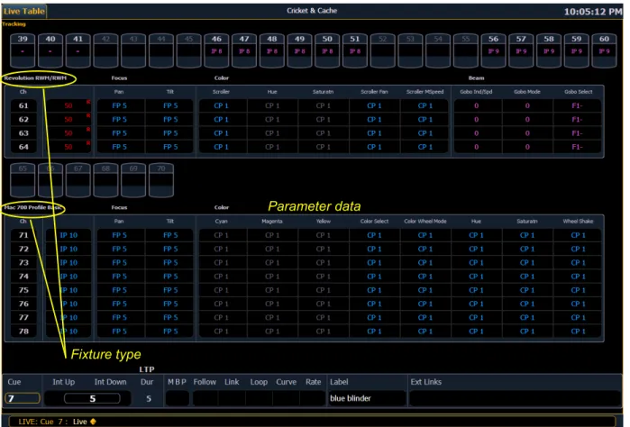
Table View
Table view is available in live or blind. If devices other than dimmers are patched, table view displays the fixture type associated with channels and details about each channel’s category and
parameter levels.
In live, table view displays all active channel data being output from Element. In blind, it will display all data for a single record target (cue, palette, submaster).
In the table view, a slight space is provided between fixture types, giving a clear delineation between them. The name of the fixture type is displayed at the top of the section for that fixture.
Fixture type
Summary View
The summary view displays the largest number of channels of any of the formats. Below you can see channels 1-80 are shown. This format is best used to see large numbers of channels’ intensity data or parameter category data. Individual non-intensity parameters are not visible in this view.
Zooming Displays
You may zoom the table and summary view to display more or less channels. To do this, press and hold the [Format] button and scroll the Level Wheel to alter the number of channels visible. Scrolling the wheel up zooms in. Scrolling the wheel down zooms out. Zooming this display when it is in 100 channel mode is not supported. A mouse can also be used to control zooming by holding down the left button while using the scroll wheel.
Channel numbers Intensity data
F, C, B data
Deleted channel
3
System Basics 29Spreadsheet (Blind Only)
Spreadsheet format is available only in blind mode. It is useful for viewing and editing channel data and trends for multiple cues, submasters, or palettes at one time. Cues and other record targets are displayed on the vertical axis and channel data is visible on the horizontal axis. See “Recording and Editing Cues from Blind” on page 122.
To toggle between viewing just the intensity information and other parameters, press [Shift] & [Format].
Channel number
Playback Status Display
The playback status display allows you to view a range of cues in the cue list and all the cue attributes for those cues.
Holding down [Time], while a cue is fading, will display the cue category times counting down in the cue list display area. The default action is to show the total time not the countdown. To always show the countdown, a {PSD Time Countdown} option is available in Setup, see {Displays}, page 48. When the {PSD Time Countdown} is enabled, the cue times will countdown as a cue is fading. In the PSD, timing will individually turn gold when that timing has completed. To see the total time, hold down the [Time] key. {PSD Time Countdown} is “disabled” by default.
An optional command line for the playback status display is available. The optional command line must be enabled to use. See {Displays}, page 48.
To hide a column in the playback status display, hold down [Escape] and click on the column you want to hide. Press [Shift] + [Select] to display all hidden columns.
For more information about the playback status display, see Indicators in the Playback Status Display, page 261.
3
System Basics 31Split Channel Display
The split channel display shows channels at the top and the playback status display at the bottom. This display is opened by going to Browser>Displays>Split Channel. It will open up as a new tab.
4
Managing Show Files 33C h a p t e r 4
Managing Show Files
This chapter explains how to create, open, and save your show files. Each of these operations are accomplished through the browser area.
This chapter contains the following sections:
• Create a New Show File. . . .34 • Open an Existing Show File . . . .34 • Merging Show Files. . . .37 • Printing a Show File. . . .38 • Saving the Current Show File. . . .40 • Using Quick Save. . . .40 • Using Save As . . . .40 • Importing Show Files. . . .40 • Exporting a Show File. . . .41 • Deleting a File. . . .42 • File Manager. . . .42
Create a New Show File
To create a new show file, navigate within the browser to: File> New> and press [Select]. You will be prompted for confirmation that you want to create a new show. Any unsaved show data will be lost. Press [Select] or click {OK} to confirm or {Cancel} to discontinue the operation. In Element, a new show file defaults to a 1-to-1 patch. Clicking {Patch 1to1} will deselect the option and result in a blank patch.
Open an Existing Show File
Names of show files may appear in the browser list in normal textor in bold text. Files in normal text indicate that there is only one show file stored by that name.
Bold show names indicate that there are several versions of the show file stored under that name, the bold one being the most recent. To access the most recent show file, simply select the bold name. You can use [Page
] from the bold name to expand a list of previous versions beneath it in the browser. Select the desired show from the expanded list.To open an existing Element show file, navigate within the browser to: File> Open> and press
[Select].
Element provides you with multiple locations to retrieve an Element show file (.esf) including: • Show File Archive - This is the default storage location for show files when a show file is
created and saved. Older versions of the show file will be listed under the most current version. This allows you the ability to open the latest version or an earlier version of a show file if desired.
• File server - if one is connected. When there is no file server connected, it will not display in the browser. See “Network Drives” on page 253.
• USB storage device - When a USB device is connected and an Element show file (.esf) is available on the device, you will notice the USB device’s name and drive letter are displayed in white text and expandable.
Open the desired location:
• To open a show file from the Show File Archive, navigate within the browser to: File> Open> Show File Archive and press [Select].
• To open a show file from the file server, navigate within the browser to: File > Open> Name of File Server> and press [Select].
• To open a show file from a USB device, navigate within the browser to: File> Open> Name of Drive and press [Select].
4
Managing Show Files 35Select the specific show file
• Navigate within the specified storage location and select the show file you wish to open, press
[Select].
• If the selected show has multiple time stamps and you wish to load an older version, navigate to the desired revision under the show file heading and press [Select].
This will open the partial show loading screen in the CIA.
From this screen you can select which components of the show file you wish to load. The buttons at the center of the CIA represent all of the show components that you can choose to load. By default all components are selected (gray) and will be loaded. To withhold any show components from loading, simply deselect them in the CIA by clicking the respective button.
To reselect all show components, click the {Reset} button and all buttons will return to gray (selected). To stop the show load process, click the {Cancel} button.
When you have selected or deselected all of the show components you require, press [Select] or click {OK}.
Element loads the selected show to the console.
N o t e :
You will need a mouse, keyboard, or touchscreen to deselect options.C A U T I O N :
On a partial show open, if any record targets are not opened, any existing data of other types will be cleared from the console.To merge show data, merge should be used. See “Merging Show Files” on page 37.N o t e :
If the loaded show file exceeds the console’s output capacity, an advisory will display in the CIA. You will need to dismiss the advisory by pressing {Ok} before continuing. To see the capacity of the console, press [About]. See [About], page 179 for more information.Selective Partial Show Opening
If you select the {Advanced} button in the partial show opening screen, you will have the
opportunity to load partial components from the show file and be able to specify the desired location of those partial components in the new show file.
For example, you could specify only cues 5-10 and load them as cues 20-25 in the new show. You could also specify only specific palettes, effects, and so on. To see the complete list of show components, press the {Advanced} key in the partial show loading screen.
As you specify components, they are added to a table in the CIA. In the table, fields with a dark background may be edited, fields with a light gray background do not apply to that component. For each component in the list, you can specify the desired range by clicking in the proper area in the table and entering numbers from the keypad. The columns in the table are:
• List - The list you are taking data from (such as a cue list). • List Target - The list you are adding the data to.
• Start - The first in a range of components (such as a range of cues). • End - The last in a range of components.
• Target - The desired location of the components in the new show file (for ranges, this will be the location in the new show of the first component in the range, the others will follow in order).
Partial Patch Opening
You have the option to selectively open partial patch information or fixtures into a show file by selecting the {Advanced} button in the partial show opening screen.
You can specify the desired range by selecting the proper area in the table and entering numbers from the keypad. The columns in the table that relate to patch are:
• Start - The first in a range of components. • End - The last in a range of components.
• Target - The desired location of the components in the new show file (for ranges, this will be the location in the new show of the first component in the range, the others will follow in order).