Journal of Electrical Engineering,
Electronics, Control and Computer Science –
JEEECCS, Volume 1, Issue 1, pages 26-32, 2015
A Didactic Implementation of a Minimalist
Compiler
Florin-Marian Bîrleanu
Dep. of Electronics, Comp. Sc.and Elect. Eng. FECC, University of Pitesti
Pitesti, Romania [email protected]
Cosmin-Ionuţ Măciucă
Kiwee Comunicatii – AGInteractive Bucharest, Romania [email protected]
Bogdan-Adrian Enache
Dep. of Electronics, Comp. Sc.and Elect. Eng. FECC, University of Pitesti
Pitesti, Romania [email protected]
Abstract – This paper presents a manual implementation using the C# language of a minimalist compiler for didactic purposes. The design and implementation steps are clearly explained in order to be easily understood. We also present a graphical user interface software application that was built for facilitating the testing of our compiler and the analysis of the intermediate results.
Keywords - formal languages; regular expressions, context-free grammars; compilers; scanning; top-down parsing
I. INTRODUCTION
Compilers are still seen in an aura of mysthicism by the majority of software programmers. It it not only their intrinsic difficulty that is responsible for that, but also the manner in which their construction is presented in the literature, where too much accent is put on the mathematical aspects while too little is said about the practical techniques for the actual design and programming of a custom compiler. We do not deny in no way the outstanding quality of textbooks such as [1], [2], [3], [4], and [5] which present very well the theory of formal languages and compiler design. We only consider necessary to approach the subject of compiler implementation from a more simplistic and didactic perspective, going thus in a similar philosophy with papers like [6], [7], and [8]. We wish to contribute thus to facilitating the subject of compiler construction for a wide range of programmers. Even if the current state of the art in programming is more and more high-level, abilities such as those involved in constructing a compiler may prove to be very useful in various practical programming situations.
Hence, we present in this paper a minimalist compiler that was realized in a didactic manner. We used for its implementation the C# language, which is a modern and very actual programming language nowadays, our purpose being (beside others) to show practical means to transpose in this language the theoretic concepts underlying the construction of a compiler. The specificatins for our compiler can be found in Section II, and the presentation of its design and implementation are in Section III. In Section IV is presented an example of use for the resulted application and the paper is closed by presenting the conclusions in Section V.
II. SPECIFICATIONS
The hardware platform targeted by our compiler is a virtual microcontroller called Octissimo (that we also built for didactic purposes). Next is presented some information about this microcontroller.
Octissimo is an 8-bit microcontroller that can perform arithmetic (addition and substraction) and logic operations (byte-wise as well as bit-wise). It contains a program memory of 64x16 bits and a data memory of 64x8 bits that it can access both directly and by the use of the stack operations. It has sixteen 8-bit general purpose registers, called R0, R1, ... R15. It also has three 16-bit special purpose registers: IR (instruction register), which is used for storing the current instruction, SR (status register), which is used for storing flags (such as: Z (zero flag), C (carry flag), O (overflow flag), N (negative flag)) about the result of the previously performed operation, and SP (Stack Pointer), which is used for addressing the next available element for storing data into the stack. The instructions supported by the Octissimo microcontroller are shown in Table I.
TABLE I. THE INSTRUCTION SET OF THE OCTISSIMO MICROCONTROLLER
Crt.
No.
Instruction code
Mnemonic Parameters Operation
15:12 11:8 7:4 3:0
1 0000 Value (12-bit) JNZ Val_12 if Z = 0 PC ← PC + Val_12
2 0001 Value (12-bit) JPZ Val_12 if Z = 1 PC ← PC + Val_12
3 0010 Value (12-bit) JNC Val_12 if C = 0 PC ←
PC+Val_12
4 0011 Value (12-bit) JPC Val_12 if C = 1 PC ←
PC+Val_12
5 0100 Value (12-bit) JNN Val_12 if N = 0 PC ←
PC+Val_12
6 0101 Value (12-bit) JPN Val_12 if N = 1 PC ←
PC+Val_12
7 0110 Value (12-bit) JNO Val_12 if O = 0 PC ←
PC+Val_12
8 0111 Value (12-bit) JPO Val_12 if O = 1 PC ←
PC+Val_12
9 1000 Value (12-bit) JMP Val_12 PC ← PC + Val_12
10 1001 i Value (8-bit) MOV Ri , Val_8 Ri ← Val_8
11 1010 i j k STR Ri , Rj, Rk ( RjRk ) ← Ri
12 1011 i Value (8-bit) STR Ri , Val_8 (Val_8 ) ← Ri
13 1100 i j k LDR Ri, Rj, Rk Ri ← ( Rj Rk )
14 1101 i Value (8-bit) LDR Ri , Val_8 Ri ← ( Val_8 )
15 1110 Value (12-bit) CALL Val_12 Call routine at Val_12
16 1111 0000 i j MOV Ri , Rj Ri ← Rj
17 1111 0001 i j ADD Ri , Rj Ri ← Ri + Rj
18 1111 0010 i Val_4 ADD Ri , Val_4 Ri ← Ri + Val_4
19 1111 0011 i j ADC Ri , Rj Ri ← Ri + Rj +
Carry
20 1111 0100 i j SUB Ri , Rj Ri ← Ri - Rj
21 1111 0101 i Val_4 SUB Ri , Val 4 Ri ← Ri – Val_4
22 1111 0110 i j SBC Ri , Rj Ri ← Ri - Rj -
Carry
23 1111 0111 i j AND Ri , Rj Ri ← Ri And Rj
24 1111 1000 i j ORR Ri , Rj Ri ← Ri Or Rj
25 1111 1001 i j XOR Ri , Rj Ri ← Ri Xor Rj
26 1111 1010 i Bit SET Ri , Bit Ri (Bit) ← 1
27 1111 1011 i Bit CLR Ri , Bit Ri (Bit) ← 0
28 1111 1100 i j CMP Ri , Rj Set flags for SUB Ri, Rj
29 1111 1101 0000 i INV Ri Ri – Negate bits
30 1111 1101 0001 i SHL Ri Ri – Left shift
31 1111 1101 0010 i SHR Ri Ri – Right shift
32 1111 1101 0011 i ROL Ri Ri – Rotate left
33 1111 1101 0100 i ROR Ri Ri – Rotate right
34 1111 1101 0101 i PSH Ri Stack push
35 1111 1101 0110 i POP Ri Stack pop
36 1111 1101 0111 − RET Return from CALL
37 1111 1101 1000 − RTI Ret. from interrupt
38 1111 1101 1001 − ENI Enable interrupts
38 1111 1101 1010 − DSI Disable interrupts
40 1111 1101 1011 − NOP Do nothing
41 1111 1101 1100 − STP Stop
42 1111 1101 1101 −
Available for extensions
43 1111 1101 1110 −
44 1111 1101 1111 −
45 1111 111- − −
TABLE II. THE TOKEN TYPES ACCEPTED BY OUR COMPILER
Token Regular expression
(1) Identifier [a-zA-Z_]([a-zA-Z_0-9])*
(2) Number 0|[1-9]([0-9])*
(3) Separator ;
(4) Equal =
(5) OpRel ==|!=|>|<|>=|<=
(6) OpArit +|-|*|/|%
(7) ParOpen (
(8) ParClose )
(9) BktOpen {
(10) BktClose }
(11) Main main
(12) Int int
(13) If if
(14) Else else
(15) While while
III. DESIGN AND IMPLEMENTATION
The compilation process is performed by a single pass through the input source code and it consists in three consecutive steps (lexical analysis, syntactic analysis, and code generation), the output of one step being the input of the next one. In the next part each of these three steps that are used by our compiler are presented.
A. Lexical Analysis
The role of the lexical analyser is to go through the source code character by character and to identify the lexemes, i.e. to split the source code into words that are understood by the compiler. It outputs a list of tokens, i.e. symbolic names for each of the types of lexemes encountered. While some lexemes are fixed-form (such as the symbol "+" used for the addition operator), others can have various forms (such as the identifiers). For the latter category it is necessary to store in the token list not only the type of the lexeme, but also its value (i.e. the actual character sequence read from the source code). Hence, for the token list output by the lexical analyzer a structure that contains two fields – type and value – was used.
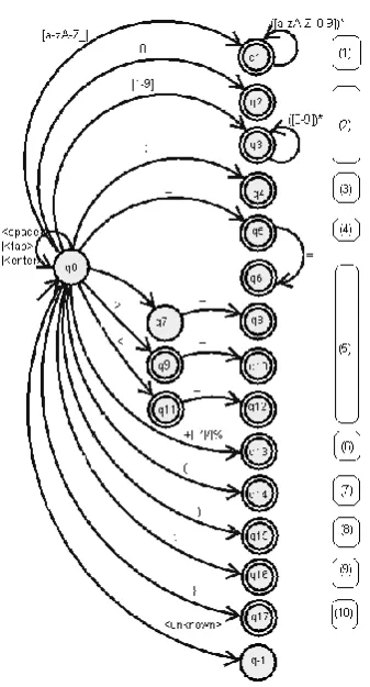
new state is also an accepting state. Otherwise we stay in the current state, we store the token found and we unread the last character read, by restarting the automaton from its start state. (The transitions that are not shown in Figure 1 move states q1, q2, ..., q17 to state q0, and state q-1 to state q-1.) Each token found is then stored in a data structure that contains, as we said before, the type and the value of the token. In order to facilitate the software simulation of the automaton, the transition diagram shown in Figure 1 was stored in our program as a transition table, i.e. a matrix having as many rows as the number of states of the automaton and as many columns as the number of symbol types that can appear in the input word. An element t[i][j] in this matrix contains the index number of the destination state for state i when the input symbol is of type number j.
Figure 1. The deterministic finite automaton used by our lexical analyzer.
B. Syntactic Analysis
The input of the syntactic analyzer is the output of the lexical analyzer, that is a list of pairs (token type, token value). While the role of the lexical analyzer is to verify that the symbols in the source code make up valid words, the role of the syntactic analyzer is to verify that the words found in the source code by the lexical analyzer make up a correct phrase.
The syntactic structures that are accepted by our compiler are specified by a context-free grammar. This grammar is shown in Table III. The variable Expression was not detailed in the table because (in over to simplify things) the expressions were treated separately. The expression parser reads the expression token by token and builds its postfix Polish form, which it then uses for building the syntax tree that
corresponds to the expression. In order not to complicate things, all the operators were considered to be left to right associative and to have the same precedence (which can be modified by the use of parentheses). We must note that treating expressions separately was not mandatory. They could be included in the grammar shown in Table III by adding some more productions (as Table IV shows).
TABLE III. THE CONTEXT-FREE GRAMMAR USED BY OUR PARSER
Program → <Main><ParOpen><ParClose> <BktOpen> Instructions <BktClose>
Instructions → Instruction Instructions | ε Instruction → Declaration | Assignment |
Decision | Repetition
Declaration → <Int><Indentifier><Separator> Assignment → <Identifier><Equal>Expression
<Separator>
Decision → <If><ParOpen>Expression <ParClose><BktOpen> Instructions<BktClose><Else> <BktOpen>Instructions <BktClose>
Repetition → <While><ParOpen>Expression <ParClose><BktOpen> Instructions<BktClose>
TABLE IV. A POSSIBLE GRAMMAR FOR HANDLING EXPRESSIONS
Expression → Operand RestExpr
RestExpr → ε | Operator Operand RestExpr Operator → <OpArit> | <OpRel>
Operand → <Identifier> | <Number> | <ParOpen> Expression <ParClose>
The task of the syntactic analyzer is to go through the list of tokens element by elements and convert it to a syntax tree according to its grammar. This can be easily done by implementing a LL(1) parser. It can be done as a backtrack-free top-down parsing algorithm that is both efficient in terms on complexity and it can be easily implemented manually (as opposed to bottom-up parsers) [4]. This parser requires that the grammar is a LL(1) grammar (i.e. a grammar that is free from left recursion and that allows the choice of a production only by reading at most one character in advance).
C. Code Generation
The last step performed by our compiler receives as input the syntax tree generated by the parser and performs its depth-first traversal, in the same time generating at each step the corresponding instructions in the machine language known by our microcontroller. No optimization is made, and the variables are stored in memory in the order in which they are declared in the program. (In order to easily manipulate variables, we use an object of type Dictionary, which allows us to rapidly search variables by their name.)
As an example, for the following code sequence (written in the language recognized by our compiler)
var a; a = 10;
the code that results after the code generation step is the following (written in assembly language, for a better lisibility):
MOV R1, hA MOV R2, b00000000 MOV R3, b00000000 STR R1, R2, R3
We made the assumption that the variable named a
is the first variable declared in the program, hence it will be stored at the address [0000 0000 0000 0000] in
the data memory. The STR instruction in the source code performs the operation [0000 0000 0000 0000] = 0000 1010. The [R2R3] pair addresses the data memory, and R1 contains the value to be stored at that address.
IV. RESULTS AND DISCUSSION
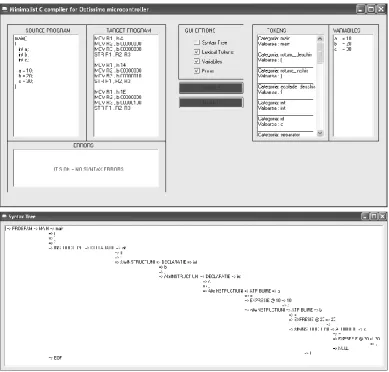
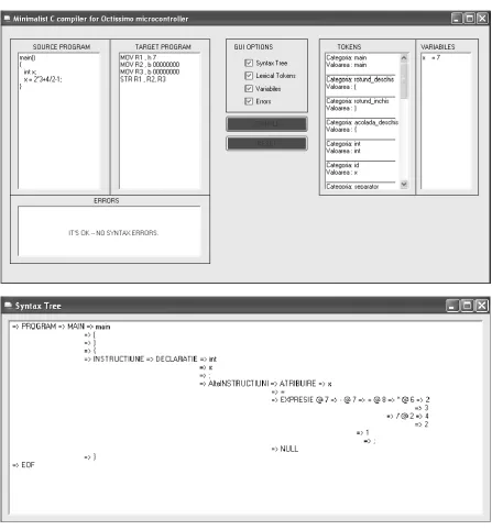
An example of using our application for a very simple program is shown in Figure 2. The graphical user interface allows (as it can be seen in the figure) the input of the source code (in the textbox on the left), as well as the visualization of the results (written in assembly language) and of the errors (in the bottom panel), and (on the right) the visualization of the program tokens and variables. The syntax tree can be seen as well by checking the corresponding checkbox on the main window of the application. It is shown in the bottom image in Figure 2. Figure 3 shows another example of use for the application.
The application is useful for didactic purposes, as it helps the user understand the basic concepts involved in implementing a compiler. The langugage is simplistic – it does not allow multiple data types or function calls. Nevertheless, it allows the implementation of various algorithms that manipulate integer scalar values (such as the computation of the greatest common divider or the computation of Fibonacci numbers).
Figure 3. The graphical user interface of the compiler showing the compilation of a sample program containing a numeric expression.
V. CONCLUSION
In this paper a compiler implementation was presented that did not require any code generation tools such as Lex and Yacc. The design and implementation steps are simplified and explained clearly in order to facilitate their understanding. A graphical user interface application that allows the user to input source code and visualize the intermediate steps performed when compiling that code was built.
The application is useful for didactic purposes, by facilitating the understanding of the methodology of manually implementing a compiler for a structured programming language.
The next step in developing our compiler is to introduce support for arrays and subroutines. The design methodology presented here can also be
extended to construct compilers for languages supporting other programming paradigms.
REFERENCES
[1] J. E. Hopcroft, R. Motwani, J.D. Ullman, Introduction to Automata Theory, Languages, and Computation (Second Edition), Addison-Wesley, 2001.
[2] P. Linz, An Introduction to Formal Languages and Automata (Third Edition), Jones and Bartlett Publihsers, 2001. [3] A.V. Aho, M.S. Lam, R. Sethi, J.D. Ullman, Compilers.
Principles, Techniques, & Tools (Second Edition), Pearson Education, 2007.
[4] K.D. Cooper, L. Torczon, Engineering a Compiler (Second Edition), Elsevier, 2012.
[5] D. Grune, K. van Reeuwijk, H.E. Bal, C.J.H. Jacobs, K. Langendoen, Modern Compiler Design (Second Edition), Springer Science+Business Media New York, 2012. [6] G. Evangelidis, V. Dagdilelis, M. Satratzemi, V. Efopoulos,
environment,” Proceedings of IEEE International Conference on Advanced Learning Technologies, 2001.
[7] D. Sarkar, O. Waddell, R. Kent Dybvig, “A nanopass infrastructure for compiler education,” Proceedings of the
ninth ACM SIGPLAN international conference on Functional programming, vol. 39 (9), pp. 201-212, September 2004. [8] A. Ghoulum, “An incremental approach to compiler