1
E1
ELECTRIC FIELDS AND CHARGE
OBJECTIVES
!
Aims
In studying this chapter you should aim to understand the basic concepts of electric charge and field and their connections. Most of the material provides illustrations which should help you to acquire that understanding. To test whether you have understood the concepts see if you can describe and explain the applications in your own words.
Minimum learning goals
When you have finished studying this chapter you should be able to do all of the following. 1. Explain, interpret and use the terms:
electric charge, coulomb, electron, electronic charge, conservation of charge, ion, electrostatic force, permittivity, permittivity of free space, conduction, electric field, field lines, field strength, uniform field, surface charge density, electrical shielding.
2. Describe a number of processes by which electric charges can be separated. 3. Describe the qualitative features of the interactions of static charges.
4. State and apply the relation between electric force and electric field.
5. Describe and explain examples of applications and hazards of electrostatic phenomena.
6. (a) Sketch electrostatic field-line diagrams for systems with simple conductor shapes including parallel plates, concentric cylinders, isolated sphere, parallel cylinders.
(b) Interpret given field-line diagrams in terms of magnitude and direction of the field.
7. State and apply the relation between the surface change density and electric field at the surface of a conductor.
8. Describe and discuss principles and examples of electrostatic shielding. CONCEPT DIAGRAM
Isolated charges Forces between charges
Coulomb's law
Electric field lines Electric fields
Fields and surface charges
Electrostatic shielding Separation of charges
Electric charge
Distribution of charges on
E1: Electric Fields and Charge 2
PRE-LECTURE!
1-1 INTRODUCTION
The natural world provides precious few clues to the ubiquity of electromagnetism. The properties of rubbed amber and the magnetism of lodestone were little more than curiosities until the 17th century. The elucidation of the nature of lightning and the recognition of light as electromagnetic radiation were even more recent. Yet our world is governed by electromagnetic interactions. All chemical bonds, the strength and weakness of materials, light, the influences that form and control living things are all aspects of electromagnetism. Indeed, only three other types of fundamental force are known: the weak force, the strong force and gravity.
Of these forces the first two, which are purely nuclear forces, are effective only over distances of less than 10-12!m - that is smaller than an atom. They are associated with radioactivity, but otherwise are of no consequence in chemistry and biology. Gravity is such a feeble force that it matters only in interactions involving bodies of ‘astronomical’ mass and is negligible in interactions between small things. Apart from the earth's gravitational pull, every force that you experience is electromagnetic in nature.
Electromagnetic force is associated with a fundamental property of matter - electric charge. No process is known which creates or destroys even the minutest amount of charge. This is formally stated as the law of charge conservation: electric charge can not be created or destroyed.
The SI unit of electric charge is the coulomb, symbol C. The magnitude of the charge on a single electron is a commonly used quantity in atomic physics. It is
e ≡ 1.6 ¥ 10-19 C.
Thus 1 C ≡ 6.2 ¥ 101 8 e.
The charge on an electron is -e, and on a proton, +e.
LECTURE
!
1-2 ELECTRIC CHARGE
Why study electrostatics?
Electrostatics is the basis of industrial processes such as electrostatic spray painting, and xerography, and of the unintentional build-up of electrostatic charge which can trigger explosions and fires in, for example, grain silos and operating theatres.
We study electrostatic phenomena in this course not simply to understand the applications of static charge, or the hazards they present, but because the ideas are applicable in other branches of electricity, and the electrical aspects of other sciences. The theory of electrostatics, electric charge, field and potential apply in more complex situations involving currents and magnetic fields.
Isolated electric charges and atomic structure
Demonstration
Isolated electric charges, such as those obtained by running a comb through your hair, can be detected with a field mill, an instrument which measures the charge induced on an internal sensing electrode. A field mill shows that the positive charge on the comb is balanced by a negative charge left behind on the hair.
Electrostatic phenomena are a consequence of the atomic nature of matter. All atoms are built up from three types of fundamental particles, protons, neutrons, and electrons, the properties of which are given in table 1.1. The nucleus of an atom consists of a number of protons and neutrons tightly bound together and surrounded by a cloud of electrons. The number of electrons in the
E1: Electric Fields and Charge 3 electron cloud is equal to the number of protons in the nucleus. Since the charges of the proton and electron are exactly equal in magnitude and opposite in sign, atoms are electrically neutral. Atoms may gain or lose electrons, thus becoming ions.
Particle Mass Charge
Proton mp + e
Neutron 1.01 mp 0
Electron 1
1840 mp
- e
Table 1.1 The fundamental particles of atomic physics
Atoms combine to form molecules, which in turn combine to form bulk material. The normal state of matter is electric neutrality: matter normally contains equal numbers of protons and electrons, and has no net charge. Electrostatic effects occur when this exact balance of positive and negative charges is disturbed, leaving a net charge of one sign on the body - i.e. electrostatic effects occur when electrical charges are separated.
Separation of electric charges
Charge can be separated by various means. Here are some examples.
• Contact of dissimilar materials is followed by physical separation (combing hair).
• The belt of a Van de Graaff generator carries charge. Here also dissimilar materials (the belt and the pulley) are contacted, and separated. Charge is drawn off the belt, and stored on the dome.
• In a battery charge is separated by chemical means.
• Diffusion of charge occurs in living cells. Ions of one sign of charge can move more readily through the permeable wall of a cell, than those of the other sign.
• Charge is separated by convection in thunderclouds.
All charge separation involves the expenditure of energy. The energy is released, for example in a spark, when the charged particles recombine.
1-3 FORCES BETWEEN CHARGED BODIES
Energy must be supplied to separate unlike charges because there is an attractive electrostatic force between the charges. This electrostatic force is one variety of the general electromagnetic force. It is the basic interaction between charged bodies and it is called electrostatic because the other varieties of electromagnetic force appear only when charges move.
Properties of the electrostatic force Experiments show the following.
• Like charges repel. If you connect somebody to an electrostatic generator their hair will stand up because each hair is carries the same sign of charge and the similar charges repel. Likewise, two foam plastic balls fly apart when both are positively charged.
• Unlike charges attract. When opposite charges are transferred to foam plastic balls, the balls are attracted towards each other.
• The magnitude of the electrostatic force between charges increases as their separation decreases.
E1: Electric Fields and Charge 4
Electrostatic force in atomic physics
The electrostatic force binds electrons and nuclei together to form atoms and the same force holds atoms and molecules together in bulk material. The strength of materials is due entirely to electric forces.
The electrostatic force is so potent that only minute deviations from charge equality can be achieved in practice. For example when a 0.2 kg aluminium plate is charged negatively by attaching it to a 250-volt battery, the charge on the plate is about -5 µC. To make up this huge charge requires that only 101 3 electrons, or 1 for every 101 2 of all the 102 5electrons on the plate, be added to the plate.
Electrostatic force in nuclear physics
The strong repulsive electrostatic force between the protons in the nucleus of an atom tends to break up the nucleus, which is held together by the very strong attractive nuclear forces. The collision of a neutron with a uranium-235 nucleus can break the nucleus into two lighter nuclei. These fragments are no longer held together by the short-range nuclear force, but move rapidly apart due to the repulsive electrostatic force between the protons in each nucleus. Thus the release of energy in nuclear fission is mediated by electrostatic forces.
1-4 ELECTRIC FIELDS
Electric field is an idea introduced to describe electric forces. In the TV lecture the dome of a charged Van de Graaff generator attracts charged droplets of water. This situation can be described by saying that the charge on the dome of the generator sets up an intense electric field, and the charged drops ‘feel’ a force when they are in the space occupied by that field.
A field is something that is defined at all points in a region of space. A familiar example is the gravitational field of the earth, which is often called the acceleration due to gravity (g). Another example is the velocity of water in a river which has different magnitudes and directions at different places. Examples to be considered in this unit are electric field, electrostatic potential and magnetic field. An electric field is said to exist at a point in space if a charged particle placed at that point experiences a force that would not be felt by an uncharged particle. We have already seen that a possible explanation for such a force could be the presence of another charged body - but that is not the only thing that can create an electric field. Instead of describing the interaction of charged particles directly in terms of forces it is more fruitful to use a new kind of description involving electric fields. The two descriptions are visualised and compared in figure 1.1.
A charged object creates an electric field.
The field acts on another charged object
to produce a force. E
q
F = qE A charged object exerts
a force on another charged object.
Figure 1.1 The concept of electric field
The diagram on the left represents the description of an interaction in terms of forces. On the right we separate the interaction into two parts.
E1: Electric Fields and Charge 5 The value of an electric field E can be defined in terms of the force F experienced by a particle with a small charge q:
F = qE . ... (1.1)
Both F and E are vector quantities - they have both magnitude and direction.* In this definition the magnitude of the force is equal to qE and the direction of the field is equal to the direction of the force on a positively charged particle. The force on a negative particle is opposite to the field direction. We say that an electric field is uniform when neither its magnitude nor its direction changes from one point to another.
The SI unit of electric field is called the volt per metre (symbol V.m-1) which is equivalent to a newton per coulomb (N.C-1).
1-5 FIELD LINES
A neat way of mapping a two-dimensional slice through a magnetic field is to float some grass seeds or some other kinds of small elongated objects on the surface of a liquid. The electric field causes the seeds to align themselves with the field's direction. An equivalent way of visualising a field in three-dimensions would be to imagine lots of tiny arrows, each one showing the direction of the field at the chosen place. There is, however, another way of visualising electric fields (and other vector fields) - field lines. Field lines are continuous directed lines drawn so that at any point on a line the direction of the line (its tangent) shows the direction of the field. Field line diagrams are also three-dimensional so it is not always possible to represent them accurately on flat diagrams. Figures 1.2 and 1.4 are examples where we can draw a two-dimensional picture because they represent situations which have the same configuration in all cross-sections.
Electrostatic field lines start on positively charged surfaces and end on negative charge (figures 1.2, 1.4). If you have an ‘isolated’ charged body the field lines go out to ‘infinity’ as though they are looking for the other sign of the separated charge (figure 1.8).
+ -
Figure 1.2 Field lines for two oppositely charged parallel cylinders
Not only do field line diagrams represent the field direction in a visually obvious way; the spacing of the lines also represents the magnitude of the field. The field is strongest where the lines are closest together.
* In printed material vectors are indicated by bold-face symbols, such as E. In manuscript we usually put a tilde (~) under the symbol (e.g.
~
E ) or an arrow above it (e.g. ÆE ). The magnitude of a vector is indicated by using the same symbol without bold-face or by omitting the tilde or the arrow. Occasionally a component of a vector is indicated in the same way as a magnitude; the context usually makes it clear which is meant.
E1: Electric Fields and Charge 6
1-6 ELECTRIC FIELD AND CHARGE
Conductors with static charges
An electrical conductor is an object through which electrons or ions can move about relatively freely. Metals make good conductors. If a net charge is placed on a conductor and it is then left alone, the charge very quickly settles down to an equilibrium distribution. There are several interesting things to note about that situation. (See figure 1.3.)
• The net charge is spread out over the surface of the conductor, but not uniformly. • There is an electric field in the space around the conductor but not inside it.
• At points just outside the surface of the conductor, the electric field and the electric field lines are perpendicular to the surface.
Figure 1.3 Electrostatic field near the surface of a conductor
The charge density varies over the surface. The field near the surface is strongest where the charge density is highest.
Figure 1.4 Electric field between a positively charged cylinder and a nearby plane surface.
We can describe the way that charge spreads out on the surface by specifying the concentration of charge or surface charge density - the charge per surface area. The magnitude (E) of the electric field at the surface of a conductor is proportional to the surface charge density (s). This relation is usually written as
E= s
e . ... (1.2)
The constant e is a property of the medium that surrounds the conductor, and is called the permittivity of the medium. If the surrounding space is empty (a vacuum) we indicate that by putting e = e0, and we call the constant e0 (pronounced ‘epsilon nought’) the permittivity of free space. Although a vacuum is a pretty rare thing, the permittivity of air is very nearly equal to e0, so in electrostatics we usually regard air as being equivalent to empty space.
E1: Electric Fields and Charge 7 The SI unit of surface charge density is the coulomb per square metre (C.m-2). The SI unit of permittivity is called the farad per metre, F.m-1 which, in terms of units that you know already, is equivalent to C2.N-1.m-2. The permittivity of free space is one of the fundamental constants of nature; its value is
e0 = 8.85 ¥ 10-12F.m-1
.
Equation 1.2 (with e = e0) is always true for conductors in a vacuum. It is a consequence of Gauss's law, which is one of the four basic laws of electricity.
Field lines and electric field strength
Field line diagrams represent the strength of the field at each point provided that they are correctly drawn. In a correctly drawn field-line diagram each line must begin (and end) on equal amounts of charge. The field lines are also drawn so that the field strength is proportional to the concentration of the lines (figure 1.5).
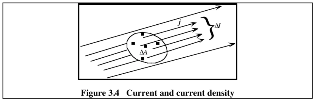
Think of a small imaginary surface, area A, drawn perpendicular to the field at some place in space. Count the number, n, of field lines that go through the surface. Then the magnitude of the electric field averaged across the area A is represented by the number of field lines per area.
E µ n
A . ... (1.3)
Thus, as the field lines spread out from a charged body the electric field strength falls off
correspondingly. Figure 1.5 Field strength and
concentration of field lines
The product of the component of the average field perpendicular to the surface and the surface area is called the flux of the field through the surface. So the number of field lines through a surface represents the flux of the electric field through that surface.
In principle once a charge distribution is known the electric field can be deduced and vice versa. In practice such calculations can usually be done only numerically (by computer) except for simple geometries. Calculations of the relationship between electric field and charge distribution are vital in many branches of science and technology. Examples range from the study of ion diffusion in living cells, through the design of electrical equipment, to the investigation of thunderstorms.
For highly symmetrical conductors accurate field-line diagrams are fairly easy to draw. Some examples are given in figures 1.6, 1.7 and 1.8.
Figure 1.6 Field lines for parallel plates
The fringing field at the ends of the plates can be ignored if the plate area is large, or if the plates are close together.
E1: Electric Fields and Charge 8 + + + + + + + + + + + + + + + + + + -
-Figure 1.7 Coaxial cylinders The field lines are radial.
+ ++ + + + + + + ++ + + + + + + +
Figure 1.8 Charged metal sphere The field lines are radial in three dimensions. This diagram shows a two-dimensional slice through the
centre of the sphere.
1-7 ELECTROSTATICS IN INDUSTRY AND COMMERCE
Electrostatic spray painting
If a surface to be coated is charged, say negatively, then the corresponding electric field will be directed inwards towards the surface. Positively charged droplets of paint from the sprayer are then driven towards the surface by the forces that they experience in this electric field (or, if you like, the positively charged droplets are attracted to the negatively charged surface).
Electrostatic precipitators
In electrostatic dust precipitators a large negative charge is maintained on spiral wire electrodes, which are arranged between positively charged plates. Negative ions (O2-, N2- etc.) are formed at the wire and the exhaust gases pass between the wires and the plates. The negative ions collide with the dust particles, giving them a negative charge. This negatively charged dust is then driven by the electrostatic field to the positive plate, to which it adheres until collected. Electrostatic precipitators are routinely used in coal-fired power stations; they remove over 95% of the light fly ash from the exhaust gases.
Xerography
In a photocopier an image of the document is formed on a charged plate of selenium - a photoconductive material. Light reflected from the white areas of the document discharges the illuminated areas of the plate, leaving a charge-image of the document. Charged particles of black printing ink are then attracted to the charged image. Finally, the ink is transferred by direct contact to the sheet of oppositely charged copy paper.
1-8 ELECTRICAL SHIELDING
Michael Faraday discovered that inside a closed metal room no electrical effects from outside influences could be detected, no matter how violent the electrical activities outside. As he put it:
‘I went into the cube and lived in it, and using lighted candles, electrometers, and all other tests of electrical states, I could not find the least influence upon them ... though all the time the outside of the cube was powerfully charged, and large sparks and brushes were darting off from every part of its surface.’
[From M. Faraday (1849), Experimental Researches in Electricity para. 1174.]
Demonstration
Faraday's demonstration is repeated in the TV lecture where one lecturer stands inside a wire mesh cage. A potential difference of 40 kV is established between plates on each side of the
E1: Electric Fields and Charge 9 cage; the cage rises to a voltage of about 20 kV. Despite the intense electric fields that exist
outside the cage, the lecturer is quite safe inside the cage. Indeed, no electric field can be detected inside.
When a hollow conductor is placed in an electric field, charge is redistributed very rapidly over the surface so that the field lines end on surface charges (figure 1.9).
- - - - - - - - - + + + + + + + + +
Figure 1.9 Surface charges on a hollow conductor in an electric field
There is no field within the conducting walls, and hence there is no field inside the hollow space. Of course charge, inside the hollow conductor, can be separated to give an electric field inside the conductor. The point is that no external electric field can influence the electrical conditions inside the conductor. The inside of the conductor is shielded from outside influences. In practice shielding is never absolutely effective, but it can reach 99.99% effectiveness even with mesh rather than continuous metal. Attention must be paid to the integrity of joins, to doors and to the entry of cables. In the TV lecture, it is shown that the field inside the cage, as measured by the field mill, is hundreds of times less inside the cage than outside. Note that a battery operated field mill was used to avoid the problems of bringing in power leads while maintaining complete shielding.
For successful shielding of experimental apparatus, the whole apparatus including signal and power leads, must all be totally within the same shielded space. Provided that the shield encloses the entire experiment it may be any shape. A mesh shield will also protect apparatus from changing fields of electromagnetic radiation, as long as the mesh size is very much smaller than the wavelength of the radiation. In the TV lecture, it is demonstrated that the mesh cage effectively screens broadcast band radio signals (about 300 m wavelength), but not light (500 nm).
A screened room is a normal feature of any electrophysiology laboratory, where tiny voltages are measured. In other situations screening may be necessary because the external fields are so strong. In plasma physics experiments, for example, huge electrical energy is used to form the plasma so the apparatus which makes sensitive measurements of the electrical properties of the plasma must be thoroughly shielded.
Correctly screened Incorrectly screened
Figure 1.10 Screening an experiment If the screen is in two or more disconnected parts, it is ineffective.
E1: Electric Fields and Charge 10
POST-LECTURE!
1-9 THE FUNDAMENTAL LAWS OF ELECTROSTATICS
Traditional courses on electrostatics start with the inverse square law for the force between two point charges q
1 and q2, Coulomb's law:
F = 4π1e 0
q1q2
r2 .... (1.4)
where r is the distance between the charges, and the force acts along a line joining the charges. The corresponding expression which gives the magnitude of the radial electric field of a point charge, q, (or of a uniformly charged sphere) is
E = 4π1e 0
!q!
r2 ....(1.5)
where r is the distance from the charge (or the centre of the sphere) and the electric field is in a radial direction.
While this law is of fundamental importance in physics, it is not used in this form either in the later development of electromagnetism, or in the life sciences. Consequently we have based this course on a much more useful law which is equivalent to Coulomb's law: Gauss's law. Although we have not formally stated Gauss's law (it is rather abstract mathematically) we have used two aspects of it.
i) The field near a conducting surface is proportional to the surface charge density (eqn 1.2). ii) At any place the electric field strength is proportional to the areal density of field lines (eqn
1.3).
Field Lines and Gauss's law
Like many very basic physical laws, Gauss's law appears in many guises, which may be very mathematical. The formal statement of Gauss's law is: ‘The total flux of electric field through any simple connected closed surface is equal to the total charge enclosed by that surface, divided by e0.’ (Flux is a product of field strength and area of an imaginary surface drawn perpendicular to the field.)
We can also express Gauss's law in terms of field lines: ‘The total number of field lines passing outward through any closed surface is proportional to the total charge enclosed within the surface.’ This statement implies that field lines originate on charges. Field lines passing out of the surface add to the number of lines; those passing into the surface subtract from the number of lines. Superposition
We have assumed, correctly, that electric fields are additive. Physical quantities which behave additively, like fields, are said to obey the principle of superposition. This is not a trivial statement because there are some quantities, such as intensity of coherent waves and the effects of drug dosages, which do not behave additively. Physical quantities which do obey the superposition principle include force, mass, energy, electric field, magnetic field and electrostatic potential.
Electric dipoles
A pair of oppositely charged particles is often called a dipole. The electric field produced by a dipole is like that shown in figure 1.2. One way of describing the properties of a dipole is to specify its dipole moment, which is defined as the product of the magnitude of the charge and the separation between the particles: p = qd.
E1: Electric Fields and Charge 11
1-10 ELECTROSTATIC DEFLECTION
A good example of the force experienced by a charge in an electric field is provided by the technique of electrostatic deflection. Consider an electron of mass m and horizontal velocity v entering a region of vertical (upward) electric field E in a vacuum (figure 1.11).
Electron
beam Electric field E
Figure 1.11 Deflection of an electron beam by an electric field
The electron will undergo an acceleration of magnitude eE/m. Since the electron's charge is negative the direction of this acceleration is opposite to the direction of the field. The component of velocity parallel to the field increases in magnitude while the component perpendicular to the field remains constant. The result is a motion in which the path bends rapidly toward the (negative) field direction. The path is like that of a projectile which is thrown with an initial horizontal velocity and bent downwards by the earth's gravitational field.
N o t e
To analyse the motion, use two components. Displacement component x is perpendicular to the field, to the right in figure 1.11, and component y is parallel to the field lines (up). Since a typical electrostatic force is so strong compared with gravity, we leave gravity out of the analysis.
The x-component of the motion is force free, so the component of velocity vx maintains a constant value v and the horizontal displacement in a time interval t is
x = vt.
The component of motion parallel to the field is affected by a constant force component
Fy =- eE. This force produces a constant acceleration component ay given by the equation of
motion, Fy = m ay. To find the velocity component, integrate (find the area under) the acceleration-time graph. That gives
vy = ayt
Then you draw another graph, the velocity time graph, to find y. The result is
y = - 1 2Ë Ê ¯ ˆ eE m t 2
To find an equation for the shape of the path, eliminate the timefrom the equations for x
and y. y = - 1 2Ë Ê ¯ ˆ eE m E 1 v2 x 2
The electron thus follows a parabolic path in the field.
Demonstration
The path is demonstrated in the next TV lecture, E2. A special electron beam tube has a longitudinal phosphorescent screen which reveals the path of the ribbon-like electron beam. The vertical Efield is produced by putting a high potential between a pair of horizontal plates inside the tube.
Electrostatic deflection of electron beams is used in cathode ray oscilloscope tubes to make electrical measurements. Amplified signals are applied to horizontal and vertical deflector plates inside the tube, both to provide the time base sweep, and to display the signal under investigation.
E1: Electric Fields and Charge 12
1-11 QUESTIONS
Q 1 . 1 Why do you think it took people so long to formulate the notion of electric charge, whereas mass has been recognised since antiquity?
Q 1 . 2 If you pass a comb through your hair and it acquires a charge of -0.1 µC, how many excess electrons does it carry? What conclusions can you reach by applying the law of conservation of charge to this situation?
Q 1 . 3 Which of the following effects are fundamentally electric in nature? Discuss each briefly. 1. tension in a spring,
2. gas pressure,
3. ‘crackles’ from some very dry garments when you undress,
4. ‘crackles’ from treading on dry leaves, 5. gravity, 6. nerve conduction, 7. nuclear fission, 8. the aurora, 9. radioactive b decay, 10. centrifugal force,
11. the spiral structure of galaxies, 12. moment of inertia,
13. ‘magnetic’ photo albums.
Q 1 . 4 A charged object, such as the dome of a Van de Graaff generator, is discharged by momentarily touching it with an earth wire. Draw diagrams of the charge and fields involved, and explain what is going on here.
Q 1 . 5 A spray-painter nozzle normally produces droplets of paint in a cone shaped beam of width 30˚. What do you think would be the effect on the beam if each droplet were given a large positive charge as it left the nozzle? Give your reasons. [Hint: remember that the separation of the droplets increases as they move away from the nozzle.]
Q 1 . 6 A petrol fire at a filling station was allegedly caused by ‘static electricity’. Explain what this claim means, and outline the investigation that a forensic scientist might make to establish whether or not static electricity could have been the cause of the fire.
Q 1 . 7 A cell membrane has a surface charge density of -2.5!¥! 1 0-6! C . m-2on the inside surface and +2.5!¥! 1 0-6! C . m-2 on the outside. The thickness of the membrane is much less than the size of the cell. Ignore any dielectric polarisation effects.
a) Sketch the electric field between these charge layers. b) Calculate the magnitude of the electric field
(i) within the cell membrane, (ii) inside the body of the cell.
This problem, and other similar problems, will be discussed in later sections of this course.
Q 1 . 8 In the previous problem, what electric force would be experienced by a singly ionised ion of sugar? Compare this with the gravitational force on the same ion.
Data required:
Relative molecular mass of sugar ion = 343
Electronic charge = 1.6 ¥ 10-19 C Mass of proton = 1.67 ¥ 10-27kg Magnitude of gravitational field = 9.8 m.s-2
Q1.9 a) Sketch the electric field between two concentric cylinders of radii r
1 and r2 and length h. The charges +Q and -Q on these cylinders are equal in magnitude, but opposite in sign.
b) Obtain an expression for the magnitude of the electric field at a point between these cylinders, at a distance
r from their common axis.
Q 1 . 1 0 A 2.0 m long cylinder, 0.50 m in diameter, has a charge of 2.0 ¥ 10-3 C uniformly distributed over its curved surface.
a) Calculate the electric field at the curved surface of the cylinder. b) What is the electric field 0.75 m from the axis of the cylinder?
Q 1 . 1 1 An experiment is planned which involves the measurement of very small potentials from living fish (in water). Indicate how the requirements for thorough electrostatic shielding might influence the choice of equipment and the configuration of the apparatus.
Q 1 . 1 2 A one-cent coin and a twenty-cent coin are placed about 10 cm apart on a sheet of glass. The 1 c coin bears a charge of +Q and the other coin, -Q. Sketch the field lines in the vicinity of the coins. Where will the electric field be strongest?
13
E2
ELECTRIC POTENTIAL
OBJECTIVES
!
Aims
The most important new concept that you should aim to understand from this chapter is the idea of potential difference. Associated with this you will learn how to use the concept of energy in the study of electrostatic phenomena. You will also learn the essential physics involved in the electrical behaviour of non-conducting materials, called dielectrics, using the concepts (which have already been introduced) of charge, charge density and electric field.
Minimum learning goals
When you have finished studying this chapter you should be able to do all of the following. 1. Explain, interpret and use the terms:
induced charge, electric potential, voltage, potential difference, electromotive force, volt, charge double layer, potential discontinuity, capacitance, capacitor, dielectric, relative permittivity, equipotential, equipotential surface, potential gradient.
2. Give examples of the magnitudes of typical voltages encountered in scientific work and everyday life.
3. State and apply the relations among potential difference, surface charge density, charge, surface area, relative permittivity and separation distance for parallel plate capacitors and charge double layers.
4. State and apply the definition of capacitance. Describe and explain the effect of dielectric materials on capacitance.
5. State and apply expressions for the energy stored in a capacitor.
6. State and apply the relation between potential difference and electric field strength for uniform fields.
7. Apply energy conservation to the motion of charged particles in electric fields. 8. (a) Interpret equipotential diagrams.
(b) Sketch equipotentials for simple geometries of charged static conductors. (c) Explain why the surfaces of conductors are usually equipotentials.
E2: Electric potential 14
PRE-LECTURE!
2-1 INTRODUCTION - ELECTRIC POTENTIAL
In chapter E1 you saw that one way of explaining the effect of a static distribution of charges is to describe the electrostatic field E in the space around the charges. In this chapter we explore another way of doing the same thing - which is to describe the electric potential difference between various points in the space. These two kinds of description are essentially equivalent - if you know one of them you can work out the other. The relation between electrostatic field and potential difference is the same as that between conservative force and potential energy (PE); see chapter FE5. The change in PE is equal to minus the work done by the force. Since electric field is force per charge, potential difference can be defined as a change in potential energy per charge.
One of the advantages in talking about potentials rather than electric fields is that whereas force and electric field are vector quantities, potential energy and potential are scalar quantities. Scalars are more easily calculated and described than vectors.
2-2 INDUCED CHARGE
Consider what happens when a body is introduced into a region of electric field, for example by bringing a charged object close to the conducting body. If the body is a metallic conductor some of the electrons in it are free to move. They move in a direction opposite to that of the electric field, leaving a positive charge behind them. We say that charges have been induced on the ends of the body by the electric field. Charge separation can also be induced in insulating materials when positive and negative charges within the molecules of the material rearrange themselves, leaving net surface charges of opposite sign on opposite sides of the conductor. Such induced charges are formed when pieces of paper are attracted to a charged comb. See figure 2.1
Figure 2.1 Induced charge
Question
Q 2 . 1 The charges induced on a piece of paper by an external electric field are equal in magnitude and opposite in sign, and yet the paper is still attracted to a comb (figure 2.1). Why?
- +
- + +
Field without the conductor Same field with the conductor
E2: Electric potential 15
The original field lines are distorted by these separated charges (figure 2.2). Some of them terminate at the surface on one side of the body, and new field lines originate from the other side. If the body is elongated the separation between the charges can be quite large i.e. the charges act, effectively, as isolated electric charges.
LECTURE
!
2-3 ELECTRIC POTENTIAL
Any charged particle located in a region of electrostatic field experiences a force. The force on the particle at any place is determined by the particle's charge and the value of the field: F = qE. If the particle moves from one place to another within that region, the electrostatic force does work on the particle and its potential energy changes. Just as we can associate an electric field with each point in the space, we can also define an electrical potential V for every point, such that a charged particle's potential energy U at the point is given by the simple relation
U = qV. ... (2.1)
Since potential is defined at each point in space it is a field, but unlike the electric field E, it is a scalar so it has no direction. Since potential energies are always reckoned from an arbitrary zero level, so is potential. It is usually more meaningful to talk about the potential difference (∆V) between two points in space than the potential (V) at one point.
The colloquial term ‘voltage’ can refer to one of two distinct physical ideas - EMF or potential difference. EMF is associated with sources of electrical energy while potential difference is created by distributions of charge. (The term EMF is derived from electromotive force, a name that is no longer used, because the quantity is not a force.)
Electric potential and sources of electric energy
Sources of electrical energy such as batteries and sources of electrical signals such as nerve cells can separate electric charges by doing work on them. This energy put in to a system of charges can be described in terms of the ‘voltage’ or EMF of the source. For sources of electricity:
EMF = charge!passed!through!source .energy!supplied!by!source
The separated charges produce an electrostatic field and a potential at every point in the space around them.
When a source of EMF is not connected to an external circuit, the potential difference between its terminals becomes equal to the EMF of the source, but while charges are actually flowing through the source energy dissipation within the source may cause the potential difference to be less than the EMF. This point is explored in more detail in your laboratory work.
The SI unit of both potential difference and EMF is the volt; (symbol V) defined as one joule per coulomb: 1 V ≡ 1 J.C-1. The unit is named after Alessandro Volta who astonished the scientific world in 1800 when he invented the first source of continuous electric current, the first battery.
Voltage is probably the most commonly used term in electricity. That is because the most significant thing about any source of electricity or about any electrical signal is its voltage or EMF. Some examples are listed in the following table.
E2: Electric potential 16
Source Voltage (EMF)
EEG signals ~ 1 µV
ECG signals ~ 1 mV
cell membrane ~ 100 mV
flashlight cell 1.5 V
domestic electricity 240 V (Australia, U.K.) 115 V (U.S.A., Canada)
Van de Graaff generator 105 V
power transmission 3.3 ¥ 105 V
thunderstorm > 108 V
2-4 ELECTRIC FIELD AND POTENTIAL
You have already seen that electric field is force per charge and potential is potential energy per charge. So electric field and potential are linked in the same way that the concepts of force and potential energy are linked. You will recall, from chapter FE5, that change in potential energy is defined as the negative of the work done by a conservative force, ∆U = - ∆W. You should also remember that to calculate work done by a given force, we integrate the force with respect to displacement or, equivalently, find the area under a force-displacement graph. So the way to calculate potential difference from electric field is the same: integrate the field with respect to displacement. It is worth recalling why this straightforward relation works. It is because nature has provided a special class of forces, conservative forces, for which the work done by the force on a particle depends only on the starting and finishing points of its motion. The details of the path between the points don't affect the amount of work done. The electrostatic force happens to be one of those conservative forces, so the work that it does on a particle, and hence also the work per charge, depends only on the starting and finishing points. That is why potential can be defined uniquely at each point in space.
Figure 2.3 Work done by a uniform field
The total work done by the electrostatic force is the same in both cases.
In a course like this we don't do complex mathematical problems, so we need consider only a simple but surprisingly useful example: the case of a uniform electric field (figure 2.3). Suppose that we have a particle, charge q, which goes from A to B as shown in the left hand part of figure 2.3. (An external force would be needed to achieve that, but we are not really interested in that aspect.) The size of the electrostatic force on the particle is equal to qE and it is directed to the right. Since the field is uniform the force doesn't change and the work done by the electrostatic force is just the product of the displacement and force's component in the direction of the displacement (which is negative in this example).
E2: Electric potential 17
W = -qEl .
Since the change in PE is equal to minus the work done by the electrostatic force
U
B-
U
A=
qEl
.
Finally the potential difference between points A and B is the change in PE per charge, i.e.
VB-VA =El . ... (2.2)
In this example point B is at a higher potential than A. One way of seeing that is to note that you, an external agent would have to do work on a positively charged particle in order to push it from A to B against the electrostatic force.
Now suppose that instead of going straight from A to B, the particle went via point C, as shown in the right-hand part of figure 2.3. On the diagonal part of the path, the magnitude of the force component is less but the displacement is longer. It's actually quite easy to show that the work is the same as for the path AB. On the second stretch, from C to B, the component of the force in the displacement direction is zero, so there is no more work. The work done over the paths AB and ACB is identical. In fact it is the same for all possible paths from A to B. In this example we have actually shown that the potential at C is the same as that at B. Furthermore it's the same at all points on the line BC. We can call the line BC an equipotential.
The relation between potential and field (equation 2.2) can be looked at in another way. We can express the component of the electric field in terms of the change in potential and the displacement.
For a uniform field: Ex = -DV
Dx ;
or more generally Ex =
-dV dx
. ...(2.2a)
This relation says that the x-component of the electric field is equal to the negative of the gradient (in the x-direction) of the potential. (That's not surprising because we got the potential by taking the negative integral of the work per charge.) The sign is important here because we are now talking about a component of the field, rather than its magnitude, and we need to take account of the directions of both field and displacement.
This relation is also the origin of the SI unit name, volt per metre, for electric field strength.
2-5 CONDUCTORS
Conductors as equipotentials
Every part of a conductor (which is not carrying a current) is at the same electric potential. The conductor is an equipotential region and its surface is an equipotential surface. If the distribution of charges near the conductor is changed, the conductor will always remain an equipotential, although the value of that potential depends on the charge on and near the conductor.
To see why conductors are equipotentials, suppose we have a one that is not an equipotential. In that case there would then be an electric field in some part of the conductor and the free charges would immediately be accelerated by the electric field. The result would be a continual redistribution of the charges in the conductor until the internal field was reduced to zero.*
A current-carrying conductor (e.g. a wire) by contrast is not strictly speaking an equipotential; there must be some potential drop along the direction of the current in order to keep the charges flowing. However in many applications, the potential change along the conductors is much less than that across the generator or the load. To that extent even current carrying conductors may be regarded as equipotentials. It is common practice to regard the earth conductors in circuits as
* In fact this redistribution occurs extremely rapidly; the fields fall exponentially to zero with a time constant!!=!e/g where g is the conductivity of the material (see chapter E3). For copper, as an example, the relaxation time t is about 10-19 s. Even for relatively poor conductors like rock or living tissue, the relaxation time is much shorter than 1 µs.
E2: Electric potential 18
equipotentials (at zero volts). Sometimes this is not good enough, and one is faced with earth loop problems: spurious signals arise in amplifiers due to neglected currents in, and potential drop along, the earth conductors.
In the design of electron guns in (for example) electron microscopes, explicit use is made of the fact that conductors are equipotentials. Potentials applied to the electrodes of the gun establish the electric field which accelerates the electron beam (see chapter E3).
Pairs of conductors
For a pair of conductors, each of which is an equipotential, the potential difference is related to the electric field between them. Indeed, either potential or field can be used to specify the electric state of the conductors. A simple example is a pair of plane parallel conductors (figure 2.4)
+ + + + + + + + + + + + + + + + + + + + + + + + + + + + + + + + + + + + + + + + +
-Strong uniform field between plates
Weak fringing field outside Equipotential
Equipotential
Figure 2.4 The electric field of charged parallel plates
When the plates are charged, positive on one and an equal negative charge on the other, the charges spread out uniformly over the inside surfaces of the plates. The electric field, represented by field lines running from the positive to the negative charges, is approximately uniform between the plates. By making the plates sufficiently close, the non-uniform fringing field at the edges becomes relatively unimportant. The field (and field lines) are perpendicular to the plates because the plates are conductors (see chapter E1). The symmetry of the arrangement ensures the uniformity of the field (represented as equally spaced parallel field lines everywhere normal to the surface of the plates).
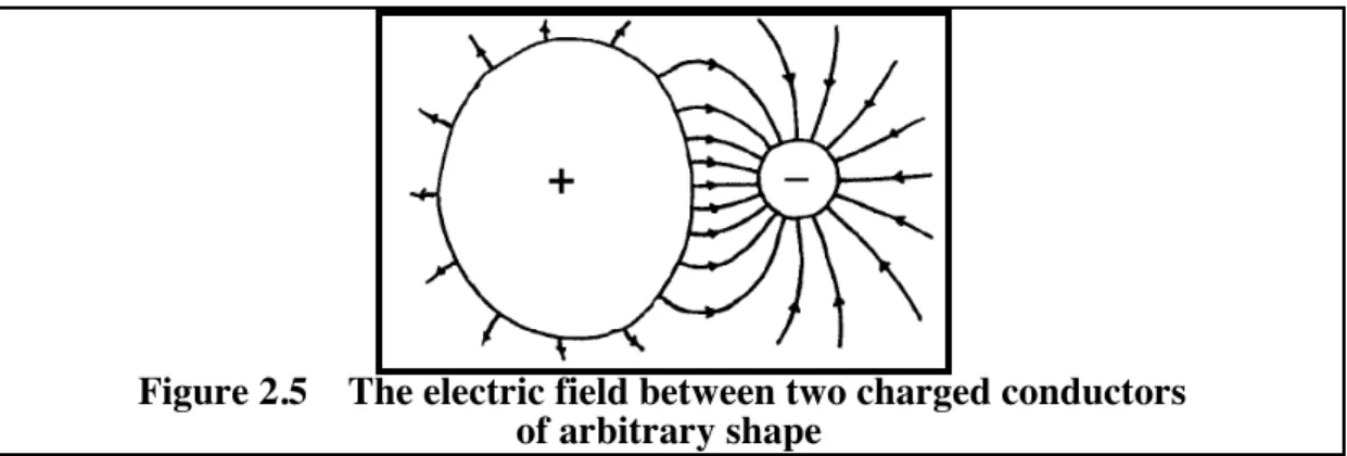
We have already discussed the connection between field and potential for the case of a uniform field. The electric field between the plates is equal to the potential difference between them divided by their separation. For conductors of arbitrary shape (figure 2.5) the electric field between them is non-uniform.
+
_
Figure 2.5 The electric field between two charged conductors of arbitrary shape
The point to be remembered is that there is a unique electrostatic potential between any pair of conductors.
Demonstration
In the video lecture, the voltage between two conductors is measured with the voltmeter leads touching the conductors at several different pairs of points. The voltage is shown to be independent of the location of the voltmeter probes.
E2: Electric potential 19 Demonstration
A demonstration of the electrostatic deflection of a beam of electrons which occurs in the video lecture is pertinent to chapter E1. See §1-10.
2-6 ELECTRIC DOUBLE LAYERS
Two closely spaced layers of charge, equal in magnitude and opposite in sign, comprise a charge double layer. Such double layers occur in the membranes of all living cells. An understanding of their electrical properties is essential in studying the mechanism of nerve transmission and cell metabolism. Here we consider the simplest type of double layer, where the layers of charge are on parallel plane conductors. By supposing that the areas of the two plane conductors are very large, on the scale of their separation, the mathematical description becomes very simple, but the physical ideas involved apply equally well to other shapes and areas of double charge sheets.
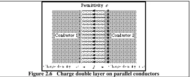
Consider two conductors having plane parallel faces a small distance l apart and charged with surface charge density of magnitude s. The material in the space between the conductors has permittivity e (figure 2.6).
Figure 2.6 Charge double layer on parallel conductors
The conductors are sufficiently close so that the effects on the non-uniform field at the edges may be neglected. Then the double layer has the following properties.
• Between the charge layers, the magnitude of the electric field is uniform, directed from the positive towards the negative charges, and of strength (given by equation 1.2)
E = se ....(2.3)
i.e. the lines of E terminate on the charges according to Gauss's law.
The electric field is perpendicular to the conductor surface - can you see why? The magnitude E of the field does not depend on the separation l.
• Within the conductors, the electric field is necessarily zero. Each conductor is an equipotential region.
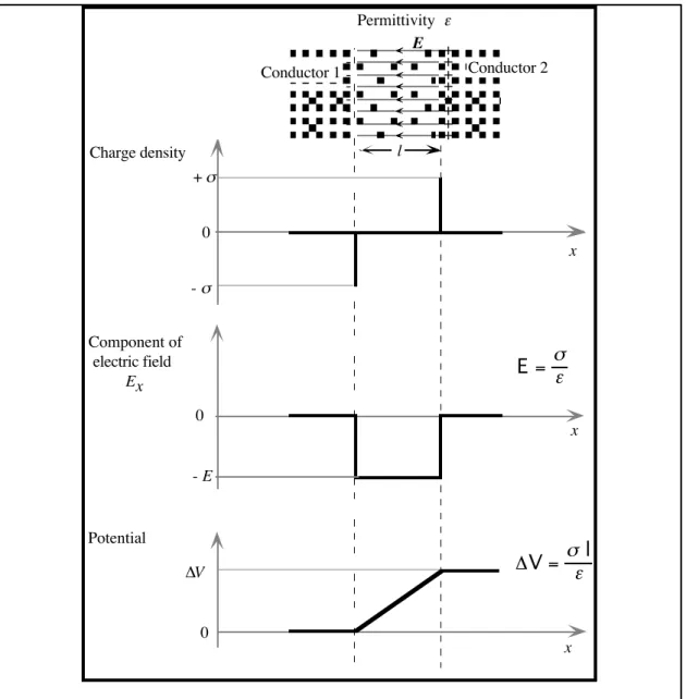
• There is a potential difference between the two conductors given by
∆V = El = sel .... (2.4)
In figure 2.6, conductor 2 is at the higher potential since it is positively charged. For fixed amounts of charge, ∆V increases as the spacing l increases.
• Often the spacing l is very small, and we are not very concerned with the region inside the double layer. In effect the charge double layer represents a potential discontinuity between the two conductors. In fact, whenever a potential difference exists between two contiguous pieces of matter a charge double layer is involved. Examples include living cells, batteries, thermocouples, semiconductor junctions, etc.
E2: Electric potential 20 - + - + - + - + - + - + - + - + Conductor 1 Conductor 2 l Permittivity e - s Charge density + s 0 Component of electric field Ex 0 - E Potential ∆V 0 DV= sel E = se x x x E
Figure 2.7 Charge, field and potential in a double layer The horizontal axis in all cases represents position.
The properties of a charge double layer are depicted in the graphs of figure 2.7. These diagrams illustrate that a charge layer represents a discontinuity in the electric field of magnitude es
0
. A charge double layer represents a discontinuity in the potential, of magnitude sel
0 . Demonstrations
Some of the properties of charge double layers are demonstrated in the video lecture.
i) The field mill is mounted with its measuring aperture flush with the surface of an aluminium plate of diameter 0.70!m. A second plate, supported by a high quality insulator is held 0.05!m from the first plate.
The insulated plate is charged by momentarily connecting a 50 V battery between the plates. The field mill meter reads 1 kV.m-1 (50 V ÷ 0.05 m). The field between the plates is 1!kV.m-1 as the plates are close and edge effects are comparatively small. Thus the magnitude of the surface charge density on the plates is uniform and is related to the electric field by equation 2.3.
The separation of the plates is increased, keeping the charge and the charge density constant. The meter continues to read 1!kV.m-1 confirming that E is indeed independent of the separation. (The slight fall in E is due to the increasing significance of the edge effects as the separation increases.)
ii) The same aluminium plates were placed very close together (about 1 mm) and charged by momentary contact with a 250 V battery. The plates were then drawn apart slowly. An electrostatic voltmeter connected between the plates showed that the potential rose as the plates
E2: Electric potential 21 were separated, more or less in proportion to the separation. The potential rose to above 8 kV
when the plates were well separated.
This is consistent with equation 2.4 which shows that the voltage increases with separation if the charge is kept constant. In this demonstration the separation l was increased about 30 times, and the voltage rose in essentially the same ratio from 250 V to 8 kV.
2-7 CAPACITANCE
Definition of capacitance
If separated charges +Q and -Q are placed on a pair of conductors, then there will be a potential difference V between the conductors. (Note that here V means the same as ∆V.) Unless the material between the conductors breaks down and starts to conduct the potential difference is found to be proportional to the charge. So the ratio
C = QV ... (2.5)
is a constant called the capacitance of the pair of conductors. The capacitance depends only on the shapes of the conductors, their separation and the composition of the insulating material between them. It does not normally depend on the voltage or the charge.
The name capacitance is a modernised version of the old name capacity which expresses how much separated charge a capacitor can hold in terms of the voltage. In the old days capacitance used to be measured in units of jars because the first capacitors were glass jars coated inside and out with metal foil. The SI unit of capacitance is the coulomb per volt, which has the special name of farad (symbol, F). In most laboratory work we deal with capacitances in the range of 1 pF (10-12 F) through 1 nF (10-9F) to 1 µF (10-6F) and beyond. One microfarad is a decent sized capacitance.
Parallel plate capacitor
Mathematically the simplest kind of capacitor consists of two identical flat sheets of metal separated by a thin layer of insulating material. When the capacitor is charged we have a charge double layer for which the potential difference is given by equation 2.4:
V = sel .
Combining this equation with the definition of surface charge density (s = Q / A) and the definition of capacitance (equation 2.5) gives a formula for the capacitance:
C = elA . .... (2.6)
You can now see where the unit for permittivity, F.m-1, comes from. Just put F for capacitance, m2 for area and m for separation into equation 2.6.
Equation 2.6 is a special case of the general result that, for any pair of conductors
C = eËÁÊspacing area ¯˜ˆ ¥ F ... (2.7) where F is a dimensionless factor (a pure number) that depends on the actual shapes and arrangement of the conductors. For the parallel plate capacitor, F = 1.
The effect of a dielectric
It is shown in the video lecture that if a parallel plate capacitor is charged, and then a sheet of perspex is inserted between the plates the voltage across the capacitor falls.
Since for a capacitor V = QC and in this case the charge does not change, it follows that the effect of the perspex is to increase the capacitance. The effect is already predicted by equation 2.6 if we say that the permittivity of perspex is larger than that for air. In general, capacitance is increased if an insulating material replaces vacuum between the plates. A material that produces this effect is called a dielectric.
E2: Electric potential 22
Figure 2.8 Effect of a dielectric on a charged capacitor
The effect of the perspex can be understood by considering its molecular structure. The electron clouds are bound to their respective molecules to the extent that they are not free to flow through the material (in contrast with conductors). When the perspex is placed in the charged capacitor, those electron clouds are displaced slightly by the electric field within the capacitor. In the bulk of the material there is no average effect as the charge induced on one end of a molecule is cancelled by the charge of opposite sign induced on the end of the adjacent molecule, but bound
surface charges appear on the surfaces. Each molecule behaves like a dipole and the dipoles are aligned with the field. Figure 2.9 is a very schematic representation of that effect.
-+ -+ -+ -+ -+ -+ -+ -+ -+ -+ -+ -+ -+ -+ -+ -+ -+ -+ -+ -+ -+ -+ -+ -+ -+ -+ -+ -+ -+ -+ -+ -+ -+ -+ -+ -+ -+ -+ -+ -+ E
Layer of negative charge
Layer of positive charge No net charge
Figure 2.9 Microscopic picture of an electrically polarised dielectric
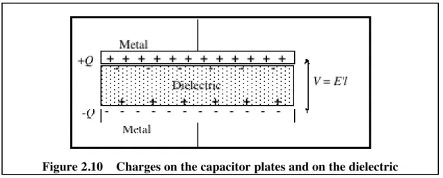
These bound surface charges are opposite in sign to the free charges, ±Q, on the metal plates (figure 2.10). They have the effect of reducing the total electric field strength within the material, and hence of reducing the voltage between the plates.
Figure 2.10 Charges on the capacitor plates and on the dielectric
Instead of specifying values of permittivity for various dielectrics, it is more meaningful to give a factor by which a dielectric will increase the capacitance above the vacuum value. This factor, which we will call relative permittivity,is defined as the ratio of the permittivity of the dielectric to the permittivity of free space:
E2: Electric potential 23
k = e
e
0 .... (2.8)
Although the term relative permittivity describes this quantity precisely, it is more commonly known as dielectric constant.
The capacitance of a parallel plate capacitor with a dielectric material between the plates is then C = ke0 Al .
For perspex, k = 2.0 and for water, k!=!80.
Energy stored in a capacitor
Since work must be done to separate charges, a charged capacitor contains stored electric potential energy:
U = 12 CV2 ... (2.9).
Note. If you are interested in seeing where this relation comes from, follow this argument. The work done in separating a charge dq when the capacitor voltage is V is
dW = Vdq \ dW = CV dV [since dq = CdV] \ dW= 0 W
Ú
CV dV= 12 0 VÚ
CV2Example. In the capacitor storage bank of the TORTUS tokamak, there is a total of 3.3 farads of capacitance at a voltage of 400 volts. The stored energy (1
2 C V
2) is a quarter of a million joules.
Use of capacitance measurements
Measurements of the capacitance of living cell membranes can be used to deduce the thickness of the membranes, since the capacitance depends inversely on the thickness.
2-8 EQUIPOTENTIALS AND ELECTRIC FIELDS
You have already seen that any conductor which is not actually carrying an current is an equipotential. But the ideas of potential and equipotential are not restricted to conductors. The potential difference between any two points (whether on conductors or not) is uniquely defined.
Potential differences between conductors can generally be measured by simply connecting a suitable voltmeter. It is much harder to measure potential differences in air, for example. Most instruments so distort the field that it bears little relationship to the situation existing before the measurement was attempted. For example, in fine weather the potential (relative to the ground) at a point 2 m above the ground is about 300 V, due to the permanent positive charge on the upper atmosphere. However if you stand up outside, the potential at your head is zero and the field lines are distorted by your presence.
Figure 2.11 Distortion of the Earth's electric field
The terrestrial electrostatic field is distorted by a person. The ground and the person together form a continuous conductor which must be an equipotential. The dotted lines represent equipotential surfaces
E2: Electric potential 24
Equipotential surfaces are in general imagined (mathematical) surfaces connecting points in vacuum, in air or other material which are at the same potential. Figure 2.12 shows the cross section of a pair of charged wires. The solid lines represent the equipotential surfaces. (This example is shown as a computed animated diagram in the video lecture.) The equipotentials of a dipole are similar to the pattern in figure 2.12.
Figure 2.12 Equipotentials between charged conducting cylinders Equipotentials and field lines
Equipotentials and field lines are closely related. Either is an adequate way of describing the state of electrification of a region. To see the relationship between them, remember that the electric field is just the negative potential gradient.
The strength of the field is measured by the closeness of the equipotentials, and the direction of the field is always at right angles to the equipotential surfaces. Equipotential diagrams resemble contour maps. In a map, the slope is represented by the closeness of the contours, and the direction of slope is perpendicular to the contours.
POST-LECTURE!
2-9 QUESTIONS
Q 2 . 2 On a fine day in open country the naturally occurring charge on the ground is -1.00 nC.m-2. Calculate the electric field and potential difference (relative to the ground) at a height of 3.00 m.
Q 2 . 3 By the time you have finished this course you should have some feeling for the order of magnitude of the potential difference involved in various situations. Can you find out the order magnitude of potential difference involved in each of the following?
1. Electrocardiography [example of answer ~ 1 mV] 2. Accelerating voltage in a colour TV set
3. Minimum detectable with tongue
4. Minimum felt as shock with two fingers of one hand
5. Minimum capable of causing fatal electric shock (across hand - foot) 6. Used in electrostatic precipitators
7. Motor car ignition
8. Generated in a solar photovoltaic cell 9. Of a wrist-watch batter
10. A piezo-electric gas lighter
11. Induced in a receiving aerial by a transmitter 10 km distant 12. Combing dry hair
13. Corrosion of galvanised iron 14. Nerve transmission
15. Power for electric trains 16. Operating the telephone system 17. In-hand calculators
E2: Electric potential 25 18 Electric welding
19 Between the mains live and neutral wires 20. Between the mains earth and neutral wires 21. To make a frog's leg twitch
22. Between ground and the atmosphere at a height of 1 km, in fine weather 23. An electric insect zapper
24. Ionisation of an alkali metal, M Æ M++ e.
Q 2 . 4 In a vacuum tube the anode is maintained at a potential of 2.5 kV relative to the cathode. The anode to cathode spacing is 0.10 mm. An electron is released from the cathode and accelerated by the electric field between anode and cathode. What is its kinetic energy on striking the anode? Express your answer
i) in symbols, ii) in joules.
Q 2 . 5 A living cell has a potential difference of 90 mV between the interior of the cell and the extra-cellular fluid. The interior is negative with respect to the extra-cellular fluid. What can you deduce about the electric double layer at the cell membrane?
Q 2 . 6 The membrane of a cell is electrically equivalent to a parallel plate capacitor of area 1.0!mm2 and thickness 1.0 µm. The relative permittivity of the membrane is 8.0. The voltage across the capacitor is 90!mV. Find:
i) the capacitance,
ii) the magnitude of the electric field in the membrane, iii) the stored electrical energy,
iv) the magnitude of the separated charge.
Q 2 . 7 The electric fish Gymnarchus niloticus maintains a formidable charge on its head and a charge equal in magnitude and opposite in sign on its tail.
Sketch the general form of equipotentials that you would expect for the fish swimming in deep water (as seen from the side view). How would the shape of the equipotentials change if the fish approached the surface of a metal ship (i.e. a very good conductor)?
Q 2 . 8 A spherical conductor is maintained at a potential of +6 V relative to an earthed conducting plane. The diagram shows the plane, the spherical conductor drawn to actual size and equipotentials drawn at 1 ! V intervals.
0 V + 6 V
i) Sketch in the field lines. About 10 lines would be suitable.
ii) By taking measurements from the diagram, evaluate the electric field magnitude and direction) at points 10 mm to the right of the sphere, 10 mm above the sphere and 10 mm to the left of the sphere [these points are indicated by small dotted circles].
E2: Electric potential 26
2 - 1 0 APPENDIX - MORE ON ELECTRIC DOUBLE LAYERS
In the lecture, the discussion of electric double layers was restricted to conducting planes. Now we consider them more generally: just two sheets of charge. As before they are uniform and parallel. But now the means of support is not specified.
First consider a single sheet of positive charge (figure 2.13).
+ E E + + + + + + +
Figure 2.13 The electric field of a single sheet of positive charge
By symmetry, the electric field will be directed away from the sheet in both directions as shown. The magnitude of the field is
E = s 2e
0
(i.e. the field lines from half the charge go to the right, the other half to the left).
Now introduce a second sheet having a surface charge density of equal magnitude and opposite sign.
Figure 2.14 Fields between and beyond two oppositely charged sheets
Beyond the two charge layers the contributions to E from the layers cancel. These are regions of zero field, and therefore equipotential regions.
Between the two layers, the contributions add, giving E = s
e