The Research of Load Balancing Technology in
Server Colony
. Gao Yan1,2, Zhang Zhibin2, and Du Weifeng3* 1
Intelligent Control and Development Center, Southwest Jiaotong University, Chengdu, China Email: [email protected]
2
School of Computer Science and Technology, Henan Polytechnic University, Jiaozuo, China Email: [email protected]
3
The School of Mathematics & Information Engineering, Jiaxing University, Jiaxing, China, 314001 Email:[email protected]
Abstract—When the network is using many servers to provide network services, it needs a load balancing technique. This article has researched load-balancing technique that is based on Address Translation (NAT) and that is direct routing. It is simple to say that load balancing is based on Address Translation that can turn the parallel network services of the different IP addresses into a virtual service that is on an IP address by the NAT method. Direct routing technology program is deployed and running on speed Ethernet or kilo-mega Ethernet; it needn’t to change the original topology. The client sends the data request; the load-balancing device is only responsible for dispatching the request, while the application server will respond back to the client. By comparing the two techniques we can draw the conclusion: Under this load balancing that is direct routing mode, the overall performance of the system does not rely on the performance of the device of load balancing performance itself, but it depends on the performance of the application server itself. It can maximize server performance.
Index Terms—load balancing, direct routing; load Coordinator, Server pool
I. INTRODUCTION
At present, no matter what in the enterprise network, campus network or WAN, the development of the portfolio of the Web services has exceeded the most optimistic estimates of the past. With the popularity and applications of Internet, even according to the optimal allocation to construct the network at that time, it is hard to meet the normal demand for services.
For example, a site will receive millions of times the access request each day, so hardware processing power will soon become a bottleneck for the server that provides large loads Web services. Simple increasing hardware performance can not really solve this problem, because a single server's performance is always limited. In particular, the network request usually occurs suddenly. When some major event occurs, the network access will dramatically increase, resulting in network bottlenecks.
In order to solve these problems, it must use many servers to provide network services and distribute network requests to these servers to share. When it
distributes network request to a lot of servers, you need to use a load balancing technique. Through the load-balancing technology it may evenly distribute network requests to each server, and finally it settles the bottleneck problem. This article has researched load-balancing technique that is based on Address Translation (NAT) and that is direct routing. By comparing the two techniques we can draw the conclusion: Under this load balancing that is direct routing mode, it can achieve good load balancing between servers.
II. LOAD BALANCING TECHNOLOGY
A. The definition of load balancing
The meanings of load balancing has two aspects: First, it distributes a large number of concurrent accessing or data stream to the equipment of many nodes to deal with them respectively, so as to reduce the time of user’s waiting for response; second, a single heavy operation is shared to do parallel processing on the equipment of many nodes. After the device of each node finishes processing, it collects the results, and then returns the results to the user. Thus the capacity of information systems processing increases significantly.
Load balancing is not the traditional sense of "equilibrium". In general, it distributes only the load of the possible congestion in one place to many locations share. If it was renamed as "load sharing", it is perhaps better understood. In this sense it is static. Correspondingly, the dynamic load balancing analyses the really-time data packets through a number of tools. It understands network data traffic conditions, and allocates rationally the tasks.
B. The Implement structure of the load-balancing technology
On the existing network structure, load-balancing provides a cheap and effective way to extend the server bandwidth and increase throughput. It strengthens network data processing capability, and increases network flexibility and availability. It is mainly to accomplish the following tasks:
(1) It solves network congestion problems, and provides the handy service. Its achievement is independent of geographical location.
(2) It provides better visit quality for users.
* Corresponding author:Du Weifeng , School of Mathematics & Information Engineering, Jiaxing University, Jiaxing, Zhejiang, China, Email:[email protected]
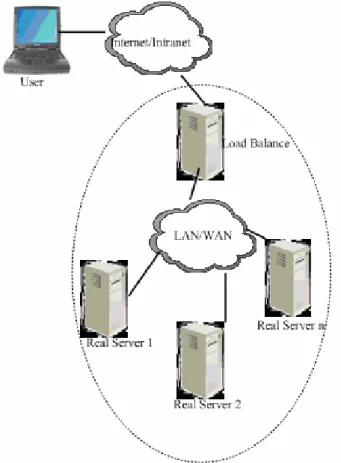
Figure 1. The solution of the load equalization colony.
(3) It improves server response speed.
(4) It improves the using efficiency of the server and other resources.
(5) It avoids a single point of failure at the key parts of the network.
III. THE MAIN TRADITIONAL METHODS OF THE ACHIEVEMENT LOAD BALANCING
A. The load balancing technology that is based on Do-main Name Service (DNS).
Load balancing between servers are using Round-Robin DNS method to achieve. NCSA (National Computer Security Association) scalable Web server is such an example. In order to improve efficiency, DNS server will cache domain name maps for some time, here , the user requests will be congregated to a host. This causes the overload.
B. Cisco's Local Director System
Cisco's Local Director System uses a virtual server to deal with the visit request of a virtual IP address. Local Director’s function is similar to an intelligent router. It directs the visit request that comes from the virtual IP address to the server that has the actual IP address. This solution is not limited to a sort of service, but the Local Director by way of this system center resource will inevitably become the system bottleneck.
C. Fast Message Insertion Technology
Fast message insertion is a technique that is based on packet filtering, Magic Router uses this technology to distribute the load. It makes a group of server "public" an IP address, without modifying any configuration of the server. Magic Router modifies the any data packet that is through it. It modifies the destination address of the data packet, and emphasizes the tolerance mistake capability and load balancing. But as a central resource, since all requests and responses go through the Magic Router, it is the system bottleneck.
D. Dynamic Packet Rewriting Technology (DPR)
Dynamic packet rewriting technology (DPR). DPR maps the IP address to the host by controlling all requests in IP layer routing. This is a distributed algorithm, which can eliminate the bottleneck problem that is caused by adopting resources centralization methods. Each host are both as a Web server and as a data packet level router. Boston University has adopted this technology in COMMONWEALTH Server. However, DPR did not propose how to provide load-balancing in the application level.
These methods are aimed at the lower network layer protocol (TCP layer, IP layer protocol) to design and implement, although its control is flexible. But each method has different degrees of deficiencies. The distributed Web server system that truly accords with network application requirements should be the dynamic distribution of the load from the application layer demand. At present, it commonly adopts load equalization colony to achieve the load balancing of the application server.
IV. LOAD EQUALIZATION COLONY
Load-balancing technology is the core of load equalization colony. When load equalization colony is running, normally it distributes the workload to a group back-end server through one or more front-end load balancer, thereby; it achieves the overall system high performance and high availability. This computer colony is sometimes referred to as server colony (Server Farm).
A. The solution of the load equalization colony
Load balancing aims at the network services demand of the high-flexibility and high-usability. It is based on the IP-layer and the load balancing scheduling solution of the content request distribution and a group of servers which make up of a virtual server of the achieving flexibility, high-usability network services. A group of servers connect each other by high speed LAN (Local Area Network) or the geographical distribution WAN(Wide Area Network ) with a load balancer at their front-end. Load balancer will be able to attempter seamlessly the network request to the real server, thus it makes the structure of the server colony be transparent for the client. The client’s visiting network services that the colony system provides is like visiting a high-performance, high-availability server. The client program isn’t influenced by the server colony and don’t need to do any changes. The system flexibility is achieved by transparent adding to and deleting a node in the service colony. It achieves high availability by detecting the failures of the node or service process and correctly resetting the system. Load scheduling technology can be implemented in hardware and software. In this article, it is mainly implemented in software. it is shown in Figure
1:
B. The structure of load-balanced colony
In general, load equalization colony uses two-tier structure, double major components:
(1) Load Coordinator (Load Balancer)
It is the front-end of machines of the entire colony in the outside, being responsible for sending the client's request to a group of servers to be carried out, while the customers think the service is from an IP address (we may call the virtual IP address);
(2) Server Pool (Server Pool)
It is a group of the servers that really implement the client request, including the services of WEB, MAIL, FTP, and DNS, etc;
The coordinator is the only entry point (Single Entry Point) of the server colony system. It can use IP load balancing technology, content-based request distribution technology or combination of both. In the IP load-balancing technology, it needs the server pool to have the same contents and provide the same services. When a client request arrives, the coordinator selects a server from the server pool only according to server load state and the stetted scheduling algorithm. It transmits the request to the selected server, and records this dispatch; when other message of the request reaches, it would be also transmitted to the selected servers of the front. In the distribution technology that is based on content request, the server can provide different services. When customers request arrives, the coordinator may select the server to execute the request according to the request contents. Because all operations will be completed in the kernel space of the Linux operating system, and its dispatch cost is small, it has a very high throughput.
The number of server pool nodes is variable. When the load that the whole system receives exceeds the current handling capacity of all nodes, you can increase the server in the server pool to meet the growing requests load. For most Internet services, the strong correlation between the requests does not exist; the request may be executed on different nodes in parallel, so the performance of the whole system increases linearly basically with the number of nodes of servers pool increasing.
C. Load Equalization Colony Performance Requirements
In the design, it need to consider the entire system of high-performance, high availability, scalability, manageability and high security. Colony system characteristic is that it has redundancy on both its hardware and software. The system's high availability is achieved through detecting node or service process fault and correctly resetting the system. Load equalization colony’s high availability is reflected in two aspects:
(1) Self-System High Availability
Coordinator itself can build high-availability pairs of machine system. When the host is system failure, spare machine turns into the host. When the original host is restored, it automatically switches back to the original state. At present, Front-end co-coordinator may become a single failure point of system (Single Point of Failure). In
general, coordinator itself has the higher reliability because the fewer process running on coordinator and core processes has been traversed long before, but we can not rule out the major fault such as the aging hardware, network lines and human misuse and so on. In order to avoid coordinator failure to result in disfunction of the entire system, we need to set up subordinate coordinator as the backup of the primary coordinator. Here we use a virtual coordinator Redundancy Protocol (VRRP: Virtual Router Redundancy Protocol) to build two high availability colonies of two coordinators. Virtual coordinator Redundancy Protocol (VRRP) is an option agreement; it can assign dynamically virtual coordinator responsibilities to the one of the LAN VRRP coordinator. The VRRP coordinator that controls IP address of the virtual coordinator is called as the primary coordinator, and it is responsible for transmitting data packets to those virtual IP addresses. Once the main coordinator is not available, this selection process has provided dynamic fault transfer mechanism, which allows the virtual IP address of coordinator can be used as the default first-hop coordinator of the terminal host. The advantage of using VRRP is that it has higher default path availability without each terminal host configure dynamic routing or routing discovery protocol. It encapsulates VRRP packets in IP packets to send. In the VRRP coordinator group, it selects master coordinator according to the priority. VRRP protocol priority range is 0-255. If the coordinator of the VRRP and the interface of the virtual coordinator have the same IP address, it claimed that the virtual coordinator act as the owner of the IP address in VRRP group; the owner of IP address automatically has the highest priority: 255. Usually it uses priority 0 when the owner of IP addresses who voluntarily gave up the role of main control. Configurable priority range is 1-254. It establishes the principle of the priority configuration according to the speed and cost of the link, the performance and reliability of coordinator as well as other management strategies in master coordinator elections, a high-priority virtual coordinator wins, so if there is the owner of IP addresses in the VRRP group, then it is always as master routing roles. For candidates’ coordinator of the same priority, it elects according to the order of IP address descending. VRRP also provides priority preemption strategy, if it has configured the strategy, high-priority backup coordinator will be deprived of the current low priority master coordinator to become the new master coordinator.
(2) High Availability of the Server Colony that are Managed by the Load Balancing Coordinator
Usually, we have monitoring process of the resources to monitor the health status of the server nodes on the coordinator at all times. When the server doesn’t reach for the ICMP ping or detecting its network services does not respond in the specified time, the monitoring process of the resource would inform the operating system kernel to remove or invalidate the server from the scheduler list. In this way, the new service request will not be dispatched to bad nodes. Monitoring process of the resource reports the failure to the administrator by e-mail
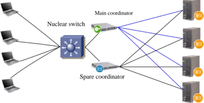
Main coordinator
Spare coordinator Nuclear switch
Figure 2. Load equalization technology based on address translation load equalization technology
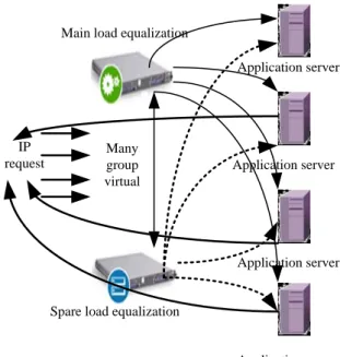
Figure 3. The data response circuit of the NAT technology realizing the load equalization
or pager. Once the monitoring processes detect the server coming back to work, it notifies the coordinator to add the server to scheduling list to dispatch. In addition, through the system management process, administrators can send commands to add the new machine ready to join the service to improve the processing performance of the system. It can also be cut out existing server from services, in order to carry out system maintenance for server. It may carry out the application server's "hot pull in-pull out”.
V. THE DYNAMIC LOAD BALANCING ALGORITHM OF THE LOAD BALANCED COLONY
Load-balancing scheduling algorithm can be divided into: the static scheduling algorithm and dynamic scheduling algorithms. The static scheduling is based on the static information of the system to achieve load scheduling balance, and the dynamic load scheduling are mainly based on the server load situation to carry out dynamic real-time scheduling. The dynamic load balancing scheduling system will get better performance. Here, it mainly introduces dynamic load balancing algorithm.
The formal description of the dynamic load balancing: The formal description of the load balancing algorithm is as follows:
There are H = (h1, h2, ..., hn) hosts in the system, there
are Ti = (ti1, ti2, ..., tim) tasks on the host hi (i = 1,2, ..., n).
it defines the task selection function Ci: Ti→ tij ∪ (Φ), it
denotes that it selects a task to carry out migration from m tasks of the host hi, if it indicated that it doesn’t need tasks migration for Φ. it defines the destination host selection function Si: tij × H → hk (hi ∈ H). Balancing
algorithm Fi that is on the host hi can be described as
follows:
(1)It carries out task selection function Ci (Ti) = tij; if tij
==Φ, it doesn’t need to migrate, the algorithm exit, otherwise it continues;
(2)It implements the host selection function Si (tij, H) =
hk, it attains destination migration nodes hk;
(3) It will migrate from tij to hk , the algorithm exit.
It can be seen from the above formal description that the dynamic load balancing involves the following four questions:
(1) When does it start balancing algorithm? It can be periodicity; it can be also event-triggered (such as when the machine is heavy).
(2) Whether or not to migrate (whether or not Ci (Ti) is Φ). Migration should accord with the condition is as following: the time that is running in the machine more than the time that migration cost + the time that is running on the remote machine. 3 times that are in formula, we are usually unable to obtain accurate values, but we estimate only them in the algorithm. This involves two key technologies: they are the estimation of the running time and the estimation communication time.
(3) Which tasks it chooses to migrate (Ci (Ti) function).
If a task remaining execution time is small, then it is not
suitable for migration, because with this task finishes that will make the system reach the imbalance.
(4) It selects the migration destination (Si (tij, H)
functions.
VI. LOAD-BALANCING TECHNOLOGY THAT IS BASED ON
ADDRESS TRANSLATION (NAT)
A. The principle of load-balancing that is based on Address Translation
It is simply to say that load balancing that is based on Address Translation that can turn the parallel network services of the different IP addresses into a virtual service that is on an IP address by the NAT method. Shown in
Figure 2:
When the client visits the network services through the Virtual IP Address (the virtual service IP address), the request packet arrives at coordinator. The coordinator selects a server from a group of real server according to connection scheduling algorithm, and rewrites the packet destination address Virtual IP Address into the selected server's address. The destination port is rewritten into the corresponding port of the selected server, and finally it sends the modified packet to the selected server. Meanwhile, the coordinator records the connection in connection Hash table. When the next packet of the connection arrives, it can gain the original selected server's address and port from the connection Hash tables, it does the same rewriting operation, and it sends packet to the original selected server. When the response packet from the real server passes the coordinator, the coordinator rewrites the source address and source port of the packet into Virtual IP Address and the corresponding port. Then it sends messages to users. We import a state machine on connection, and the different packets will make the connections in different states, and the different states have different time-out value. NAT technology
Application server
Application server
Application server Application server Main load equalization
Spare load equalization IP
request
Many group virtual
Figure 4. Load equalization of direct route technologya
implement the data response path of load balancing is shown in Figure 3:
The client sends the data request. The load-balancing device is responsible for scheduling requests, and the application server will return response to the client through the load balancing device. After application server responds to customer's request, the data pass the coordinator every time. It carries out NAT address translation, and then it returns to the client. Under this load balancing mode, the entire system's performance depends entirely on the processing capabilities of load-balancing equipment itself.
B. The Analysis of Address Translation Technology’s Characteristic
(1) System has a good manageability.
(2) It can provide effective network security for the application server;
(3) It has own network security features and NAT functionality that can save the investment of the users for firewall.
(4) Regardless of whether it is necessary to keep all conversations it need to create a queue;
(5) It needs preserving the four queues at the same time;
(6) It not only need to modify the source IP address, destination IP address and check-sum of IP packet, but also need to modify the source port, destination port and check-sum of TCP layer and so on.
(7) The response IP package must pass the coordinator, and this reduces the corresponding speed.
VII. DIRECT ROUTING (DIRECT ROUTING)TECHNOLOGY
IMPLEMENTING LOAD BALANCING
A. The working priciple of direct routing technology
Direct routing technology program was deployed and was running on speed Ethernet or kilo-mega Ethernet; it needn’t to change the original topology. The client sends the data request; the load-balancing device is only responsible for dispatching the request, while the application server will respond back to the client.
In IP-based load-scheduling technology, when an initial SYN packet of TCP connection arrives, the coordinator selects an application server and transmits message to it. After this it ensures follow-up packets is transmitted to the server through searching IP and TCP packet header address. For the UDP data packet scheduling, the coordinator also will build schedule record and set the timeout value; in the set period, data packets that come from the same address and has the same service request (IP address and port) was dispatched to the same application server. After application server responds to customer's request, the data is no longer handled through the load-balancing device, but it directly returns to the client.
Under this load balancing mode, the overall performance of the system does not rely on the performance of the device of load balancing performance itself, but it depends on the performance of the
application server itself. It can maximize server performance.
B. The dynamic load balancing algorithm that is based on task allocation list
Load balancer uses the dynamic load balancing algorithms that is based on task allocation table. This algorithm uses general centralized load balanced strategy (GCDLB). It uses the overall information to make the load balance decision, and it completes the overall load collection and the overall load balance computation by some node as the control center. It carries on the task scheduling and the load balancing.
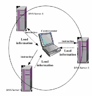
There is a control center in load coordinator, and it needs each application server to send its own load information to the control center, namely it is all to one (all-to-one) information transmission, as well as afterwards the control center sends the instruction to the application server, namely it is one to al l (one-to-all) instruction transmission. This reduces the system synchronization expenses and the network correspondence load.
Through overall centralized load balanced strategy, it can grasp the whole load information accurately, and it can carry out the whole load balance precisely, and it may record each node in detail the task migration situation. At the same time, through the establishment control center, it may manage the whole scope node and the parallel task joins and the withdrawal or because the node failure in midway causes the exceptionally termination of the parallel task and so on. Moreover, it has avoided that the computation node directly participate task assignment and the migration, and it makes the colony nodes function simplify, thus it lightens its load, and enhances the system performance. As is shown in Figure 5:
Figure 5. The achievement process of The dynamic load balancing algorithm that is based on task allocation list
Data Channel no
task desription server no computing process no Figure 6. The cell structure of task distribution list
Algorithm explanation
In dynamic load balancing algorithm that is based on task allocation list, it defines the raw data of different sources as the different data channels, and it divides tasks by data channel form. Each data channel corresponds to a structure unit of the task allocation table, and structural unit defines the computing nodes no. and the calculation process ID of the corresponding raw data solution and calculation, cell structure is shown in Figure 6; The total length of the task allocation table is its structural unit N times (N is the number of data channels).
The total real-time colony system is synchronization work under the domination of the millisecond-level precision signal that is provided by the intelligent time-unification terminals. Each colony computing nodes (DNS Server) is installed supervise control program. After the supervise control program collects completely task finish message in time-unification periodicity, immediately it sends the messages that this node work is normal to the control of the colony. If the node (DNS server) computing process is working overtime or system resources come forth unusual circumstances (such as system processor load is over weight, the motherboard temperature is overrun, the memory resource is shortages, the peripheral is failure, etc.), the monitor program immediately sends the application software work overtime or node failure messages of the node to control center. The load balancing process that resides in the
control center, after which sends “task distribution list”to each DNS server, the wait for each DNS server, it waits for the feedback messages of each DNS server completing task states. When the load-balancing software receives a node failure or the message that an application program is timeout, according to the load balancing rules, it modifies the "Task Allocation Table", and it migrates data-processing tasks of the node to other nodes.
C. The generation strategy of task allocation table
In this algorithm, it uses circular rotation means to allocate tasks for each DNS server, but before it allocates task, firstly it checks whether DNS server is available. If it isn’t available, then it allocates task for the next DNS server. In the same structure colony, each DNS server’s performance is consistent, so the difference of the tasks number between the various nodes is not more than one.
The task allocation table generation follows the following strategy: In the process of task allocation, if it is first production task allocation table, then according to the available number of DNS servers it allocates all data channels. It allocates as evenly as possible data path and keeps the allocation of marks; when there are data channel increases, it allocates only the increased data channel that is on the basis of the original allocation table, and it distributes task following the last distribution of DNS servers and processes;
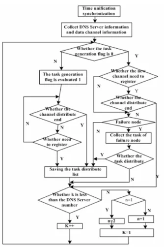
When the data channel decreases, it records the corresponding DNS server and computing process. When there is channel restoration or increase, firstly it allocates the process of this node. When the DNS server is failure, it migrates the corresponding data channel to other DNS servers. After the task allocation table is generated, it is broadcast to each DNS servers in the colony. At the same time, the control process of the DNS server writes the received raw data into shared memory, and it is for calculating daemon to read and processed. The task allocation table generation algorithm flow is shown in Figure 7:
The flow chart is shown in Figure 7. Each computing node resides two computing daemon process, k and n represents respectively the computing nodes variables and computing daemon variables. First, it allocates task for the process 1 of each node, and then the process 2 is allocated, so that the difference of the number of tasks between the various nodes is not more than one, it achieves the load even allocation in each node.
In figure 7 the flowchart can be described as follows: The first step: it waits for the arrival of the time-unification sync signal;
The second step: it receives data path registration information and the information that the DNS server load information, and it fills in the corresponding data structure;
The third step: the generation of task allocation table a) It judges whether the task generation flag is 0. (namely the task allocation table generated for the first time or a new computing nodes join)
b) If the task generation flag is 0, it can be divided into two steps to carry out the following work:
Figure 7. Production algorithm flow of task distribution list
Figure 8. Testing environment
i) It judges whether the new channel need to register. If it needn’t to register that show it has already registered before. Then it checks whether the DNS server that serve the channel is a failure node, if it isn’t failure node, it
saves the task allocation list; if it is the failure node, collecting the task in the fault node; checking whether the task that is in the fault node has allocated, if it has been allocated, it saves task allocation list; if it has not assigned, we determine whether the calculation node variable k is less than the number of DNS servers, if k is less than the number of DNS servers, then let k + 1 and return to a it judges whether the task generation flag is 0.
ii) If the channel needs to register, it shows that the channel is the first time to arrive. We must register it, and check whether the channel allocation has finished. If the channel allocation has finished, it is necessary to determine whether the calculation node variable k is less than the number of DNS servers, if the k is less than the number of the DNS server, then let k + 1 and return to a it judges whether the task generation flag is 0.
iii) In figure 7, when we judge that k is not less than the number of the DNS server , that is to that k is equal to the number of DNS servers (in this case k is larger than the number of DNS servers will not appear) ,it checks whether the calculation daemon variables n is equal to 1., if n is equal to 1, then let n is equal to 2 (let the second calculated daemon of the computing nodes to work), if n is not equal to 1, let n equal 1 (let the first calculated
daemon of the calculating node to work).Let k equal 1 (that starts to assigned tasks from the first DNS server).
c) If the task generate flag isn’t 0, set the generation flag 1. And then determine whether the channel has been allocated end, if the channel allocation has finished, it saves the task allocation table. If the channel allocation has not been finished, it checks whether the channels has registered, if the channel has been registered, it determine whether k is less than the number of DNS servers, if the k is less than the number of the DNS server, then let k + 1 and return to a it judges whether the task generation flag is 0.if k isn’t less than the number of the DNS server, it carries out iii).
D. The Analysis of the Direct Routing Technology’ Characteristic
(1) Its performance is superior, and its network throughput is high;
(2) The cost of the system construction is low, and load-balancing equipment their own building cost of high-availability is low.
(3) The network structure is simple;
(4) Merely when it needs to maintain conversation, it needs to create a queue;
(5) Even if it is maintaining conversation, it only needs to maintain a queue;
(6) When it transmits IP packets, it only needs to modify the destination MAC address, and check-sum fields;
(7) It responds to IP packets without passing load-balancing equipment, and it improves the speed accordingly.
VIII. SYSTEM TESTING
In test environment, there is a large server that assumes data acquisition and preprocessing of services network.
Figure 10 Testing environment Figure 9 Testing environment
Figure 11 Server CPU quantity to performance influence
After the data obtained is pre-processed, it is sent to the four servers of the background analysis of the behavior through the load balancing function of the server of the main coordinator. The storage system is the SAN manner, a fiber switch and a large disk array. Two mutual backup co-coordinator complete high-availability of the load balancing system, and high availability of the server colony are implemented by the management function of the load balancing colony.
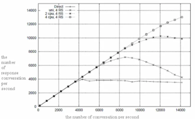
A. The contrast of two load-balancing performance of direct routing and NAT
As indicated above, we use NAT technology to do load balancing respectively for 1-4 servers. We found when the number of conversation per second is more than 4000, the system appears bottlenecks, and the response of the number of conversation gradually reduces. The number of the application server (real server referred to as RS) change for improving the overall system performance has almost no effect. Thus, the bottleneck of NAT technology lies in the conversation response speed.
As shown above, we use direct routing (DR) technology to do load balancing respectively for 1-4 servers. When per second conversation exceed 8,000, the entire system bottlenecks will appear. But the increase of the number of servers has an evident effect on the improvement of the entire system performance.
Test Conclusion: In the same environment, the performance of load balancing of the direct routing
technology is significantly higher than the load balancing of NAT technology.
B. The number of server CPU’s impact on the performance
As is shown above, with the application server (RS) increases in the number of CPU, the whole performance of the system improves in more obvious results. In four sets of CPU server environment, the number of conversation that per second respond is more than 13,000.
C. Test Conclusion
Through a series of comparison tests, in the data behavior analysis project of network users, it needs to adopt a direct routing technology to implement load balancing, while it decides the number of servers and server CPU according to the portfolio of different customers.
IX. CONCLUSION
We can draw the following conclusions through testing:
Using the server load balancing of direct routing technology has the following advantages: it has superior performance with high network throughput; system construction cost is low; construction cost of load-balancing equipment itself is low; IP packets doesn’t pass load balancing device; it improves the speed etc.
ACKNOWLEDGMENTS
This work has been supported by the National Natural Science Foundation of China (Grant No. 60875034), Henan province Natural Science Foundation (Grant No. 0611055800), Henan Province key attack project 082102210079, Henan province Science and Technology Tackle key Project (0424460013). This work was partially supported by Zhejiang province fatal project (priority subjects) key industrial project (2008C11011).
[1] Baltagi B H. Econometric analysis of panel data(third edition)New York Wiley.2005.
[2] Hsiao C. Analysis of panel data(second edition).Cambridge Cambridge University Press.
[3] Cemmeno R, Grier K.Conditional Hetemskedasticity and Cross-Sectional Dependence ineds. Contributions in Economic Analysis. Amsterdam Amsterdam Elsevier Press.2006.
[4] Depreciation: Panel evidence for the G7 and 8 Latin American Countries. April.2005.
[5] MUKHERJEE B.Optical communication networks[M]. New York: Mc-Graw-Hill,1997.
[6] MURAKAMI M,MATSUDA T. Long-haul WDM transmission using higher order fiber dispersion management[J].Lightwave Technology,2000,18(9):1197-1204.
[7] ARMITAGE J.CROCHAT O.LE B J-Y. Design of a survivable WDM photonic network[C]//Proceeding of IEEE INFOCOM’97.[S.I.]:IEEE Press,1997.
[8] NARVAEZ P,SIU K Y. Efficient algorithms for multi-path link state routing[C]//ISCOM’99[S.I]:IEEE Press,1999. [9] GOJMERAC I, ZIEGLER T, REICHEL P.Adaptive
multipath routing based on local Cemmeno R, Grier K.Conditional Hetemskedasticity and Cross-Sectional Dependence ineds. Contributions in Economic Analysis. Amsterdam Amsterdam Elsevier Press. 2006.