IQ Power
TM
Static Neutralizing System
MPS Power Supply
TABLE OF CONTENTS
1. SAFETY WARNINGS ... 1 2. DESCRIPTION ... 2 Features ...3 3. SPECIFICATIONS ... 4 4. INSTALLATION ... 5 Initial Considerations ...11Mounting the Static Neutralizing Bar ...12
Mounting the Power Supply ...13
Electrical Connections ...13
Power Supply Number (Address / Device Number) ...16
Set Up (with IQ Power Control Station) ...16
5. OPERATION ...19
Power Supply Indicators ...19
Power Supply Operators ...19
System Start-up ...19
Static Bar Operation ...20
System Operation (with IQ Power Control Station) ...20
6. MAINTENANCE ...21
Cleaning the Static Bar ...21
7. TROUBLESHOOTING ...23
8. PARTS AND ACCESSORIES...24
1. SAFETY WARNINGS
PLEASE READ INSTRUCTIONS COMPLETELY BEFORE STARTING INSTALLATION.
ALL INSTALLATION AND TROUBLESHOOTING OPERATIONS MUST BE PERFORMED BY QUALIFIED TECHNICAL PERSONEL.
This instruction manual uses symbols to identify dangerous situations as follows:
NOTE – Statements identified with a NOTE indicate precautions necessary to avoid potential equipment failure.
CAUTION – Statements identified with a CAUTION indicate potential safety hazards.
WARNING – Statements identified with a WARNING indicate potential safety serious injury hazards.
NOTE – This equipment must be correctly installed and properly maintained. Adhere to the following notes for safe installation and operation: 1. Read instruction manual before installing or operating equipment.
2. Only qualified service personnel are to perform installation and repairs.
3. All equipment must be properly grounded, including the machine frame to which the equipment is mounted.
4. Turn off or disconnect input power to power supply before connecting or disconnecting static neutralizing bars to the high voltage power supply.
5. Do not operate system in close proximity to flammable liquids.
CAUTION – This product is intended to be supplied by a Listed AC Adapter or Power Unit marked “Class 2” or “LPS” and rated output 24V 1.7A, as provided. Negative must be grounded.
CAUTION – Electrical Shock Hazard
Disconnect input power to high voltage power supply before connecting or disconnecting static neutralizing bar or performing any maintenance to the system. Avoid touching static neutralizing bar when power supply is energized.
WARNING – Fire Hazard
Do not install or operate static neutralizing bar in close proximity to any flammable liquids or solvents.
2. DESCRIPTION
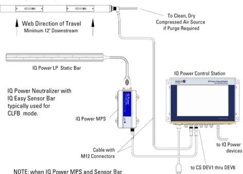
Simco-Ion’s IQ Power MPS Static Neutralizing System consists of a high voltage power supply, static neutralizing bar, and the following optional devices: control station, and static sensing bar. The MPS is typically used in conjunction with the LP bar. The IQ Power LP static bar features a low profile and plug-in style high voltage connector that is compatible with other power supplies in the IQ Power line. The IQ Power LP is a speed type static bar. The IQ Power Control Station provides the ability to both monitor and control real time system performance. The IQ Easy Static Sensor Bar enhances the Control Station’s ability to both monitor and control the static eliminating performance of the MPS.
The high voltage power supply module provides microprocessor controlled high voltage DC output to the static bar. The high voltage causes the ionizing pins on the static bar to generate positive and negative ions. The electric field from the static charge on the material being processed attracts opposite polarity ions from the static bar causing the material to be neutralized. Excess ions will either recombine in air or dissipate to ground.
The LP static neutralizing bar features current limiting at each individual ion emitting pin to minimize the risk of hazardous electrical shock if the bar is touched while in operation. This safety feature does not compromise the IQ Power system’s ability to neutralize static charges. The emitter pins are made of tungsten to extend the longevity and sharpness of the points, providing optimal performance of the static bar.
The IQ Power MPS may be powered independently with an AC adapter or as part of an IQ Power system from the Control Station. When part of an IQ Power system, a pre-terminated cable with M12 connectors is used for connection to the Control Station. These cables provide power and communication for the IQ Power MPS. For details on these cables, contact Simco-Ion customer service (800) 203-3419 (refer to Section 8, Parts and Accessories).
The Control Station is a convenient hub that provides power and communication for up to ten IQ Power or IQ Easy devices. The two-way digital communication provided by the Control Station enables monitoring and logging of system performance and allows access to enhanced features in the static neutralization system. These enhanced features include; manual control of ionization balance, Auto-Tune automatic control of ionization balance, and CLFB (Closed Loop Feed Back) providing the ultimate in static eliminator control (use of the IQ Easy Static Sensor Bar is required).
The Control Station may also be configured with a port for an Anybus® CompactCom module. This module provides interface with a wide variety of standard industrial
Features
• The IQ Power LP static neutralizing bar features a low profile.
• Static bar disconnect plug pre-installed on static bar cable for quick and easy installation.
• Ionization emitter points current limited to enhance operator safety. • Ionization emitter points of tungsten to extend operating life of emitter
points.
• Continuous mounting slot on static bar and mounting brackets for easy and flexible installation.
• Indicators on power supply display status of neutralizing system and detection of system faults.
• Connection available on power supply for remote sensing, alarm status and standby control of power supply.
• Optional control station that provides power and a communication hub for IQ Power static neutralizing systems.
• Optional static sensor bar for gathering web charge data (used in CLFB mode).
3. SPECIFICATIONS
MPS Miniature Power Supply
Input Power 24 VDC, 1A (max) , negative ground, from AC adapter or Control Station Output Voltage +/-7.5 kV
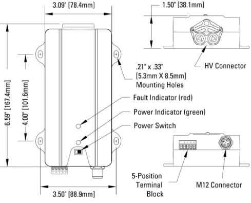
Dimensions 6.59”L x 3.09”W x 1.50”H [167.4L x 78.4 W x 38.1H mm] (not including mounting ears)
Weight 14 oz [390 g] Operating Temp 43°C [110°F] max
Enclosure Glass-fiber-reinforced Polycarbonate High Voltage Connectors 1 proprietary IQ Power plug-in outlet LP Low Profile Static Neutralizing Bar
Overall Bar Length 300-3960 mm [11.8-156”] Profile Dimensions 34W x 19H mm [1.34”W x 0.75”H] Weight 0.6 g/mm [0.5 oz/in)
Operating Temp 80°C [176°F] max
Humidity 70% RH max, no dewing permissible Enclosure Glass-fiber-reinforced Polycarbonate HV Cable Length 3m [10’] standard
Emitter Material Tungsten Emitter Spacing 30 mm [1.18”] Operating Distance 50-230 mm [2-9”]
Installation Hardware Plastic mounting brackets, metal perforated strips and stainless steel hardware (screws, washers, nuts).
AC Adapter
Type “Universal” desktop
Input Power 100-240V 50/60 Hz input (IEC 320 inlet) Part Number 4110732
Output 24V, 1.7A maximum
Dimensions 4.33”L x 2.05”W x 1.26”H [110L x 52W x 32H mm] Weight 5.3 oz [150 g]
4. INSTALLATION
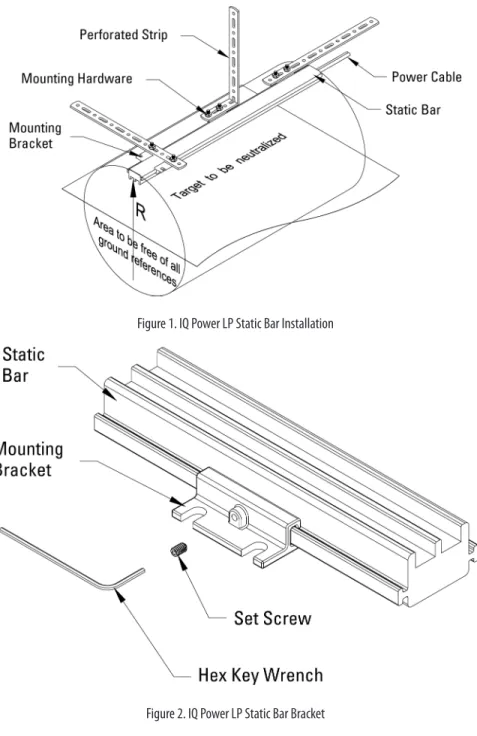
Figure 1. IQ Power LP Static Bar Installation
Figure 3. IQ Power LP High Voltage Connector
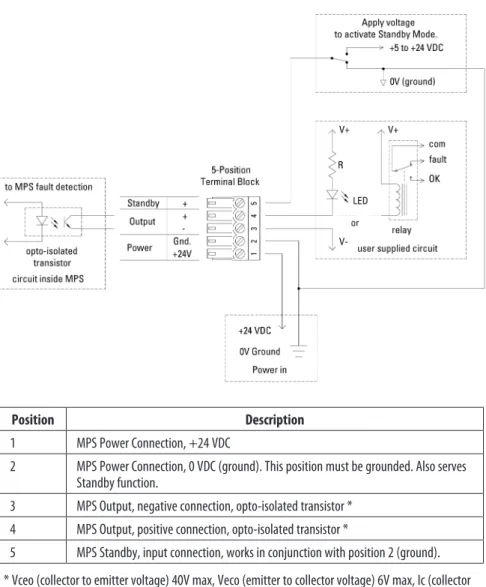
Position Description 1 MPS Power Connection, +24 VDC
2 MPS Power Connection, 0 VDC (ground). This position must be grounded. Also serves Standby function.
3 MPS Output, negative connection, opto-isolated transistor * 4 MPS Output, positive connection, opto-isolated transistor *
5 MPS Standby, input connection, works in conjunction with position 2 (ground). * Vceo (collector to emitter voltage) 40V max, Veco (emitter to collector voltage) 6V max, Ic (collector
current) 100 mA max.
Figure 9. IQ Power MPS 5-Position Terminal Block
Initial Considerations
Installation starts with mounting of the static neutralizing bar. Static bars are typically installed just ahead of where problems due to static are occurring. The power supply is installed in a convenient location within reach of the static bar high voltage cable (standard length 3m [10 ft]) and visible to the machine operator. Control station (where used) may be installed at any convenient location and
Mounting the Static Neutralizing Bar
WARNING – Fire Hazard
Do not install or operate static neutralizing bar in close proximity to any flammable liquids or solvents.
A. Determine location for mounting the static bar. The static bar will typically be located just ahead of where problems due to static are occurring. A static audit by a Simco-Ion representative can determine the best location for the static bar. B. The appropriate operating distance, “R” (see Static Bar Installation diagram) for the IQ Power static bar is in part determined by the application. IQ Power LP static bars should be mounted between 50 and 230 millimeters [2 to 9 inches] from the web and may be installed in more congested areas of the machine, however the web path should be fixed. Optimum mounting distance for high speed webs is 100 mm [4 inches]. IQ Power LP bars have an ion emitter to emitter spacing of 30 mm [1.18 inches].
IQ Power LP bars should NOT be installed or operated at distances less than the minimum distance specified. The “free area” between the static bar and web should have approximately equal height and width. There should be NO grounded metal such as an idler roller immediately behind the web on the far side from the static bar. The area behind the static bar should be as free as possible from grounded metal. See Static Bar Installation diagram. The effectiveness of any static bar is determined in part by the distance to and speed of the target. If a static bar is not performing adequately at a given distance, it may be necessary to reduce the operating distance accordingly.
C. The IQ Power LP static bar includes plastic mounting brackets, perforated metal strips and assorted hardware.
D. Slide the mounting brackets onto the “T” channel on the sides of the static bar. E. The perforated strip may be installed on the mounting bracket at right angle
to the bar or parallel to the bar. The perforated strip may be bent or twisted to suit the application and will hold its shape as installed.
F. Once the static bar is loosely installed, tighten all hardware.
G. Install set screws into the holes in the side of the mounting bracket using the provided hex key wrench. The set screws engage the “T” on the side of the bar securing it in place.
Mounting the Power Supply
A. Locate power supply at a convenient place within reach of the static bar high voltage cable (standard length 3m [10 ft]) and visible to the machine operator. Power for the AC adapter (if used) must be available.
B. Secure power supply to the mounting surface (commonly a machine frame) using M5 or M4 [#10 or #8] hardware (not supplied).
C. Locate AC adapter (if used) at a convenient, secure place within reach of the power supply.
NOTE – Do not energize the power supply until installation is complete. Ensure that all input power switches are in the OFF (0) position during installation.
Electrical Connections
A. Connect AC Adapter (if used, AC adapter is not required if the MPS is connected to a Control Station). Make sure “POWER” switch on power supply is in the “OFF” (0) position. Route low voltage wire clear of moving machine parts and protect it from abrasion. Secure using nylon wire ties (not supplied). Do not over tighten. Insert 5-position terminal block into connector on end of unit.
Connect line voltage to input side of AC adapter. The AC adapter is a universal input type that accepts line voltage from 100 to 240 VAC 50/60Hz. The AC adapter line voltage connector accepts a line cord with an IEC 320 connector (supplied). The line cord also provides electrical ground to the AC adapter. Check electrical ground integrity in the line voltage receptacle used for the AC adapter. This ground must not be defeated.
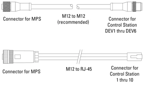
B. Connect Control Station (if used). The Control Station can supply 24 VDC power for up to ten IQ Power static eliminator power supplies. Use a pre-terminated M12 cable with straight connectors on both ends, a variety of lengths are available, see Section 8, Parts and Accessories.
When powered from the Control Station, the “Power” switch on the MPS face is not in-circuit, the MPS will energize when the Control Station power is switched on.
The M12 cable plugs into the M12 connector on the MPS power supply and into one of the six connectors numbered DEV1 thru DEV6 on the Control Station.
See diagram for Power Supply to Control Station Connections.
The cable should not be run parallel with the static bar high voltage cable. Route the cable clear of moving machine parts and protect it from abrasion.
If multiple IQ Power / IQ Easy static neutralizer devices are connected to the Control Station, each device must have a unique Power Supply Number (address / device number). This is necessary to enable reliable digital communication. The Control Station can be used to automatically address the power supplies. The default Power Supply Number for a new unit is “1”. Start the process with non-MPS devices (IQ Power BPS and IQ Easy first), connect all non-MPS devices, then finish the process with IQ Power MPS units. Plug the first power supply (only) into the Control Station and turn the Control Station on. Allow the Control Station to boot-up and begin operation. Plug the second power supply into the Control Station. The Control Station will re-address the second power supply to “2”. Plug the third power supply into the Control Station. The Control Station will re-address the third power supply to “3”. Repeat this process until all power supplies (or IQ Power / IQ Easy devices) are installed. Each power supply or device will be given a unique address (device number). C. Connect user supplied power (if used). In cases where the user does not want to
use the AC adapter but wants to supply 24 VDC power to the IQ Power MPS, user supplied 24 VDC power may be applied via the 5-position terminal block. The 5-position connector uses a Phoenix 1803604 terminal block. The
terminal block accepts 16-26 AWG solid or stranded wire with a strip length of ¼” [7mm]. To install wires into the connector, push the stripped wire fully into the square hole on the connector and tighten securely with a small flat-blade screwdriver.
To supply power through the 5-position terminal block, connect: • +24 VDC to position 1
• 0V (ground) to position 2
The return / common MUST be bonded to electrical ground.
Wired in this fashion, the “Power” switch on the MPS face is in-circuit. Power supplied in the above fashion must have adequate current available to power the MPS power supply (1A minimum). Input power should be appropriately fused for safety purposes.
See 5-Position Terminal Block diagram.
D. Connect static bar by plugging in high voltage connector on static bar cable to HV connector on power supply. Secure high voltage connector with the (2) captive screws on the sides of the connector. Do not over-tighten.
NOTE – Failure to fully seat the high voltage connectors into the power supply connectors may result in permanent damage to the bar, cable or power supply.
Secure high voltage cable from the static bar. Route the cable clear of moving machine parts and other wiring. Do not make sharp bends or “kink” the cable. Secure cable using nylon wire ties (not supplied). Do not overtighten.
NOTE – Sharp bends in the static bar cable such as kinks, routing the cable over sharp metal edges, or nicks and cuts in the cable insulation must be avoided. Stress or minor damage to the cable insulation may cause failure of the cable insulation.
E. Connect 5-position terminal block (if used). The power supply 5-position terminal block is a pluggable connector that uses a Phoenix 1803604 terminal block with screw terminals. The terminal block accepts 16-26 AWG solid or stranded wire with a strip length of ¼” [7mm]. To install wires into the connector, push the stripped wire fully into the square hole on the connector and tighten securely with a small flat-blade screwdriver.
Status Output. The terminal block provides an opto-isolated output to indicate status of the MPS power supply. The opto-isolated transistor is in conduction during normal operation or when the unit is in standby mode. The opto-isolated transistor is non-conducting in the event of a fault, input power outage or shut-down of the MPS power supply.
Standby Input. The terminal block provides an input to place the MPS power supply in Standby Mode (HV off). The input accepts a range of +5 to +24 VDC. When voltage is not applied the MPS power supply is in Run Mode. See 5-Position Terminal Block diagram.
The 5-position terminal block also provides a means of remote power in. See section “C. Connect user supplied power” for more details.
F. Connect Sensor Bar (if used). An IQ Easy Sensor Bar may be integrated into the IQ Power system to provide feedback on static eliminating performance and is used for the CLFB (Closed Loop Feed Back) static eliminating mode. Standard cables are available for connecting the IQ Easy Sensor Bar to the IQ Power Control Station. These cables are available with a straight or right angle connector for the sensor bar and have an M12 straight connector for the Control Station connection.
The cable should not be run parallel with the static bar high voltage cable. Route the cable clear of moving machine parts and protect it from abrasion. Secure using nylon wire ties (not supplied). Do not over-tighten wire tie. If there is an excess of cable, do not coil it in the vicinity of the static bar high voltage cable.
Power Supply Number (Address / Device Number)
Each IQ Power MPS has an address (number) associated with it. These numbers serve to identify the power supply in digital communications with a Control Station. This address can be a number of 1 through 10 (the default is “1”).
NOTE – If multiple IQ Power / IQ Easy devices are connected to the Control Station, each static neutralizer must be given a unique address / device number.
Automatic addressing of power supplies may be achieved by connecting devices to the Control Station in the correct sequence. Start the process with non-MPS devices (IQ Power BPS and IQ Easy first), finish the process with IQ Power MPS units. Plug the first power supply (only) into the Control Station and turn the Control Station on. Allow the Control Station to boot-up and begin operation. Plug the second power supply into the Control Station. The Control Station will re-address the second power supply to “2”. Plug the third power supply into the Control Station. The Control Station will re-address the third power supply to “3”. Repeat this process until all power supplies (or IQ Power / IQ Easy devices) are installed. Each power supply or device will be given a unique address (device number).
Manual re-addressing of power supplies may be achieved through the Control Station user interface device page. It may be necessary to tap on a tab and/or the Page arrow to locate the Device Address. The device address will be found listed as “MPS Address”. Tapping the pencil icon next to the address will open a prompt for a password. The default password for set-up is “PASSWORD”. Tapping the desired number changes the device address for the device.
Set Up (with IQ Power Control Station)
A variety of information can be checked, and operating parameters set, for the IQ Power MPS power supply through the IQ Power Control Station via the device page. Tap on the device icon for the MPS and static bar to access these pages. A summary tab will appear offering important information. Tabs for the neutralizer and sensor (if installed) will also appear. Tapping on a neutralizer tab or sensor tab opens a page where operating parameters may be edited or selected. Typical parameters are listed below.
Device Name: A user editable name to identify the specific device (14 characters).
Bar Type: A fixed description for the type of bar connected to the MPS (speed)
Operation Mode: A user selectable operating mode for the static bar (Manual, Fixed, Auto-Tune, CLFB).
ion current to optimize static neutralization performance. In order to successfully invoke Auto-Tune, certain operating parameters must be defined:
– Web Speed Mode will have to be set.
– Web Speed will have to be entered by the user.
– Mounting Distance will have to be entered by the user. It is the distance between the face of the static neutralizing bar and the web, or material to be neutralized.
• CLFB - Closed Loop Feed Back. The best control of ion balance. An IQ Easy Sensor Bar must be paired with the MPS for closed loop control. The sensor bar must be downstream of the static neutralizing bar in order for CLFB to work. The sensor bar detects any voltage imbalance on the web, or material to be neutralized, then transmits this information to the static neutralizing power supply. The power supply makes incremental changes to the balance setting until downstream charges are minimized.
• Manual - Allows manual control of the ion balance. Manual mode includes voltage regulation and current monitoring found in the standard mode, plus manual control of the ion balance ratio. This mode of operation would only be selected where the web, or material to be neutralized, exhibited extreme and consistent charging of one polarity.
Bar HV - Allows turning the HV power supplies on / off (standby mode).
Ion Output - The ionization level, in percent, where Bar Calibration = 100%.
Balance - A ratio of input power supplied to the high voltage power supplies that is related to ion balance. In Fixed, Auto-Tune and CLFB modes this is a display only and non-editable. The Balance may only be user adjusted in the Manual mode.
Upstream Estimate - An on/off setting enabling estimation of voltage on the web before the static bar. The value of the upstream estimate may be adjusted by altering the Upstream Factor.
Downstream Estimate - An on/off setting enabling estimation of voltage on the web after the static bar. The value of the downstream estimate may be adjusted by altering the Downstream Factor.
Mounting Distance - A user editable dimension, the spacing between the face of the bar and web (surface being neutralized / measured). The factory default mounting distance for speed type neutralizing bars is 4” (100mm).
NOTE – This information (Mounting Distance) MUST be correct. It is used by the static neutralizing bar when in Auto-Tune mode and used by the static sensor bar for calibration. If this information is not correct, the static bar may not operate properly when in the Auto-Tune mode or the static sensor bar may report incorrect web voltages.
Web/Bar Width - A user entered dimension, the width of the web that the static bar is being used with. This value is used in charge estimation.
Web Speed Mode - Displayed with the source on control station. A user entered value, “Device” if stored in the MPS, “Global” if stored in the Control Station.
Ion Current - The ionization level in terms of microamps for both positive and negative ionization.
Up Time - The amount of time elapsed since the device was turned on.
Device Address - The Power Supply Number (address / device number) assigned to the MPS. The address may be edited, but duplicate address numbers are not permitted. The exception to this rule is static sensor bars. If a static sensor bar is given the same address number as an MPS its data will appear as a tab under the MPS and it will automatically become paired with that MPS for CLFB operation.
Device Version - The firmware revision in the device.
Device Locator Utility - Causes the indicator lights on the device to flicker for a brief time to aid in verifying location of a given device.
IQ MPS Calibration - A time stamp indicating the last time the power supply was calibrated.
Alarm Test Utility - Causes a fault output to aid in checking /troubleshooting fault sensing connections.
5. OPERATION
NOTE – Before switching on power supply; ensure units are properly grounded and static bar & sensor bar are properly installed.
Power Supply Indicators
Power: Lights (green) to indicate power is on and the IQ Power system is ready to operate.
Flashes (green) to indicate power is on and MPS is in the Standby Mode.
Fault: Lights (red) to indicate faulty condition of static bar, power supply or high voltage connections. Power will have to be turned off to clear the fault. When fault is cleared and power is restored, the fault light will remain off. Flashes (red) to indicate a communication failure with Control Station
Power Supply Operators
Power Switch: A slide switch to turn unit on and off when connected to an AC adapter or if user power is applied through the 5-position terminal block.
The power switch is bypassed when power is applied through the M12 connector (from the Control Station). In this case, the MPS will energize as soon as the Control Station is turned on.
System Start-up
A. Apply line voltage to the AC adapter or switch on the Control Station. B. Move the power supply “Power” switch to the “On” (1) position (not necessary
if using Control Station).
C. The power supply indicators will briefly self-test during which all will light. D. After the self-test, the Fault light will extinguish and the Power light will remain
lit if the system is operating correctly.
On new systems the Ion Output parameter in the Control Station interface will display low output, calibration must be performed.
NOTE – Calibration should be performed when the system is first installed and may be performed after the static bar has been cleaned and the system verified as operating correctly.
E. If the system is new; perform an initial calibration (with Control Station only). The initial calibration sets the relative nominal ion output for the system. Calibration should only be performed on IQ Power systems that are new or just
During calibration the target to be neutralized (web, film, etc.) may remain in place, but MUST NOT BE MOVING. If the web is moving past the static bar (e.g. the machine is in operation) the calibration may be faulty.
The system should be “on”. Access the IQ MPS Calibrate parameter on the Control Station user interface device page. It may be necessary to tap on a tab and/or the Page arrow to locate the Calibrate parameter. Tapping the pencil icon next to Calibrate will open a prompt for a password. The default password for set-up is “PASSWORD”. Follow the directions on the Control Station to initiate the calibration sequence and set the relative nominal ion output for the system.
During calibration the system output will be cycled and the indicator lights on the MPS will flash. At completion of calibration the Power light will flicker. The indicated ion output at the Control Station will be high (90-100%). The calibration sequence takes approximately five seconds.
The calibration data is stored in non-volatile memory in the MPS and is used on subsequent power ups.
Static Bar Operation
A. Operation normally requires only occasional checking of the system indicators on the power supply.
B. Anticipated changes in the system indicators include a reduction of output over time. This may occur over several weeks and ultimately cause the “Clean Bar” icon to display on the Control Station. Regular maintenance will typically prevent activation of the indicator.
C. Unanticipated changes in the system indicators include activation of the Fault indicator. This would indicate faulty condition of static bar, power supply or high voltage connections. See Troubleshooting section.
System Operation (with IQ Power Control Station)
The operation of the IQ Power MPS Power Supply can be controlled through the IQ Power Control Station. In operation, a device icon appears on the Control Station Home Page. Tapping on the device icon opens a Summary page containing information about the MPS, static neutralizing bar, and static sensor bar (if paired). More detailed information and user editable parameters are available through device tabs. For information on these details see the Set Up (with IQ Power Control Station) section in this document.
6. MAINTENANCE
NOTE – Only qualified service personnel are to perform maintenance tasks.
CAUTION – Electrical Shock Hazard
Turn off power supply before cleaning bar or performing any maintenance on the system.
WARNING – Fire Hazard
Do not turn on power supply with any trace of alcohol or mineral spirits on the equipment.
The accumulation of contamination on the ionization emitter points and static bar surfaces will reduce neutralizing efficiency of the bar, therefore it is recommended that maintenance of the system be performed when the Clean Bar icon appears on the Control Station display or every three weeks, whichever comes first. Dirty environments may require more frequent cleaning. Maintenance should be performed by qualified service personnel only.
Cleaning the Static Bar
A clean brush with nylon bristles should be used to keep the ionization emitter points of the static bar clean. Periodic use of the brush will prevent deposits from accumulating on the points. The emitter points must remain sharp for optimum operation.
NOTE – Do not scrape points with any hard or sharp object that may damage points.
A. Turn off power supply.
B. Remove dirt particles deposited on the static bar with a dry, stiff nylon bristle brush.
C. Blow off the static bar with clean, dry compressed air.
D. Remove resistant coatings deposited on static bar by wiping with isopropyl alcohol or mineral spirits applied to a clean cloth. Apply isopropyl alcohol or mineral spirits to a stiff nylon bristle brush and thoroughly scrub the ionization emitter channels of the bar.
E. Blow static bar dry with clean, dry compressed air and ensure the bar is completely dry before re-applying power to the bar.
NOTE – Do not soak static bar or related components in alcohol or mineral spirits. Do not use harsh solvents such as lacquer thinner, naphtha or acetone. They will damage the bar housing and epoxy.
WARNING – Fire Hazard
Do not turn on power supply with any trace of alcohol or mineral spirits on the equipment. Allow all alcohol or mineral spirits to evaporate.
7. TROUBLESHOOTING
NOTE – Only qualified service personnel are to perform troubleshooting tasks.
CAUTION – Electrical Shock Hazard
Do not troubleshoot high voltage components with power supply energized Disconnect input power or switch power off before troubleshooting.
PROBLEM CAUSE SOLUTION
Power indicator (green) is NOT illuminated with unit connected to AC adapter.
Power not on at MPS. Turn on Power switch on MPS. Poor electrical connections. Check input power connections, both
24 VDC and line voltage. Defective AC adapter. Replace AC adapter. Power indicator
(green) is NOT illuminated with unit connected to Control Station.
Power not on at Control Station Turn on power switch near entry module. Check line voltage connections.
Poor Electrical connections. Check M12 cables and connection for damage, replace as necessary. Blown device fuse in Control Station. Reconnect MPS to different DEV
connector on Control Station. Power indicator
(green) is flashing MPS is in standby mode. Return MPS to run mode (see Electrical Connections - Standby Input)
Fault indicator (red) is illuminated.
Static bar mounted too close to
grounded metal. Separate static bar from grounded metal. Damage to high voltage connector. Replace high voltage connector. Damage to high voltage cable. Replace static bar.
Fault inside MPS. Cycle power to MPS and see if fault clears.
Return MPS to Simco-Ion for repair / replacement.
Fault indicator
(red) is flashing Communication failure with Control Station. Cycle power to MPS and Control Station to see if fault clears. Check M12 cables and connectors for damage, replace as necessary. Clean Bar icon
displayed on Control Station.
Dirt build-up on ion emitters or conductive contamination on face of bar.
Clean ion emitters and static bar. See Maintenance section for details. Process material fouling static bar ion
8. PARTS AND ACCESSORIES
Part Description Part Number MPS Power Supply (no AC adapter)
(With AC adapter, 100/120 VAC Jpn. / N. Amer. Cord) (With AC adapter, 230 VAC N. Amer. Cord) (With AC adapter, 230 VAC European Cord) (With AC adapter, 230 VAC UK Cord)
4016874 4016875 4016876 4016877 4016878 AC Adapter, IQ Power MPS 4110732 Line Cord, North American / Japan 120/100 VAC 4106272 Line Cord, North American 230 VAC 4106274 Line Cord, Continental Europe 230 VAC 4106273 Line Cord, United Kingdom 230 VAC 4107957 5-Position Connector, IQ Power MPS 5051926 M12 to M12 Cables for connecting MPS to Control
Station (straight connectors at both ends) 5 meter [16.4 foot] 10 meter [32.8 foot] 20 meter [65.6 foot] 30 meter [98.4 foot] 5051791 5051792 5051793 5051794 IQ Power HL Mounting Kit (1 bracket) 5051918 Static Bar Cleaning Brush 4670204
9. WARRANTY AND SERVICE
This product has been carefully tested at the factory and is warranted to be free from any defects in materials or workmanship. Simco-Ion will, under this warranty, repair or replace any equipment that proves, upon our examination, to have become defective within one year from the date of purchase.
The equipment being returned under warranty should be shipped by the purchaser to Simco-Ion, 2257 North Penn Road, Hatfield PA 19440, transportation prepaid and insured for its replacement cost. Prior to returning any goods for any reason, contact Simco-Ion Customer Service at (215) 822-6401 for a Return Authorization Number. This number must accompany all returned items.
This warranty does not apply when the equipment has been tampered with, misused, improperly installed, altered, has received damage through abuse, carelessness, accident, connected to improper line voltage, or has been serviced by anyone other than an authorized factory representative.
The warranty does not apply when Simco-Ion parts and equipment have been energized by other than the appropriate Simco-Ion power supply or generator, or when a Simco- Ion power supply or generator has been used to energize other than Simco-Ion parts and equipment. Simco-Ion makes no warranty, expressed or implied, nor accepts any obligation, liabilities, or responsibility in connection with the use of this product other than the repair or replacement of parts stated herein.
Simco-Ion
2257 North Penn Road Hatfield, PA 19440 (215) 822-6401 (800) 203-3419 www.simco-ion.com