APPLICATION NOTE
Ear Simulator for Telephonometry
Use of Wideband Ear Simulator Type 4195
Wideband Ear Simulator Type 4195 has been designed to match the ear simulators in Head and Torso Simulator Type 4128-C for measurements on telephone handsets. Type 4195, therefore, provides a very realistic acoustical load to the telephone handset being tested and easily shows acoustic differences between handsets as they appear in real use. This feature is vital when designing telephone handsets optimised for improved sound quality.
Features
• Conforms to ITU-T P.51 Type 3.2 realistic acoustic load (both high- and low-leak versions)
• ½ microphone and preamplifier included
• Individually calibrated (in accordance with ITU-T P.57)
Description
Wideband Ear Simulator for Telephonometry Type 4195 supplements Ear Simulator for Telephonometry Type 4185, and conforms to the IEC 60318–1 standard.
Type 4195 offers improved performance at both the low and the high end of the frequency range (up to 8.0 kHz), making it suitable for measurements on wideband telephones. This performance is obtained using a simplified pinna simulator, which adds an ear-canal extension and a cavity to the IEC 60318–4-compliant Coupler UA-1305. The cavity has carefully controlled leakage to the exterior (opening selectable in two grades). This design has been adopted as an option to the European CTR8 Standard for ISDN handset telephones and is implemented in the new wideband recommendations within ETSI and ITU – T.
All relevant calibration data are supplied on both a calibration chart and a calibration data disk. The data are stored both in a text file format (ASCII format) suitable for import to common spreadsheets and in the (legacy) binary data format of Audio Analyzer Type 2012.
Low- and High-leak Pinna Simulators
The simplified pinna simulator of Type 4195 has two well-defined leak options from the cavity to the exterior to simulate the average real-ear loss for telephone handsets that are held either comfortably tight (low-leak pinna) or loosely (high-leak pinna) against the human ear. The two grades of leakage are obtained by using two different pinna simulators. The high-leak pinna has a controlled opening consisting of a number of holes. The low-leak pinna has two very thin precision slits.
Type 4195 was made with the anatomically shaped Type 3.3 ear simulator as a reference. The acoustic behaviour of Type 4195 is, therefore, very close to that of the anatomically shaped pinna simulator. Type 4195 measures at the Drum Reference Point (DRP). By using the individually measured frequency sensitivity responses supplied with the ear simulator, the measurements can be referred to the Ear Reference Point (ERP).
Type 4195 is recommended for measurements on supra-aural and supra-concha earphones, sealed and unsealed, and for both high and low impedance (covering practically all kinds of earphone design). It can be used in a wide frequency range, from 100 Hz to 8 kHz.
Assembly
Wideband Ear Simulator Type 4195 includes the following accessories:
• ½ Microphone Preamplifier Type 2669
• IEC 60318–4-compliant Coupler UA-1305 • Low-leak Simplified Pinna Simulator UA-1304 • High-leak Simplified Pinna Simulator UA-1448 • Soft Seal YJ-0892
• Microphone Cable AO-0419 (LEMO to LEMO) • LEMO to 7-pin Brüel & Kjær Adaptor ZG-0350
Fig. 1
Parts assembly for Wideband Ear Simulator Type 4195
The ear simulator is equipped with Soft Seal YJ-0892 to ensure a good seal between the coupler and handset surfaces, and to protect the latter from being scratched when mounting the handset for testing. Soft Seal YJ-0892 is attached to the simplified pinna simulator. The IEC 60318–4-compliant coupler is screwed into the simplified pinna simulator, and Microphone Preamplifier Type 2669 is screwed into the IEC 60318–4-compliant coupler,
which contains a ½microphone. This assembly is shown in Fig. 1.
Calibration
During manufacture the ear simulators are calibrated according to ITU – T Rec. P.57. The acoustic input impedance and the frequency sensitivity response are individually measured.
Acoustic Impedance
The acoustic impedance is defined as the acoustic input impedance of the ear simulator, as seen from the ERP. It is measured using a specially designed impedance probe containing a built-in high acoustic-impedance sound source and a calibrated probe microphone. When the acoustic-impedance probe is mounted on the ear simulator, the tip of the probe microphone is positioned exactly at the ERP. By measuring the sound pressure at the ERP from the high acoustic-impedance sound source, the acoustic input impedance of the
ear simulator can be calculated. The impedance is shown in dB relative to 1 acoustic ohm (1 Pa·s/m3). See
Fig. 2 and Fig. 3.
Fig. 2
Typical acoustic impedance for the ear simulator and the standardised ITU – T Rec. P.57: Type 3.2, low-leak curve to which Wideband Ear Simulator Type 4195 complies
Wideband Ear Simulator for Telephonometry
4195
Microphone Preamplifier 2669
IEC 60318–4 Coupler UA-1305 with 1/2" Microphone
Simplified Pinna Simulator
Soft Seal YJ-0892
120412
100 110 120 130 140 150
dB
Acoustic Impedance for Type 4195 low-leak pinna, re 1 Pa s/m3
ITU-T Rec. P.57 Typical
Fig. 3
Typical acoustic impedance for the ear simulator and the standardised ITU – T Rec. P.57: Type 3.2, high-leak curve to which Wideband Ear Simulator Type 4195 complies
Frequency Sensitivity Response
The frequency sensitivity response (also referred to as the DRP to the ERP transfer function) is defined as the modulus of the ratio of output voltage of the ear simulator to input sound pressure at the ERP, normalised to 0 dB at 1 kHz. The frequency sensitivity response is measured under open-ear conditions by mounting the artificial ear in a large plane baffle and exposing it to a plane incident wave perpendicular to the baffle. The sound pressure at the ERP is then measured using a calibrated probe microphone together with the output voltage of the ear simulator, both as a function of frequency. The frequency sensitivity response can then be calculated as the ratio of the measured output voltage of the ear simulator to the measured input sound pressure at the ERP. For practical reasons, the frequency sensitivity response is also measured under closed-ear conditions. The frequency sensitivity response is used as a correction function. Normally the open-ear response is used. The closed-ear frequency sensitivity response is primarily used for diagnostic purposes, for example, to interpret differences between handset measurements made with the two different ear simulators.
The frequency sensitivity responses for Type 4195 are shown in Fig. 4 and Fig. 5. The correction is obtained by dividing the measured data by the frequency sensitivity response (as a post-processing operation on the measurement data).
Fig. 4
Open- and closed-ear frequency sensitivity responses for Type 4195, low-leak pinna
970369/2
100 200 500 1k 2k Hz 5k 10k
100 110 120 130 140 150
dB
Acoustic Impedance for Type 4195 high-leak, re 1 Pa s/m3
ITU-T Rec. P.57 Typical
970373/2
100 200 500 1k 2k (Hz) 5k 10k
-20 -10 0 10 20 30
dB
Frequency Sensitivity Response for Type 4195 low-leak pinna, re 1 kHz
Open-ear Frequency Sensitivity Response Closed-ear Frequency Sensitivity Response
Fig. 5
Open- and closed-ear frequency sensitivity responses for Type 4195, high-leak pinna
Open-ear Frequency Sensitivity as a Correction Function
Using the open-ear frequency sensitivity response as a correction function with Type 4195, measurements made on any telephone handset can be referred to the equivalent sound pressure at ERP required to calculate loudness rating or to check results against specifications, based on measurements referred to ERP. When calculating loudness rating (RLR), no LE correction is required, since the leakage is already provided by the artificial ear.
Absolute Sensitivity
The absolute sensitivity at 1 kHz (in V/Pa) is defined as the ratio of the absolute output voltage of the ear simulator to input sound pressure at the ERP. The absolute sensitivity is specified on the calibration chart for both open and closed-ear conditions. The sensitivities can be verified using Sound Calibrator Type 4231 and, if using Type 4195, the supplied Calibration Adaptor DP-0939. See Fig. 6 for calibration setup.
Fig. 6
Calibration with Sound Calibrator Type 4231 – note the addition of Calibration Adaptor DP-0939
Normally the calibration level, P4231, produced by Type 4231
mounted on a ½ microphone is 94 dB SPL. But if an extra volume is
added, for instance, caused by the presence of a coupler unit or by the adaptor used for the calibration, the sound pressure produced by the calibrator will be affected.
Also, the required measurement conditions influence the calibration. When using the calibrator, the ear simulator is exposed to closed-ear conditions. Therefore, when calibrating, it is the sensitivity according to closed-ear conditions that is measured. As it is the open-ear sensitivity that is of interest, the calibration data must be transformed to refer to this situation.
The required sensitivities can therefore be found if the calibration level of the sound calibrator is corrected.
The calibration level must be corrected by a factor PV for any added volume and, in order to obtain the
open-ear sensitivity, must be corrected by a factor P(open – closed) to take into account the change in
sensitivity when going from closed-ear to open-ear conditions.
The corrected calibration level to obtain the open-ear sensitivity is then given by:
P4231, corrected (open ear) = P4231 + PV + P(open – closed)
The corrected level to obtain the closed-ear sensitivity is given by:
P4231, corrected (closed ear) = P4231 + PV
The calibration levels to obtain the open and closed-ear sensitivities are given in Table 1.
970374/2
100 200 500 1k 2k 5k 10k
-20 -10 0 10 20 30
dB
Frequency Sensitivity Response for Type 4195 high-leak pinna, re 1 kHz
Open-ear Frequency Sensitivity Response Closed-ear Frequency Sensitivity Response
Equivalent Diagrams
Electrical equivalent diagrams can be set up based on the mechanical properties of the ear simulator. This concept makes it possible to perform computer simulations that show the effect of the acoustic loading presented by the ear simulator.
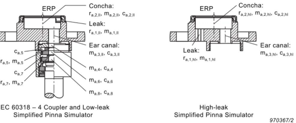
The electrical equivalent diagrams for the IEC 60318–4-compliant Coupler UA-1305 and the low- or high-leak simplified pinna simulators can be combined to give an equivalent diagram for the complete Type 4195 ear simulator. The cross-sections in Fig. 7 show the physical construction of the coupler and the low- and high-leak pinna simulators with the associated acoustical component names.
Fig. 7
Cross-section of IEC 60318–4-compliant Coupler UA-1305 fitted with low-leak simplified pinna simulator and separate high-leak simplified pinna simulator. The electrical component names refer to the separate electrical equivalent diagrams
Fig. 8 to Fig. 10 show the equivalent diagrams and associated component values for the coupler and the low- and high-leak simplified pinna simulators, respectively. The equivalent diagrams are obtained using an impedance type analogy. The circuits are seen from the acoustic side with associated component values in acoustic units. Fig. 8 Electrical equivalent diagram and associated component values for
IEC 60318 – 4-compliant Coupler UA-1305
Table 1
Actual calibration levels using Sound Calibrator Type 4231 to find the absolute open- and closed-ear sensitivities at 1 kHz
Calibration Adaptor P4231, corrected(open ear) P4231, corrected(closed ear) Type 4195
low-leak DP-0939 98.2 dB 98.0 dB
Type 4195
high-leak DP-0939 84.7 dB 85.4 dB
970367/2
Concha:
ra,2,ll, ma,2,ll, ca,2,ll
Leak:
ra,1,ll, ma,1,ll
ma,4, ca,4
ra,5, ma,5
ca,5
ERP
ra,7, ma,7
ca,7
ma,6, ca,6
ma,8, ca,8
Ear canal:
ma,3,ll, ca,3,ll
Concha:
ra,2,hl, ma,2,hl, ca,2,hl
Leak:
ra,1,hl, ma,1,hl
ERP
IEC 60318 – 4 Coupler and Low-leak Simplified Pinna Simulator
High-leak Simplified Pinna Simulator
Ear canal:
ma,3,hl, ca,3,hl
970370/2 ca,8 ca,6 ma,8 ma,7 ra,7 ca,7 ca,4 ma,6 ma,4 ma,5 ra,5 ca,5
Pa × s
m3
ra,5 = 50.6 × 10⁶
Pa × s
m3
ra,7 = 31.1 × 10⁶
ma,4 = 78.8
kg m4 kg m4 kg m4
ma,5 = 9.4 × 10³
ma,6 = 132.3
kg
m4
ma,7 = 983.8
kg
m4
ma,8 = 153.5
ca,4 = 0.9 × 10⁻¹²
N
m5
N
m5
ca,5 = 1.9 × 10⁻¹²
N
m5
ca,6 = 1.5 × 10⁻¹²
N
m5
ca,7 = 2.1 × 10⁻¹²
N
m5
ca,8 = 2.1 × 10⁻¹²
IEC 60318 – 4 Coupler: To low-leak or
high-leak Simplified Pinna
Fig. 9
Electrical equivalent diagram and
associated component values for the Low-leak Simplified Pinna Simulator UA-1304 Fig. 10 Electrical equivalent diagram and associated component values for the High-leak Simplified Pinna Simulator UA-1448
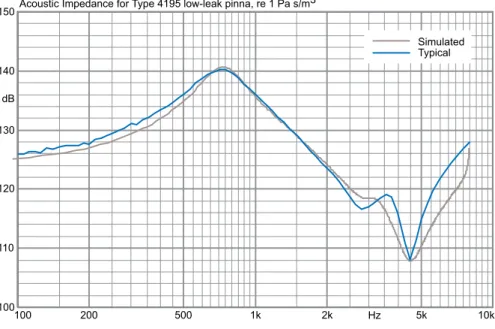
Fig. 11 and Fig. 12 show the simulated acoustic impedances of the Type 4195 with low- and high-leak simulators, respectively, based on the electrical models. Although the equivalent diagrams are based on the mechanical properties of the ear simulator, they constitute a compromise between complexity (good simulation of reality) and simplicity (poorer simulation of reality). As a consequence, some of the component values have been adapted to give the best simulation of the acoustic impedance.
Fig. 11
Simulated acoustic impedance for Low-leak Simplified Pinna Simulator UA-1304, compared to typical measured impedance curve 970371/2 ca,3,ll ma,3,ll ma,2,ll ma,1,ll ra,2,ll ca,2,ll Input (acoustic impedance) To IEC 60318 – 4
Coupler
ra,1,ll
Pa × s
m3
Pa × s
m3
ra,1,ll = 1.7 × 10⁶
ra,2,ll = 250 × 103
ma,1,ll = 982.2
kg m4 kg m4 kg m4
ma,2,ll = 38.5
ma,3,ll = 271.6
ca,2,ll = 32.5 × 10⁻¹² N
m5
N
m5
ca,3,ll = 3.1 × 10⁻¹²
Type 4195 low-leak:
ca,3,hl ma,3,hl ma,2,hl ra,2,hl ca,2,hl ma,1,hl Input (acoustic impedance) ra,1,hl
Pa × s
m3
Pa × s
m3
ra,1,hl = 280 × 103
ra,2,hl = 300 × 103
ma,1,hl= 250
kg m4 kg m4 kg m4
ma,2,hl= 45.9
ma,3,hl= 271.6
ca,2,hl = 25 × 10-12
N
m5
N
m5
ca,3,hl = 3.1 × 10⁻¹²
970372/2
Type 4195 high-leak:
To IEC 60318 – 4
Coupler
970389/2
100 200 500 1k 2k Hz 5k 10k
100 110 120 130 140 150 dB
Acoustic Impedance for Type 4195 low-leak pinna, re 1 Pa s/m3
Simulated Typical
Fig. 12
Simulated acoustic impedance for High-leak Simplified Pinna Simulator UA-1448, compared to typical measured impedance curve
970390/2
100 200 500 1k 2k Hz 5k 10k
100 110 120 130 140 150
dB
Acoustic Impedance for Type 4195 high-leak pinna, re 1 Pa s/m3
Simulated Typical
Specifications
Compliance with Standards
General Specifications STANDARDS
Acoustic performance according to ITU–T Recommendation P.57 section 5.3.2, Type 3.2
DIMENSIONS Height: 126 mm (5)
Max. Diameter: 60 mm (2.4)
WEIGHT (WITHOUT PREAMPLIFIER TYPE 2669)
107 g (3.8 oz.)
Environmental Calibration Conditions STATIC PRESSURE
101.3 ±3.0 kPa
TEMPERATURE
23 ±3C (73.4 ±5.4F)
RELATIVE HUMIDITY
60 ±20% ,
CE-mark indicates compliance with: EMC Directive and Low Voltage Directive.
C-Tick mark indicates compliance with the EMC requirements of Australia and New Zealand
Safety EN/IEC 61010–1: Safety requirements for electrical equipment for measurement, control and laboratory use.
UL 61010B–1: Standard for Safety – Electrical measuring and test equipment
EMC Emission
EN/IEC 61000–6–3: Generic emission standard for residential, commercial and light industrial environments. CISPR 22: Radio disturbance characteristics of information technology equipment. Class B Limits.
FCC Rules, Part 15: Complies with the limits for a Class B digital device.
EMC Immunity
EN/IEC61000–6–1: Generic standards – Immunity for residential, commercial and light industrial environments. EN/IEC 61326: Electrical equipment for measurement, control and laboratory use – EMC requirements.
Note: The above is only guaranteed using accessories listed in this Product Data sheet.
Temperature
IEC 60068–2–1 & IEC 60068–2–2: Environmental Testing. Cold and Dry Heat. Operating Temperature: –5 to +40C (41 to 104F)
Storage Temperature: –25 to +70C (–13 to +158F)
Humidity IEC 60068–2–78: Damp Heat: 90% RH (non-condensing at 40C (104F))
Mechanical
Non-operating:
IEC 60068–2–6: Vibration: 0.3 mm, 20 m/s2, 10–500 Hz IEC 60068–2–27: Shock: 1000 m/s2
HEADQUARTERS: Brüel & Kjær Sound & Vibration Measurement A/S · DK-2850 Nærum · Denmark
ËB
O-052
0---s
Î
B
O
05
20
–
1
1
2012-08