Strojniški vestnik - Journal of Mechanical Engineering 53(2007)10, 605-620 U DK -UD C 620.178.3
Izvirni znanstveni članek - Original scientific paper (1.01)
Vrednotenje termomehansko obremenjenih izdelkov z
deformacijskim pristopom
Evaluating Thermo-Mechanically Loaded Components Using a Strain-Life
Approach
Uroš Rosa - Marko Nagode - Matija Fajdiga (Fakulteta za strojništvo, Ljubljana)
Deformacijski pristop sodi med najbolj uveljavljene metode vrednotenja izdelkov, izpostavljenih utrujanju. Za njegovo uporabo p ri termomehanskih obremenilnih stanjih in modeliranje lokalnih temperaturno-napetostno-deformacijskih stanj je uporabljen napetostno nadzorovan reološki model vzmet - drsnik s Prandtlovim operatorjem, ki omogoča modeliranje elastoplastičnih materialnih lastnosti. Postopek
je razširjen za uporabo na zahtevnih izdelkih v kombinaciji z metodo končnih elementov (MKE). Predstavljeni
postopek vrednotenja se uvršča med deljene postopke, pri katerih se ločeno določi napetostno-deformacijska stanja in ločeno izračuna poškodba. Za izračun j e bil razvit program za izračun poškodbe (PIP), ki ima možnost uvoza rezultatov, pridobljenih z linearno ali nelinearno MKE analizo. Kritična mesta so določena z uporabo deformacijskih zdržljivostnih krivulj in Skeltonovega energijskega postopka. Materialni podatki so za neizmerjene temperature interpolirani z linearno ali odsekoma kubično Hermit-ovo metodo. Uporaba razvitega modela j e prikazana na primeru dveh standardiziranih oblik preizkušancev za deformacijsko nadzorovane preizkuse pri nespremenljivem temperaturnem polju in za kombinacijo naključnega poteka temperaturne in mehanske obremenitve. Raziskana je tudi temperaturna odvisnost parametra Kp, ki je uporabljen v Neuberjevi formuli za oceno elastoplastičnih napetostno-deformacijskih stanj iz rezultatov linearne MKE analize. Predstavljen postopek omogoča računsko hitro vrednotenje izdelkov, obremenjenih z naključno kombinacijo temperaturne in mehanske obremenitve.
© 2007 Strojniški vestnik. Vse pravice pridržane.
(Ključne besede: termomehansko utrujanje, poškodba, deformacijski postopki vrednotenja, metode končnih elementov)
The strain-life approach is one o f the most commonly used methods fo r evaluating componentfatigue. In its application fo r thermo-mechanically load states and fo r modelling local temperature stress-strain states, we use a stress-controlled rheological spring-slider model with an operator o f the Prandtl type, which makes it possible to model the elasto-plastic material properties. The approach is used to evaluate complex components in combination with the finite-element method (FEM). The described evaluation approach is classified as one o f the non-unified procedures, where we can determine separately the stress- strain states and separately calculate the damage. For the damage calculation a Damage Calculation Program (DCP) was developed. It has the possibility to import the results acquired by linear or nonlinear FEM analysis. The critical areas are determined by using a deformation endurance curve and the Skelton approach. The material data on non-measured temperatures is interpolated with the linear or cubic Hermite method. The application o f the developed model is shown on two standàrd-shaped test specimens fo r deformation control tests in a constant temperature field and fo r a combination o f the random temperature history and the mechanical load. The temperature dependence o f the Kp parameter used in the Neuber formula fo r estimating the elasto-plastic stress-strain states from thè results o f the linear FEM analysis is also included in the research. The described procedure enables a fa st numerical validation with a random combination o f temperature and mechanical load.
© 2007 Journal o f M echanical Engineering. All rights reserved.
0 UVOD
V av to m o b ilu je v rsta te rm o m e h a n sk o obremenjenih delov, to so glava in blok motorja, nosilci motorja, zavore ter celotni izpušni sistem. Vedno večje zahteve po zdržljivosti izdelkov in krajših razvojnih časih so privedle do velikega n a p re d k a m e to d n a p o v e d o v a n ja z d rž ljiv o s ti termomehansko obremenjenih izdelkov.
Za uspešno napoved dobe trajanja je treba upoštevati ustrezen materialni model s parametri, pridobljenimi s testiranji, m odeliranje napetostno- d e fo rm a c ijs k ih stan j m e d c ik lič n im obrem enjevanjem , večosnost, m odel kopičenja poškodb ter preizkušanje izdelkov za ovrednotenje soodvisnost med simulacijami in meritvami.
Za obratovalne razm ere, kjer so prisotna zapletena napetostno-deformacijska stanja je v prvi v rsti pom em bna izb ira p ra v iln e g a k rite rija za vred n o ten je v ečosnega u tru jan ja. T renutno so najbolj razširjeni naslednji postopki:
• izračun prim erjalne napetosti ali deform acije ([1] do [3]) v vsakem vozlišču m odela končnih elementov,
• uporaba napetostnih ali deformacijskih invariant [3], • m etoda kritične prerezne ravnine (prva sta jo
predlagala Brown in M iller ter kasneje dodelali m nogi raziskovalci (Socie, Fatem i - Socie, Papadopoulous,... - [4], [1] in [3])), ki upošteva v vsakem vozlišču najbolj kritično ravnino za ocenitev dobe trajanja in
• energijski postopek ([5] in [14]), ki upošteva sproščeno energijo med cikličnim obremenjevanjem.
Poleg zgornje delitve se lahko postopki delijo tudi glede na področje uporabe in zahteve analize. Zgodovinsko je bila prva delitev med “visokocikličnim” (VCU) in “malocikličnim” (MCU) utrujanjem. Na področju VCU je bilo najodmevnejše pionirsko delo W öhlerja z razvojem napetostnega p risto p a. N a področju MCU pa v šestdesetih letih dvajsetega stoletja p rispevek M ansona in C offina z u v eljav itv ijo deformacijskega pristopa. Tovrstna delitev je pogosta tudi dandanes zaradi pretežnih elastičnih deformacij pri utrujanju VCU ter plastičnih deformacij pri utrujanju MCU, kar je opazno pri metodi kritične prerezne ravnine [3] ali energijski m etodi [5], Pom em bno raziskovalno področje je tudi razvoj enotnega modela za utrujanje VCU in MCU, kar je na primem energijskih metod prikazano v [5] in [21].
N a m e n p ris p e v k a j e p o k a z a ti ra z v iti postopek, k ije kot razširitev m etod podanih v [9],
1 INTRODUCTION
In a car th e re are se v eral th erm o - mechanically loaded components, e.g., the engine block and head, the engine supports, the brakes and the whole exhaust system. The growing demands for longer lives and shorter development times have led to great advances in the methods for predicting the life o f thermo-mechanically loaded components.
F o r an effic ie n t life p re d ic tio n several requirements have to be fulfilled: a proper material m odel w ith m aterial p aram eters derived from testing, m odelling o f the stress-strain response during cycle loading, m ulti-axiality, a dam age accum ulation m odel, and com ponent testing to evaluate the correlation between the life prediction models and the experiments.
In operating conditions where complex stress- strain fields are present, the first challenge is to properly select the multi-axial fatigue criterion. At present the following criteria are the most widely used: • Calculation o f the equivalent stress or strain ([ 1 ]
to [3]) in each node o f the finite-element model. • The use o f stress or strain invariants [3], • The critical plane approach (initially suggested
by B row n and M iller and later m odified by several researchers, e.g., Socie, Fatemi - Socie and P apadopoulous - [4], [1] and [3]) that considers the critical plane in each selected node for the life estimation.
• The energy criterion ([5] and [14]) that takes into account the dissipated energy during cycle loading.
Besides the upper division, approaches can be divided according to their field o f usage or analyses requirements. Historically, the first division was between high-cycle (HCF) and low-cycle fatigue (LCF). W ohler pioneered the field o f HCF and the development o f the stress-life approach. In the field o f L C F M anson and C o ffin m ade su b stan tial developments with the establishment o f the strain- life approach. This differentiation is still present today, m ainly due to the tendencies for elastic deformation in HCF and inelastic deformation in LCF, as can be seen in the critical plane approach in [3] or the energy method [5]. An important field o f research concerns the developm ent o f a unified approach to LCF and HCF, as can be seen in the example o f the energy methods in [5] and [21],
[11] in [12], uporaben v kom binaciji z metodo končnih elementov (MKE) na izdelkih zahtevnih oblik. Metoda uporablja elastoplastičen materialni m odel vzm et - drsnik, ki omogoča m odeliranje napetostno-deformacijskih stanj pri spremenljivih obrem enitvah in temperaturah. V nadaljevanju je prikazan celotni postopek ter njegova overitev na dveh primerih.
1 PREDLAGANI POSTOPEK VREDNOTENJA TERMOMEHANSKEGA UTRUJANJA
1.1 Deljenje analiz
V p rim eru term o m eh an sk eg a u tru ja n ja (TM U) na izdelek hkrati delujejo spreminjajoče se m e h a n s k e o b re m e n itv e (sile , tla k itn .) in te m p e ra tu rn e o b rem en itv e zarad i se g rev an ja izdelka. Za pridobitev temperaturnih polj v izdelku, k i se uporabijo v trdnostnih analizah, je treba opraviti delitev med termičnimi oz. analizami CFD in trdnostnimi preračuni. Pri prvi skupini analiz se pridobi tem peraturna polja v izdelku za celoten o b re m e n itv e n i p o te k , ki se n a to skupaj z mehanskim i obremenitvami uporabijo v trdnostni M KE analizi.
V n ašem p rim eru za izraču n poškodbe izvedem o delitev m ed trdnostno in poškodbeno analizo. Pridobljena napetostno-deformacijska in temperaturna polja se izvozijo v razviti program za izračun poškodbe (PIP), kjer se izvedejo končni preračuni. U porabljena delitev analiz je uspešno u p orabljena skupaj s Skeltonovim energijskim kriterijem v avtomobilski industriji ([1],[7] in [8]).
Predlagan postopek vrednotenja poteka v naslednjem vrstnem redu:
1. Izračun tem peraturnih polj za celotni potek obrem en itev s prehodno term ično ali CFD analizo MKE.
2. Izraču n napetostno-deform acijskega odziva za obračalne točke obrem enitvenega poteka z M K E . A n a liz a j e la h k o lin e a r n a a li nelinearna.
3. Iz M K E je iz v o ž e n i p o te k n a p e to s ti in temperature za vsa vozlišča v razviti program za izračun poškodbe (PIP).
4. Če so napetosti pridobljene z linearno analizo, so v PIP-u napetosti v plastičnem področju ocenjene z Neubeijevo formulo.
5. V P IP -u se iz v e d e m o d e lira n je ce lo tn ih histereznih zank z reološkim modelom vzmet - drsnik [9].
methods given in [9], [11] and [12]. It is used in combination with the finite-element method (FEM) and can be applied to components with a complex shape. The procedure uses an elastoplastic spring- slider material model, which enables the modelling o f stress-strain states under variable loads and temperatures. In the sections that follow the entire process and its validation on two examples are shown.
1 THE PROPOSED PROCEDURE FOR TMF EVALUATION
1.1 Uncoupling of analysis
In the case o f thermo-mechanical fatigue (TMF) the variable m echanical loading (force, pressure, etc.) and the temperature loading are acting simultaneously on the component. In order to obtain the temperature fields that are used in stress-strain analyses the therm al or CFD analyses and the structural analyses are uncoupled. With the first group o f analyses the temperature fields for the entire load history are obtained, which are later applied in combination w ith the mechanical loadings in the structural finite-element analyses (FEA).
For the damage calculation the uncoupling between the structural and the damage analyses is perform ed too. The obtained stress-strain and temperature fields are exported to the developed Damage Calculation Program (DCP), where the final c a lc u la tio n is p erfo rm ed . T his k in d o f uncoupling is successfully applied in combination with Skelton’s energy criterion in the automotive industry ([1],[7] and [8]).
T he p ro p o se d e v a lu a tio n p ro ced u re is performed in the next steps:
1. Calculation o f the temperature fields for the load history with the transient thermal FEA or CFD analyses.
2. Calculation o f the stress-strain response for the turning points in the given load history with the FEA. The analysis can be either linear or non-linear. 3. From the FEA the .stress and temperature histories
for all the nodes are exported to the specifically developed Damage Calculation Program (DCP). 4. If the stresses have been computed w ith the
linear FEA the DCP estimates the elastoplastic stresses at the turning points with the Neuber approximate formula.
6. Štetje obremenitvenih ciklov z rainflow metodo z u p o š te v a n je m m eto d e z a p ira n ja ciklov, predstavljene v [9], in ekvivalentne temperature cikla[9].
7. Izvedena je ocena poškodbe s Smith-Watson- T o p p e r-je v im p a ra m e tro m [10] in o cen a sproščene energije.
1.2 Napetostno nadzorovan model elastoplastičnosti
6. After the stress-strain modelling the rainflow cycle counting is performed, by utilizing the cycle closure method used in [9] and the calculation of the equivalent cycle temperature [9].
7. D am age estim ation using the Smith-Watson- Topper parameter [10] and the estimation o f the dissipated energy is performed.
1.2 Stress-controlled model of elastoplasticity
M odeliranj e n apetostno-deform acij skega o d z iv a v P IP -u se iz v a ja s se rijsk o v ezan im m odelom vzm et - drsnik, k ije zmožen modeliranja k in e m a tič n e g a u trje v a n ja za iz o te rm n e in neizoterm ne primere. Ker je bil model že obširno predstavljen v [9], so v nadaljevanju podane le k o nčne enačbe. Ob neupoštevanju izotropnega utrjevanja je za vrednotenje utrujanja pogosto v u p o ra b i s ta b iliz ir a n a c ik lič n a n a p e to s tn o - deformacijska Ramberg-Osgoodova krivulja [9]:
£ = g (e ,T ) = ~~z
Modelling o f the stress-strain response in the DCP is performed with the stress-controlled serially connected spring-slider model, which is capable of m o d e llin g e la sto p la stic h ard en in g so lid s and nonlinear kinem atic hardening for isothermal or non-isothermal cases. The model was thoroughly presented in [9], which is why only the final set of equations is listed below:
/ \1/»\ T )
kjer so: T tem peratura, E(T) m odul elastičnosti,
K \ T ) k o eficien t cikličnega u trjevanja in n \ T )
eksponent cikličnega utrjevanja. Poleg zgornje enačbe se lahko uporabi katerokoli elastoplastično razm eije s kinematičnim utijevanjem.
Ob predpostavki, da so na voljo stabilizirane ciklične napetostno-deformacijske krivulje, je lahko e la s to p la s tič n a d e fo rm a c ija m o d e lira n a s Prandtlovim operatorjem. Celotna elastoplastična deformacija je lahko izražena v obliki Prandtlovega operatorja:
T, E(T), K ’(T) and n ’{T) are the temperature, the
Young modulus, the cyclic hardening coefficient, and the cyclic hardening exponent, respectively. There is no limitation, however, on using any other stress-strain relatio n that exhibits elastoplastic behaviour w ith nonlinear kinematic hardening.
Supposing that cyclically stable cyclic stress- strain curves are available, the elastoplastic strain can be modelled with an operator o f the Prandtl type. The total elastoplastic strain can be expressed in the form known as the operator o f the Prandtl type:
£(t,) = ' Z a j(T,)o-aj(t,) (2)
j= 0
za 0 < tx < t2 < •••< * ,.< ••■ , kjer sta T. = T(t) in for 0 < tx < t2 < • • • < * , < • • • , where T. = T(t) and <7 (f() člena s splošno začetno vrednostjo: ( J jt ) is the play operator with a general initial value:
o v (/,. ) = max M t,. ) - r , , min jer(t,. ) + r ,, ft-i )
P re d p o sta v im o , da na z a četk u n im am o P resu m ab ly , th ere is no re sid u a l stress zaostalih napetosti, torej velja: <7^(0) = 0 in e(0) = initially, so 0^(0) = 0 and f(0) = 0. The Prandtl 0. Prandtlove gostote a fT k) v področju j = 0 , . densities a (T k) in the range/ = 0,...,«r and /: = 0,...,«r in k = 0,...,«T:
(Tk ) = ~ ( s j+t (Tk ) - 2S j(Tk ) + (Tk )) (4)
Sl. 1. Določitev Prandtlovih gostot, napetostno nadzirano Fig. 1. Prandtl-density assessment, stress controled
napetosti r. so običajno enakomerno razporejene s sta ln o širin o ra z re d a Ar m ed 0 in n a jv e č jo pričakovano napetostjo (sl. 1).
Za pospešitev izračuna so vstopni poteki
o(t), T{t), materialni parametri in Prandtlove gostote
tabelirane s stalnim prirastkom napetosti Ar in prirastkom temperature AT. Tabelirani materialni parametri in Prandtlove gostote so izračunane le enkrat ter shranjene pred začetkom a,e modeliranja z en. (2).
1.3 Modeliranje napetosti in deformacij
P redznačena p rim erjaln a von M isesova napetost je izvožena iz rezultatov MKE analize v PIP, k je r p o te k a m o d e lira n je n a p e to stn o - deformacijskega odziva z napetostno nadziranim m odelom vzm et - d rsnik. N ap e to sti so lahko pridobljene z linearno ali nelinearno MKE analizo. V primeru slednje morata za pridobitev ustreznih rezultatov biti uporabljena enaka materialna modela v programu MKE in PIP-u. Zaradi omejitev modela vzm et - drsnik lahko trenutno uporabljam o le elastoplastične modele s kinematičnim utijevanjem.
Z a d o se g o ra č u n sk o h itre m eto d e v re d n o te n ja je v e lik a sk rb d an a lin e a rn o iz ra č u n a n im n a p e to stim v k o m b in a c iji s a p ro k sim a c ijsk im i e n ačb am i. M ed m n o žico
dispersed equidistantly with a constant Active yield stress class width Ar between the zero stress and the maximum expected stress (Fig. 1).
To speed up the com putation, the input histories o f o(t), T{t), the material parameters and the Prandtl densities are tabulated by setting the stress increment to Ar and choosing a temperature increment o f AT. The tabulated material parameters and the Prandtl densities are calculated only once and stored before the a,e modelling process beginning at Eq. (2).
1.3 Stress-strain modelling
The signed von Mises stress is exported from the FEA results to the DCP, where the stress- strain modelling with the spring-slider model takes place. Stresses can be computed with a non-linear or linear FEA. In the case o f non-linearly computed stresses, the same material model must be applied in both the FEA software and in the DCP program in order to obtain consistent results. Due to the limitations o f (he spring-slider model elastoplastic kinemetic hardening material models are allowed at the moment.
aproksim acijskih formul je bila izbrana pogosto uporabljena N euberjeva aproksim acijska enačba ([9] in [13]):
£= -E(T)
approximate methods from which the frequently used ([9] and [13]) Neuber approximate formula is applied:
(5),
S*/ E( T)
kjer sta imenska napetost in deformacija definirana kot S* = oJKp in e* = g(S*,T). / f je razmerje mejnih obrem enitev in g(S*,T), je stabilizirana ciklična napetostno-deformacijska krivulja, pridobljena v en.
where the nom inal stresses and strains are defined
as S* = crJKp and e* = g(S*,T). K p is the lim it
load ratio and g(S*,T) is the cyclic stress-strain curve
[13]:
curve, as defined in Eq. 1. K p is calculated using
(1). K je podan kot razmeije [13]:
K (6),
kjer je Lp sila, ki povzroči popolno plastifikacijo prereza in Lf sila, ki povzroči začetek plastifikacije v vozlišču z največjo napetostjo.
V [13] so podane naslednje vrednosti Kp: Kp = 30, Kp = 2,5 (priporočena vrednost) in i f = 1 (ne upošteva Neuberjeve formule, kar pom eni da so v h o d n e n a p e to sti n e p o sred n o u p o ra b lje n e za modeliranje napetostno-deformacijskih poti). Zaradi tem p eratu rn o odvisnih m aterialn ih lastnosti je pričakovana temperaturna odvisnost L p in Lr Za boljše ujemanje rezultatov linearne in nelinearne M K E analize je bil uveden temperaturno odvisen ifp:
K V{T):
Za primere, prikazane v nadaljevanju, je bil izračunan za najvišjo temperature na površini.
w h ere L is th e fo rc e th a t c a u se s th e fu ll p
plastification o f the analyzed cross-section and LF is the force that starts the plastification in the most stressed node.
In [13] the following values o f Kp are given:
K = 30, i f = 2.5 (recommended value) and K = 1
(the Neuber formula is not considered - the input stresses are used directly to model the stress-strain paths). Due to the temperature dependency o f the material parameters a temperature dependency is also expected for Lp and L?. For a better agreement b e tw e e n the lin e a r an d n o n -lin e a r F E A a temperature-dependent K is introduced:
Le(T)
4 CO
(7).F o r th e e x a m p le s th a t fo llo w it w as calculated for the maximum surface temperature.
1.4 Ocena poškodbe
Izb ira p rav iln e m eto d e o cen e v e lik o sti poškodbe je ključna za uspešno napoved zdržljivosti izdelka. Prikazana m etoda tem elji n a računsko hitrih in uveljavljenih postopkih. Zato je kot prvi n a č in u p o ra b lje n S m ith -W a tso n -T o p p e rje v p a ra m e te r [10]. Ta je iz ra č u n a n za v sa k obremenitveni cikel iz:
1.4 Damage estimation
An appropriate damage estimation method provides the key to an efficient life-prediction. In the proposed method, the focus is on em ploying c o m p u ta tio n a lly fa s t an d w id e ly a c c e p te d approaches. This is the reason why the well-known Smith-Watson-Topper damage parameter [10] was applied as the first damage-estimation method. It is calculated for every load cycle:
7
s
W
T (°a + )£a
E(Te) (8
)in število ciklov do začetne razpoke je pridobljeno iz naslednje enačbe:
where the num ber o f cycles to the crack initiation is obtained from:
kjer je <r’f n apetostni k o eficien t, b napetostni e k sp o n en t, e ’f d e fo rm a c ijsk i k o e fic ie n t in c deformacijski eksponent. Materialni parametri so odvisni od ekvivalentne tem perature cikla in so lin earn o ali o d se k o m a k u b ič n o H erm it-o v o interpolirani. Število ciklov do začetne razpoke je uporabljeno za izračun poškodbe z M inerjevim pravilom o linearnem kopičenju poškodbe.
K o t d ru g i p o k a z a te lj p o šk o d b e je uporabljena sproščena energija s Skeltonovim energijskim kriterijem ([14] do [16]), ki pridobiva pomembnost na področju TMU ([6] do [8] in [17]). P o g la v itn a p re d p o s ta v k a je , d a m a te ria l po za č e tn em u trje v a n ju ali m e h č a n ju do seže stabilizirano stanje pri katerem izdelek obratuje večino dobe trajanja, ter da je sproščena energija pri stabilizaciji uporabljena kot merilo določitve zdržljivosti izdelka ([6] do [8] in [14]).
Z upoštevanjem zgornje hipoteze je bilo p re d p o s ta v lje n o , d a je o b re m e n itv e n i p o te k uporabljen v stabiliziranem stanju ter izračunana sp ro ščen a e n e rg ija u p o ra b lje n a za d o lo č ite v kritičnih mest konstrukcije. V PIP-u je trenutno v uporabi poenostavljena enačba za izračun energije [17]:
Ta je up o rab ljen a za izračun energije v vsakem obremenitvenem ciklu, ki se nato linearno akumulira skozi celotni potek obremenitve:
where <f ( is the fatigue strength coefficient, b is the fatigue strength exponent, e’f is the ductility coefficient and c is the ductility exponent. The material parameters depend on the equivalent cycle temperature and can be linearly or piecewise cubic Hermite interpolated. The number o f cycles to the crack initiation is used to estimate the damage with the Miner linear damage-accumulation rule.
Skelton’s energy criterion is used ([14] to [16]) as the second dam age indicator, w hich is g a in in g c o n s id e ra b le im p o rta n c e in TM F evaluations ([6] to [8] and [17]). It is based on the assum ption th at a fter the in itial hardening or softening the material reaches a stabilized state, in which the part operates for the m ajority o f the lifetime, and that the cumulated dissipated energy during stabilization can be considered as a material constant used as a crack-initiation criterion ([6] to [8] and [14]).
In accordance with this it was considered that the load history is applied in the stabilized state and th e d is s ip a te d en erg y w as u sed fo r the id en tificatio n o f the m ost critical area o f the co m p o n en t. A t the m o m en t in the D C P the simplified equation is used [17]:
A f i p ( 1 0 ) .
It is used for calculating the dissipated energy per counted cycle. Through the calculation o f the load history in the stabilized state it is linearly accumulated:
r p =
Vrednost Wp je uporabljena za določitev kritičnih m est konstrukcije. Obe uporabljeni m etodi sta prim erni za n ak lju čn i p o tek tem p eratu rn ih in mehanskih obremenitev.
2 PRIMERI
Namen naslednjega poglavja je pokazati, da je predlagana metoda uporabna za analize zahtevnih izdelkov TMU. Za vrednotenje materialnega modela v P IP -u so re z u ltati m o d eliran ja napeto stn o - deformacijskih poti primeijani z rezultati nelinearne analize s priznanim programskim paketom ANSYS. Za dosego kratkih računskih časov je velika pozornost namenjena linearni MKE analizi v kombinaciji z N euberjevo a p ro k s im a c ijs k o form ulo. V pliv vrednosti K p na napetostno-deform acijske poti, poškodbo in sproščeno energijo je bil tudi preučen.
I AWp,
(
11
).
cycles
The value is used for the identification o f the critical areas. Both methods are suitable for a random history o f the m echanical and therm al loads.
2 EXAMPLES
2.1 Preizkušanca in material 2.1 Specimens and material
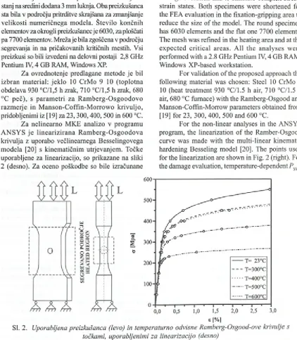
Na sliki 2 sta prikazani obliki uporabljenih standardnih preizkušancev ASTM [ 18], ki sta primerni tu d i za preizkuse pri p o v išan ih tem peraturah. Preizkušanec z okroglim prerezom premera 9 mm ter sprem enjeni 5 mm debeli ploščati preizkušanec. Slednjemu je za lažje spremljanje naraščanja poškodbe in simulacije zahtevnih napetostno-deformacijskih stanj na sredini dodana 3 mm luknja. Oba preizkušanca sta bila v področju pritrditve skrajšana za zmanjšanje velikosti num eričnega m odela. Število končnih elementov za okrogli preizkušanec je 6030, za ploščati pa 7700 elementov. Mreža je bila zgoščena v področju segrevanja in na pričakovanih kritičnih mestih. Vsi preizkusi so bili izvedeni na delovni postaji 2,8 GHz Pentium IV, 4 GB RAM, Windows XP.
Za ovrednotenje predlagane m etode je bil izbran m aterial: jek lo 10 CrM o 9 10 (toplotna obdelava 930 °C/1,5 h zrak, 710 °C/1,5 h zrak, 680 °C p eč), s param etri za R am b erg -O sg o o d o v o razm erje in M anson-C offin-M orrow o krivuljo, pridobljenimi iz [19] za 23,300,400, 500 in 600 °C.
Za nelinearno M KE analizo v program u A N SY S je lin e a riz iran a R a m b erg -O sg o o d o v a krivulja z uporabo večlineam ega Besselingovega m odela [20] s kinem atičnim utrjevanjem . Točke uporabljene za linearizacijo, so prikazane na sliki 2 (desno). Za oceno poškodbe so bile izračunane
F ig . 2. sh o w s the u se d A ST M [18] specim ens th at are also suitable for testing at elevated tem peratures. These specim ens are the round specimen o f diameter 9 mm and the modified 6 mm thick, flat specimen. In the latter a hole o f 3 mm was introduced in the centre to facilitate the damage evolution and to simulate complex stress- strain states. Both specimens were shortened for the FEA evaluation in the fixation-gripping area to reduce the size o f the model. The round specimen has 6030 elements and the flat one 7700 elements. The mesh was refined in the heating area and at the ex p ected critical areas. A ll the analyses w ere perform ed w ith a 2.8 GHz Pentium IV, 4 GB RAM, W indows XP-based workstation.
For validation o f the proposed approach the following material was chosen: Steel 10 CrMo 9 10 (heat treatment 930 °C/1.5 h air, 710 °C/1.5 h air, 680 °C furnace) with the Ramberg-Osgood and M anson-Coffm-M orrow parameters obtained from [19] for 23, 300, 400, 500 and 600 °C.
For the non-linear analyses in the ANSYS program, the linearization o f the Ramber-Osgood curve w as m ade w ith the m ulti-linear kinem atic hardening Besseling model [20]. The points used for the linearization are shown in Fig. 2 (right). For the damage evaluation, temperature-dependent PSWT
L
4
fr
% \
I
ÄS f
§3 !
9 a i
0
®
O
- a! 1
qj
V.L
J
L
3 2
!
V
Sd eft
/4 /4 /4
4>]/4
SI. 2. Uporabljena preizkušanca (levo) in temperaturno odvisne Ramberg-Osgood-ove krivulje s točkami, uporabljenimi za linearizacijo (desno)
temperaturno odvisne krivulje PSWT, pridobljene iz parametrov, podanih v [19].
2.2 Obremenitve
curves were calculated using the parameters given in [19].
2.2 Loadings
V prispevku sta predstavljena dva nadzorna p reizk u sa. Prvi je izveden pri nesprem enljivih tem p e ra tu rn ih p o ljih z naslednjim i najvišjim i tem peraturam i na segreti površini: 20, 300, 400, 500 in 600 °C (sl. 2). V teh primerih j e bil upoštevan en obremenitveni cikel z R = -1 in z obremenitvama L x = 12 kN in Z2 = 25 kN. Sili sta izbrani tako, da pri Lt v ploščatem preizkušancu napetosti presegajo ciklično mejo tečenja /J’ le v konicah napetosti okoli dodane luknje, pri sili Z, pa v večjem delu prereza.
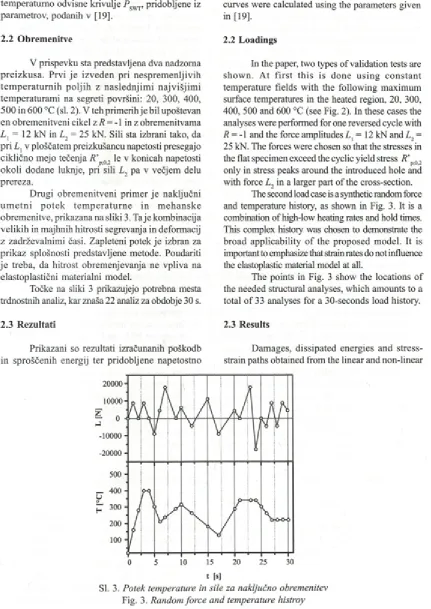
Drugi obrem enitveni prim er je naključni u m e tn i p o te k te m p e ra tu rn e in m eh an sk e obremenitve, prikazana na sliki 3. Taje kombinacija velikih in majhnih hitrosti segrevanja in deformacij z zadrževalnimi časi. Zapleteni potek je izbran za prikaz splošnosti predstavljene metode. Poudariti je treba, da hitrost obremenjevanja ne vpliva na
elastoplastični materialni model.
Točke na sliki 3 prikazujejo potrebna mesta trdnostnih analiz, kar znaša 22 analiz za obdobje 30 s.
2.3 Rezultati
Prikazani so rezultati izračunanih poškodb in sproščenih energij ter pridobljene napetostno
In the paper, two types o f validation tests are show n. A t firs t th is is done u sin g co n stan t temperature fields w ith the following maximum surface temperatures in the heated region, 20, 300, 400, 500 and 600 °C (see Fig. 2). In these cases the analyses were performed for one reversed cycle with R = -1 and the force amplitudes Z, = 12 kN and Z2 = 25 kN. The forces were chosen so that the stresses in the flat specimen exceed the cyclic yield stress R ’p02 only in stress peaks around the introduced hole and with force Z2 in a larger part o f the cross-section.
The second load case is a synthetic random force and temperature history, as shown in Fig. 3. It is a combination o f high-low heating rates and hold times. This complex history was chosen to demonstrate the broad applicability o f the proposed model. It is important to emphasize that strain rates do not influence the elastoplastic material model at all.
The points in Fig. 3 show the locations o f the needed structural analyses, which amounts to a total o f 33 analyses for a 30-seconds load history.
2.3 Results
Damages, dissipated energies and stress- strain paths obtained from the linear and non-linear
t [s ]
deformacijske poti za primere nelinearne analize in linearne v kombinacijami z različnimi K . Zaradi
povezave mehanske in od temperature odvisne specifične deformacije se najbolj poškodovano v o z liš č e p ri ra z lič n ih te m p e ra tu rn ih p o ljih s p re m in ja , četu d i so sile enake. Z a to je za p rim erjavo rezu ltato v pri obeh preizkušancih izbrano enako vozlišče za vse primere, to je najbolj poškodovano vozlišče pri lineami analizi in 20 °C. Z a okrogli preizkušanec im a izbrano vozlišče številko 7025, za ploščati pa 2288.
Napetostno-deformacijske poti so pridobljene neposredno iz predznačene von Misesove napetosti
in skupne predznačene von Misesove specifične deformacije, pridobljene iz nelinearne analize v ANSYS-U. Prikazane so tudi poti izračunane s PIP, iz rezultatov napetosti nelinearne M K E analize pa tudi tiste, pridobljene iz linearno prid o b ljenih napetosti v kombinaciji z različnimi K p.
V naslednjih slikah so uporabljene naslednje oznake:
A . N apetosti in deform acije so p ridobljene iz nelinearne M K E analize.
B. Napetosti v obračalnih točkah so pridobljene iz nelinearne M K E analize, ki so nato uporabljene v P IP u za izračun celo tn e napetostno -deformacijske poti za K p = 1.
C. Napetosti v obračalnih točkah so pridobljene iz
linearne M K E analize, ki so nato uporabljene v P IP -u za izračun celo tn e n apetostno -deformacijske poti za K = 30.
D . Napetosti v obračalnih točkah so pridobljene iz linearne M K E analize, ki so nato uporabljene v P IP -u za izra č u n celo tn e n apetostno -deformacijske poti za K p = 2,5.
E. Napetosti v obračalnih točkah so pridobljene iz linearne M K E analize, ki so nato uporabljene v P IP -u za izra č u n celo tn e n apetostno -deformacijske poti za K p( T ) (en. (8)).
2 . 3 . 1 N e l i n e a r n a M K E a n a l i z a
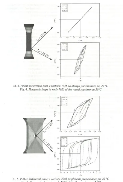
S prim erjavo rezultatov nelinearne analize
v A N S Y S -U in iz ra č u n a n ih p o ti v P IP -u je ugotovljeno, da je dobro ujem anje doseženo v obračalnih točkah (sl. 4 in 5). K lju b tem u so ra z lik e opazne iz n a sled n jih ra zlo g o v : p o ti, iz v o ž e n e iz A N S Y S - a , so iz p o s ta v lje n e lin e a riz a c iji R am berg-O sgoodove k riv u lje in prim eijalne napetosti ter specifične deformacije
so v M K E program u izračunane iz celotnega
F E A in co m b in atio n w ith d iffe re n t K ’s are p presented in this section. D ue to the different interactions between the mechanical and thermal strains, the location o f the most damaged node can move i f the temperature field changes, even i f the mechanical force remains unchanged. That is why when comparing the results the same node is chosen for all the load cases. This is the most damaged node in the linear analysis at 20 °C. For the round specimen it is numbered 7025 and for the flat specimen, 2288.
Stress-strain trajectories w ere obtained directly from the exported signed von Mises stresses and the signed total mechanical von Mises strains as provided by the non-linear solutions in the A N S Y S software. Stress-strain paths obtained by D C P from the non-linear F E A stress results, as well as those from linear F E A stresses for two distinct
K Js, are also presented.
In the figures below, the following notation is used:
A . Stresses and strains that were gained from the non-linear FEA .
B. Stresses at the turning points were taken from the non-linear FEA , and these values were then processed by D C P to produce complete stress-strain trajectories for K = 1.
C. Stresses at the turning points were taken from the linear F E A , and these values were then processed by D C P to produce complete stress-strain trajectories for K p = 30.
D . Stresses at the turning points were taken from the linear F E A , and these values were then processed by D C P to produce complete stress-strain trajectories for K = 2.5.
E. Stresses at the turning points were taken from the linear F E A , and these values were then processed by D C P to produce complete
stress-strain trajectories for K p(7 ) (see Eq. 8).
2 . 3 . 1 N o n - l i n e a r F E A
By comparing the non-linear FEA results from
A N S Y S with the stress-strain paths obtained from DCP it is clear that good agreement was reached at the turning points (Fig. 4 and 5). However, there are differences for the following reasons: Firstly, the trajectories drawn from the stress and strain values exported from A NSYS are influenced by the linearization o f the Ramberg-Osgood curves and secondly, in the FEA software, the
Sl. 4. P r i k a z h i s t e r e z n i h z a n k v v o z l i š č u 7 0 2 5 z a o k r o g l i p r e i z k u š a m o p r i 2 0 ° C
Fig. 4. H y s t e r e s i s l o o p s i n n o d e 7 0 2 5 o f t h e r o u n d s p e c i m e n a t 2 0 ° C
1 i 1 i i ' i ~l~ ' i ■ I ' i 1 i— ■ T »• i ' ~^r—■—
-6 -5 -4 -3 -2 -1 0 1 2 3 4 5 6
6 !%l
SI. 5. P r i k a z h i s t e r e z n i h z a n k v v o z l i š č u 2 2 8 8 z a p l o š č a t i p r e i z k u š a m o p r i 2 0 ° C
te n z o r ja n a p e to s ti, m e d te m ko so v P IP -u izra č u n a n e z enoosnim m odelom na tem elju predznačene prim erjalne napetosti, uvožene iz A N S Y S -a .
2 . 3 . 2 L i n e a r n a M K E a n a l i z a
complete stress and strain tensors, whereas in DCP the strain is calculated with the proposed uniaxial model from the signed equivalent von Mises stresses imported from ANSYS.
2 . 3 . 2 L i n e a r F E A
S primerjavo poti, pridobljenih z linearno analizo v kombinaciji z Neuberjevo formulo, lahko preučimo vpliv parametra K . V primeru okroglega preizkušanca pri L x ne pride do plastifikacije, v prim eru L 2 je tečenje materiala opazno. Z a vse vrednosti K p je ujemanje s histereznimi zankami iz nelinearne analize dobro. Izrazitejše razlike so opazne v ploščatem preizkušancu. V primeru L ,
vrednosti K J J ) in K p = 2,5 dasta podobne rezultate, najboljše ujemanje je doseženo s K = 30. V primeru L 2, p ri katerem je tečenje m ateriala izrazitejše,
vrednost K = 30 da izrazito nekonzervativne
p
rezultate, izračunan K p( T ) pa konzervativne. V tem
p rim e ru je n a jb o ljš e u je m a n je doseženo s priporočenim K p = 2,5.
Ugotovimo lahko, da v primeru izrazitejšega tečenja priporočena vrednost K p oz. izračunani K p( T ) da boljše ujemanje z nelinearno analizo oz.
k o n ze rv a tiv n e rezultate. Vrednost K = 30 je
u p o ra b n a v p o d ro čju m ajhn e p la s tifik a c ije materiala.
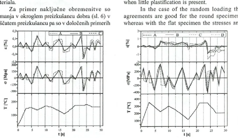
Z a p rim e r n a k lju č n e o b re m e n itv e so ujemanja v okroglem preizkušancu dobra (sl. 6) v ploščatem preizkušancu pa so v določenih primerih
B y comparing the stress-strain trajectories computed with the linear F E A and then transformed with the Neuber approximate formula, the influence o f K p can be studied. For the round specimen plastification is present only for the force L v For all constant-temperature load cases and all K p s the agreement with the non-linear F E A results is good. More pronounced differences are present in the flat specimen. In the case o f L v K J f l ) and K = 2.5 give similar results, where the best agreement is obtained with ATp = 30 . In the case o f L 2 (more plastification),
K p = 30 gives strongly non-conservative results. On the other hand, the calculated K p( T ) gives conservative results. In this case the best results are obtained with the recommended K = 2 .5 .
p
It can be concluded that in the case o f pronounced plastification the recommended value o f K and the calculated K ( T ) give the best
ag reem en t w ith the n o n -lin e a r F E A and conservative results. K = 30 can be used in the case
p
when little plastification is present.
In the case o f the random lo ading the agreements are good fo r the round specimen, whereas w ith the flat specimen the stresses and
SI. 6. N a p e t o s t n o , d e f o r m a c i j s k i i n t e m p e r a t u r n i o d z i v p r i n a k l j u č n i o b r e m e n i t v i : l e v o v v o z l i š č u 7 0 2 5 o k r o g l e g a p r e i z k u š a n c a , d e s n o v v o z l i š č u 2 2 8 8 p l o š č a t e g a p r e i z k u š a n c a
n apetosti in deformacije precenjene (sl. 6). V splošnem je ujemanje med rezultati linearnih analiz v kom binaciji z različnimi K p in nelinearno M K E
analizo dobro. Večja odstopanja so opazna v točkah k je r je izrazitejša plastifikacija, kar je v skladu s prejšnjim i ugotovitvami.
2 . 3 . 3 P o š k o d b a in s p r o š č e n a e n e r g i j a
strains are in some cases overestimated (Fig. 6). In general, the agreement o f the linear analyses in combination with the different K ’s and the
non-p
linear FEA is good. M ajor discrepancies are present where plastification is more pronounced, which is in accordance with the previous findings.
2 . 3 . 3 D a m a g e a n d d i s s i p a t e d e n e r g y
P re jš n je p o g la v je je osnova za oceno poškodbe in sproščene energije. Predpostavljeno je, da so poškodbe in sproščene energija ocenjene s P IP na osnovi n e lin e a rn ih re z u lta to v M K E “ n a jb o ljš e ” in so uporabljene kot prim erjalne vrednosti.
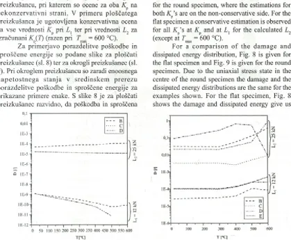
N a s lik i 7 so p rik a za n e poškodbe v odvisnosti od temperature. Ujemanje rezultatov C
i n D z p rim erjaln o B je boljše p ri okroglem preizkušancu, pri katerem so ocene za oba na n e k o n z e rv a tiv n i strani. V prim eru ploščatega preizkušanca je ugotovljena konzervativna ocena za vse vrednosti K pri L l ter pri vrednosti L 2 za izračunani K J J ) (razen pri Fmax = 600 °C).
Z a prim erjavo porazdelitve poškodbe in sproščene energije so podane slike za ploščati preizkušanec (sl. 8) ter za okrogli preizkušanec (sl. 9). Pri okroglem preizkušancu so zaradi enoosnega n a p e to s tn e g a stanja v sredinskem prerezu porazdelitve poškodbe in sproščene energije za prikazane primere enake. S slike 8 je za ploščati preizkušanec razvidno, da poškodba in sproščena
o,t
0,01 1
-i—■
—i—'—i—'—r
0 50 100 150 200 250 300 350 400 450 500 550 (
T[°q
The previous section is the basis for the damage and dissipated energy estimation. It is assumed that the damage and dissipated energy estimated with D C P based on the non-linear FEA are the “best” and considered as reference values in relation to those obtained from the linear FEA.
The temperature dependency o f the damage is shown in Fig. 7. The agreement between the results C and D with the reference results B is better for the round specimen, where the estimations for both K ’s are on the non-conservative side. For the
p
flat specimen a conservative estimation is observed for all K ’s at K and at L { for the calculated L 2
(except at Tmax = 600 °C).
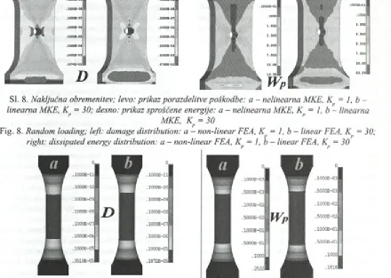
F o r a com parison o f the damage and dissipated energy distribution, Fig. 8 is given for the flat specimen and Fig. 9 is given for the round specimen. Due to the uniaxial stress state in the centre o f the round specimen the damage and the dissipated energy distributions are the same for the examples shown. For the flat specimen, Fig. 8 shows the damage and dissipated energy give us
SI. 7. P r i k a z p o š k o d b e v o d v i s n o s t i o d t e m p e r a t u r e : l e v o z a v o z l i š č e 7 0 2 5 v o k r o g l e m p r e i z k u š a n c u , d e s n o z a v o z l i š č e 2 2 8 8 v p l o š č a t e m p r e i z k u š a n c u
Sl. 8. N a k l j u č n a o b r e m e n i t e v ; l e v o : p r i k a z p o r a z d e l i t v e p o š k o d b e : a n e l i n e a r n a M K E , K p = 1 , b -l i n e a r n a M K E , K = 3 0 ; d e s n o : p r i k a z s p r o š č e n e e n e r g i j e : a - n e l i n e a r n a M K E , K = 1 , b - l i n e a r n a
M K E , K = 3 0
p
Fig. 8. R a n d o m l o a d i n g ; l e f t : d a m a g e d i s t r i b u t i o n : a — n o n - l i n e a r F E A , K p = 1 , b - l i n e a r F E A , K = 3 0 ; r i g h t : d i s s i p a t e d e n e r g y d i s t r i b u t i o n : a - n o n - l i n e a r F E A , K p = 1 , b - l i n e a r F E A , K p = 3 0
SI. 9. N a k l j u č n a o b r e m e n i t e v ; l e v o : p r i k a z p o r a z d e l i t v e p o š k o d b e : a - n e l i n e a r n a M K E , K = 1 , b — l i n e a r n a M K E , K = 3 0 ; d e s n o : p r i k a z s p r o š č e n e e n e r g i j e : a - n e l i n e a r n a M K E , K = 1 , b - l i n e a r n a
M K E , K = 3 0
P
Fig. 9. R a n d o m l o a d i n g ; l e f t : d a m a g e d i s t r i b u t i o n : a - n o n - l i n e a r F E A , K p = 1 , b - l i n e a r F E A , K p = 3 0 ; r i g h t : d i s s i p a t e d e n e r g y d i s t r i b u t i o n : a - n o n - l i n e a r F E A , K p = 1 , b - l i n e a r F E A , K p = 3 0
energija dajeta enaka kritična mesta, z večjim the same critical areas with a larger critical region kritičnim področjem okoli luknje v primem nelinearne around the hole for the non-linear case and a larger analize ter večjim kritičnim področjem okoli pritrdišča critical region around the constraint for the linear
v primem linearne analize v kombinaciji s K . F E A in combination with K .
2 . 3 . 4 R a č u n s k i č a s i 2 . 3 . 4 C o m p u t a t i o n t i m e s
Pri vrednotenju izdelkov, izpostavljenim u trujanju, je pomemben d ejavnik za določitev u p o ra b n o s ti m etode tu d i raču n ski čas. Čas računanja je bil izmeijen na ploščatem preizkušancu za naključn o obrem enitev podano na sliki 3. Linearna M K E analiza je trajala 200 s, nelinearna pa 2260 s. Za izračun poškodbe je bilo potrebno 7 s za oba primera. PIP pred oceno poškodbe izvede izračun Prandtlovih gostot, k i je neodvisen od
šte v ila obračalnih točk, zato se čas računanja
poškodbe z večanjem števila obračalnih točk ne povečuje linearno.
3 SKLEP
V prispevku je prikazan postopek, ki je razširitev metod podanih v [9], [11] in [12] na večo sno n apetostno-deform acijsko stanje in p o n u ja rešitev za vrednotenje termomehansko o b re m e n je n ih iz d e lk o v v prim eru , ko lahko zanemarimo ciklično utrjevanje oz. mehčanje in lezenje. Postopek deli termične oz. analize C FD , trdnostne analize in oceno poškodbe. Poudarek je b il na računsko h itrih metodah, zato so b ile raziskave usmerjene v uporabo linearnih M K E a n a liz v k o m b in a c iji z a p ro k s im a c ijs k im i enačbami. Ugotovljeno je bilo, da vrednost K p
pomembno vpliva na ujemanje rezultatov linearne in nelinearne M K E analize ter oceno poškodbe. Z a ta namen je bil uveden temperaturno odvisni
K ( T ) . L in e a rn e a n a liz e v k o m b in a c iji z
aproksimacijskimi enačbami in PIP-om so lahko uporabljene le ob pravilni izbiri K p in manjšem tečenju materiala. Dodatne raziskave vrednosti K p
bodo izvedne za povečanje uporabnosti približnih enačb, ki občutno znižajo računske čase pri dolgih potekih obremenitev.
time is not increased linearly with the increasing number o f turning points.
3 C O N C LU S IO N
This paper describes an extension o f the methods given in [9], [11] and [12] to a multiaxial stress-strain state and gives a solution for evaluating thermo-mechanically loaded components in the case when cyclic hardening or softening and creep can be neglected. The approach uncouples thermal calculations, stress-strain calculations and damage or dissipated energy estimations. The main focus was put on fast computational methods, which is why the research was done with the linear F E A in combination with approximate formulas. It has been observed that the K p value strongly influences the
agreement between the linear and non-linear FEA results and the damage estimation. For this reason the temperature dependent K p( T ) was introduced. The linear F E A in combination with approximate formulas and the DCP can only be used with the correct K p and a small amount o f plastification.
Further research regarding the K value w ill be carried out in order to broaden the applicability o f the approximate formulas, which substantially reduce the computation time for long load histories.
4 L IT E R A T U R A 4 R EFERENCE
[1] X . Chen, S. Xu, D. Huang (1999) A critical plane-strain energy density criterion for multiaxial low-cycle fatigue under non-proportional loading, F a t i g u e F r a c t . E n g n g M a t e r . S t r u c t . , 22(1999), pp. 679-686. [2] B. Li, L. Reis, M . de Freitas (2006) Simultaion o f cyclic stress/strain evolutions for multiaxial fatigue
life prediction, I n t . J . F a t i g u e , 28(2006), pp. 451-458.
[3] B.R . You, S.B. Lee (1996) A critical review on multiaxial fatigue assessments o f metals, I n t. J . F a t i g u e ,
18(1996), pp. 235-244.
[4] I.V . Papadopoulos, R Đavoli, C Gorla, M . Filippini, A . Bernasconi (1997) A comparative study of multiaxial high-cycle fatigue for metals, I n t. J . F a t i g u e , 19(1997), pp. 219-235.
[5] E. Macha, C .M . Sonsino (1999) Energy criteria ò f multiaxial fatigue failure. F a t i g u e F r a c t . E n g n g M a t e r . S t r u c t . , 22(1999), pp. 1053-1070.
[6] A . Constantinescu, E. Charkaluk, G. Lederer, L. Verger (1 9 9 9 ) A computational approach to thermomecahnical fatigue, I n t . J . F a t i g u e , 26(1999), p.p. 805-818.
[7] E. Charklauk, A . Bignonnet, A. Constantinescu, K. Dang Van (2002) Fatigue design o f structures under thermomechanical loadings, F a t i g u e F r a c t . E n g n g M a t e r . S t r u c . , 25(2002), pp. 1199-1206. [8] J.J. Thomas, L. Verger, A. Bignonnet, E. Charkaluk (2003) Thermomechanical design in the automotive
industry, F a t i g u e F r a c t . E n g n g M a t e r . S t r u c t . , 27(2003), pp. 887-895.
[9] M . Nagode, F. Zingsheim (2004) A n online algorithm for temperature influenced fatigue life estimation: strain-life approach, I n t . J . F a t i g u e , 26(2004), pp. 155-161.
[ 10] K .N . Smith, P. Watson, T.H. Topper ( 1970) A stress-strain function for the fatigue o f metals, J . M a t e r . ,
[11] M . Nagode, M . Hack (2004) A n online algorithm for temperature influenced fatigue life estimation: stress-life approach, I n t . J . F a t i g u e , 26(2004), pp. 163-171.
[1 2 ] M . Nagode, M . Fajdiga (2 0 0 6 ) Temperature-stress-strain trajectory modeling during thermo mechanical fatigue, F a t i g u e F r a c t . E n g n g M a t e r S t r u c t . ,29(2006), pp. 175-182.
[13] L M S D urability Technologies G m bH (20 0 0 ) L M S F a l a n c s T h e o r y M a n u a l V e r s i o n 2 . 9 , L M S Durability Technologies Gm bH
[14] R.P. Skelton (1991) Energy criterion for high temperature low cycle fatigue failure, M a t e r . S c i . T e c h .,
7(1991), pp. 427-39.
[15] R.P. Skelton, T. Vilhelmsen, G .A . Webster (1998) Energy criteria and cumulative damage during fatigue crack growth, I n t . J . F a t i g u e , 20(1998), pp. 641-649.
[16] R.P. Skelton (2004) Hysteresis, yield and energy dissipation during thermo-mechanical fatigue o f a ferritic steel, I n t . J . F a t i g u e , 26(2004), pp. 253-264.
[17] S. Amiable, S. Chapuliot, A. Constantinescu, A . Fissolo (2006) A comparison o f lifetime prediction methods for a thermal fatigue experiment, I n t . J . F a t i g u e , 28(2006), pp. 692-706.
[18] A S T M E 606 - 92 (Reapproved 1998) (1992). S t a n d a r d P r a c t i c e f o r S t r a i n - C o n t r o l l e d F a t i g u e T e s t i n g ,
A S T M .
[19] C. Boiler, T. Seeger (1987) Materials data for cyclic loading Part B: low-alloy steels, E l s e v i e r S c i e n c e P u b l i s h e r s B .V ., Amsterdam, pp. 238-294.
[20] A N S Y S Inc.: A N S Y S R e l a s e 9 . 0 D o c u m e n t a t i o n , 2004, A N S Y S Inc.
[21 ] A . Constantinescu, K. Dang Van, M .H . Maitoumam (2003) A unified approach for high and low cycle fatigue based on shakedown concepts, F a t i g u e F r a c t . E n g n g M a t e r . S t r u c t . , 26(2003), pp. 561-568.
Naslov avtorjev: Uroš Rosa
prof. dr. Marko Nagode prof. dr. M atija Fajdiga Univerza v Ljubljani Fakulteta za strojništvo Aškerčeva 6
1000 Ljubljana [email protected] [email protected]
matij a.fajdiga@ fs.uni-lj .si
Authors’ Address:Uroš Rosa
Prof. Dr. Marko Nagode Prof. Dr. M atija Fajdiga University Ljubljana Faculty o f Mechanical Eng. Aškerčeva 6
S I-1000 Ljubljana, Slovenia
[email protected] [email protected] .si matija.fajdiga@ fs.uni-lj .si
Prejeto:
Received: 23.7.2007
Sprejeto: Odprto za diskusijo: 1 leto