RESET OF ZIGBEE TECHNOLOGY
Aruna Rai Vadde*1 Raavi Sadasiva Rao2
*1Department of Electronics and Communication Engineering, Swarnandhra College of Engineering
and Technology, Narsapur, (West Godavari) Andhra Pradesh, India.
2Department of Electronics and Communication Engineering, Swarnandhra College of Engineering and
Technology, Narsapur, (West Godavari) Andhra Pradesh, India.
KEYWORDS
: PIC, ZigBee, ultra-low-power and Brown-Out Reset.
ABSTRACT
The WIRELESS DATA TRANSFER USING PIC (Peripheral Interface Controller).The PIC18F4620 is a result of microchip. It is 8-bit controller and exceptionally intended for ultra-low-control applications. An adaptable timing framework numerous working modes and Brown-Out Reset (BOR) are executed to decrease power utilization and significantly augment battery life. The information will be transmitted and got by utilizing ZigBee handset module (MRF24J40MA).It is 2.4 GHz IEEE Std. 802.15.4™RF Transceiver Module .The data will be given from transmitter side by Three arrangements of switches and every set contains three push catch switches .And the yield at the recipient side will be shown on Computer, this Article describe the variation Zigbee technology.
INTRODUCTION
Study of Microcontroller
Adding intelligence in the form of a computer to a small robot or robotic system has never been easier [1]. There are numerous single chip computers (commonly known as microcontrollers) available that can do the job [2].
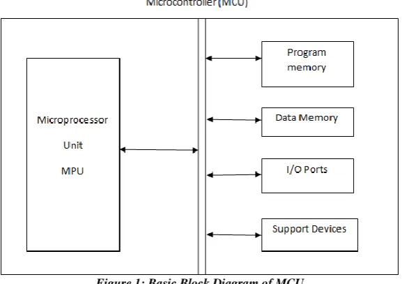
As the name implies, a single-chip computer is an entire computer system that lies within the confines of an integrated circuit (IC) chip [3]. The microcontroller existing on the encapsulated sliver of silicon has features and similarities to our standard personal computer (PC). Primarily the microcontroller is capable of storing and running a program (most important feature) [4] [3]. The microcontroller contains a central processing unit (CPU), random access memory (RAM), read only memory (ROM), input/output (I/O) lines, serial and parallel ports, timers, and sometimes [5] Other built-in peripherals like analog-to-digital (A/D) and digital-to-analog (D/A) converters[6].
The microcontroller’s ability to store and run unique programs makes it extremely versatile [7]. For instance, one can program a microcontroller to make decisions (perform functions) based on predetermined situations (I/O line logic) and sensor readings [8]. Its ability to perform math and logic functions allows it to mimic sophisticated logic and electronic circuits [9]. Still other programs can make the microcontroller behave like a neural or fuzzy logic controller [10].
G
lobal
J
ournal of
E
ngineering
S
cience and
R
esearch
M
anagement
Different Microcontrollers AVR microcontroller PIC Microcontroller 89c51 series
AVR Microcontroller:
AVR Microcontroller has the many of the advantage over the conventional Microcontrollers such as
RISC Architecture with mostly fixed-length instruction, Load store memory access, and 32-general purpose register. A large register set means that variables can be stored inside the CPU rather than storing the variables in the memory.
Two stage pipe line that speeds up execution.
Wide variety of on chip peripherals, including digital I/O, ADC, EEPROM, Timer, UART, RTC Timer, Pulse Width modulator etc.
Internal data and program memory. In system programmable.
Up to 12 times performance speedup over conventional CISC controllers.
PIC Microcontroller
PIC microcontrollers have a very small set of instructions, leading some to consider them RISC devices. However, the PIC architecture does not reflect many of the advantages of RISC design. For example:
PIC does not have a load-store architecture, as memory is directly referenced in arithmetic and logic operations
it has a single working register, while RISC designs typically include 16 or more general purpose registers
Its addressing modes are not orthogonal, since some instructions can address RAM or immediate data, while others can only use the working register
Bank switching is required to access the entire RAM of many PIC devices, making the development of libraries of position-independent code complex and inefficient
A stack cannot be implemented efficiently, so it is difficult to generate reentrant code These properties have made it difficult to develop compilers that target PIC microcontrollers.
89C51 Microcontroller
This is the most popular 8-bit microcontroller.
4K Bytes of In-System Reprogrammable Flash Memory 128 byte Internal RAM
Four 8-bit I/O ports Two 16-bit Timer/Counters Six Interrupt Sources
Programmable Serial Channel
Wireless Communication
and wireless broadband Internet.
Radio Frequency
In the United States the Federal Communication Commission regulates the use of industrial, scientific and medical (ISM) radio bands. The ISM radio band was originally reserved internationally for the license-free use of RF electromagnetic fields. In license-free radio bands, users don’t have to purchase a license and the spectrum is widely available.
In recent years, the ISM license-free radio frequencies have been used for communication technologies such as Wi-Fi, Bluetooth and ZigBee. The more commonly used license-free RF bands are 900MHz, 1.8GHz, and 5.8GHz. The two methods for radio frequency modulation in the unlicensed 2.4GHz ISM band are frequency-hopping spread spectrum (FHSS) and direct-sequence spread spectrum (DSSS). FHSS is a spread-spectrum method of transmitting radio signals by rapidly switching a carrier among many frequency channels, using a pseudorandom sequence known to both transmitter and receiver. DSSS is a modulation technique in which the transmitted signal takes up more bandwidth than the information signal that is being modulated. The 900MHz radio frequency band is for unlicensed use only in North America, Australia and Israel, while the 2.4 GHz radio frequency band can be used worldwide (including North America, Australia and Israel).
Fi is a wireless networking protocol based on the IEEE 802.11 specifications. The primary motivation for Wi-Fi is data throughput. Wi-Wi-Fi is typically used to connect computers to wireless local area networks (WLAN) and indirectly to the internet. Wi-Fi devices transmit at frequencies of 2.4 GHz or 5 GHz. Wi-Fi uses DSSS, with each channel being 22 MHz wide, allowing up to three evenly-distributed channels to be used simultaneously without overlapping each other.
Bluetooth
Many companies such as Sprint, Motorola and Microsoft have incorporated Bluetooth into mobile phones, portable computers, cars, stereo headsets, MP3 players, etc. Bluetooth is a short range low power, low cost communication standard that uses radio technology. Originally, in 1984 Bluetooth was envisioned as a cable-replacement technology. In 1999 seven companies teamed up and formed a group called the Bluetooth Special Interest Group (SIG). The SIG developed Bluetooth into an attractive compatible wireless standard.
Three different classes of Bluetooth radios exist, class 1, class 2, class 3. Each with different operating ranges. A class 1 radio has an operating range of up to 100 meters, class 2 up to 10 meters, class 3 up to 1 meter. There are two core specification versions of Bluetooth, both with different data rates; Version 2.0 has an enhanced data rate of 3 Mbps and Version 1.2 has a basic data rate of 1 mbps. Batteries powering a Bluetooth device have a very short life expectancy, usually a few days.
Bluetooth devices can from a personal are network called a piconet. A piconet is an ad-hoc computer network of devices using Bluetooth technology protocols to allow one master device to interconnect with up to seven active slave devices. Piconets can communicate with each other, thus allowing devices that are out of range to communicate through several hops from one piconet to the other.
G
lobal
J
ournal of
E
ngineering
S
cience and
R
esearch
M
anagement
Bluetooth protocol stack is illustrated in the radio layer is primarily concerned with the design of the Bluetooth transceivers. The baseband layer defines how Bluetooth devices search for and connect to other devices. The master and slave roles are defined her, as are the frequency-hopping sequences used by devices. The baseband layer supports two types of links: Synchronous Connection Oriented (SCO) and Asynchronous Connection Less (ACL). SCO links are characterized by a periodic, single-slot packet assignment, and are primarily used for voice transmission that requires fast, consistent data transfer.
A device with an ACL link can send variable length packets of 1, 3 or 5 time-slot lengths. The link manager layer manages the properties of the air interface link between devices. The logical link control and Adaptation Protocol (L2CAP) layer provides the interface between the higher-layer protocols and the lower-layer protocols. L2CAP allows multiple protocols and applications to share the air-interface. L2CAP is also responsible for packet segmentation and reassembly, and for maintaining the negotiated service level between devices. The Host Controller Interface (HCI) layer defines a standard interface for upper level applications to access the lower layers of the stack.
A Bluetooth transceiver uses frequency hopping-spectrum (FHSS) in the unlicensed 2.4 GHz ISM frequency band. This data transmission technique makes signals difficult to intercept because FHSS signals sound like momentary noise bursts. Typically, 79 channels are available for a Bluetooth device. A device can only operate on a channel for 0.4 seconds within a 30 second window, and transmits using pseudorandom hops across all 79 channels at a rate of 1600 hops per second.
Bluetooth devices use a polling technique to transmit packets. The master device transmits only in even numbered time slots. The slave devices transmit only in odd numbered time slots. A different frequency channel is use in each time slot.
Zigbee
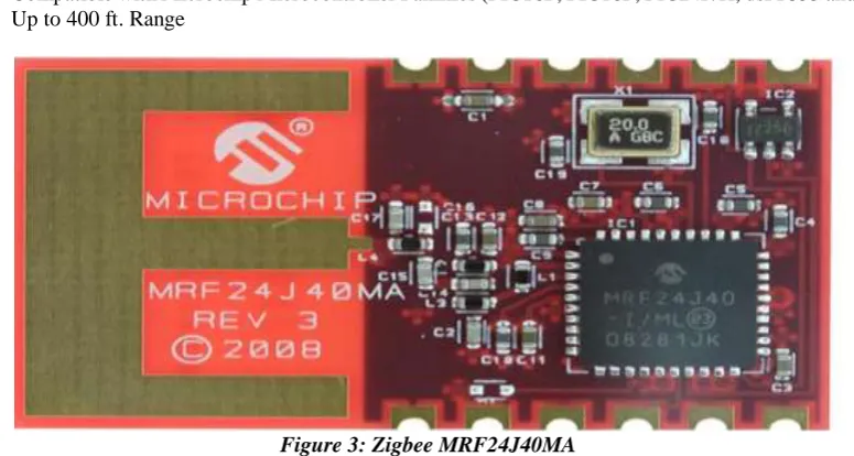
The MRF24J40MA is a 2.4 GHz IEEE Std. 802.15.4™ compliant, surface mount module with integrated crystal, internal voltage regulator, matching circuitry and PCB antenna. The MRF24J40MA module operates in the non-licensed 2.4 GHz frequency band and is FCC, IC and ETSI compliant. The integrated module design frees the integrator from extensive RF and antenna design, and regulatory compliance testing, allowing quicker time to market. The MRF24J40MA module is compatible with Microchip’s ZigBee®, MiWi™ and MiWi P2P software stacks.
The MRF24J40MA module has received regulatory approvals for modular devices in the United States (FCC), Canada (IC) and Europe (ETSI). Modular approval removes the need for expensive RF and antenna design and allows the end user to place the MRF24J40MA module inside a finished product and not require regulatory testing for an intentional radiator (RF transmitter).
A zigbee network usually consists of one master device one or more slave device and operational router. The master device responsible for establishing a network with a personal area network identifier the slave devices can be programmed to sleep so that battery power is conserved.
The wireless technology characteristic says that zigbee transmit at a slower data rate, 250 KBPS than the other wireless standards however this transmission rate is ideal for system that intermittently transmit small amounts of data. Because zigbee performs just a few specific, simple task the protocol stack can be as small as 28KB, therefore the system controller requires less energy and consumes less power. The small amounts of data that are transmitted also contribute to systems minimal energy consumption. Bluetooth device consumes more power because they are typically constant lay on and don’t spend much time sleeping whereas zigbee slave devices spend a majority of their time sleeping
Zigbee clearly has advantage over other wireless technique when network size is considered a zigbee network can deploy over 65500 sensor nodes within network system this nodes count gains over Bluetooth 7, Wi-Fi 32 by a sizeable margin on the attractive feature of zigbee is its ability to transmit data up to 300 meter or up to 30 times farther than Bluetooth and 3 times farther than Wi-Fi.
communicate directly with a coordinator or router. The Wi-Fi server communicate routes may exists. Only the node that data is intended for reacts in star topology ZigBee network contains one coordinator, no router and no of devices that are all within range of the coordinator. The third topology arranges communicate routers so that true exist exactly one route from one device to another
DIFFERENT TYPES OF WIRELESS COMMUNICATION
ZigBee 802.11 (Wi-Fi)
Bluetooth UWB (Ultra Wide Band)
Wireless USB
IR Wireless
Data Rate 20, 40, and 250 Kbits/s
11 & 54 Mbits/sec
1 Mbits/s 100-500 Mbits/s
62.5 Kbits/s
20-40 Kbits/s 115 Kbits/s 4 & 16 Mbits/s
Range 10-100 meters 50-100 meters 10 meters <10 meters 10 meters <10 meters (line of sight)
Networking Topology
Ad-hoc, peer to peer, star, or mesh
Point to hub Ad-hoc, very small
networks
Point to point
Point to point
Point to point
Operating Frequency
868 MHz (Europe) 900-928 MHz (NA), 2.4 GHz (worldwide)
2.4 and 5 GHz 2.4 GHz 3.1-10.6 GHz
2.4 GHz 800-900 nm
Complexity (Device and application impact)
Low High High Medium Low Low
Power Consumption (Battery option and life)
Very low (low power is a design goal)
High Medium Low Low Low
Security 128 AES plus application layer security
64 and 128 bit encryption
Other Information
Devices can join an existing network in under 30ms
Device connection requires 3-5 seconds
Device connection requires up to 10 seconds
Typical Applications
Industrial control and monitoring,
Wireless LAN connectivity,
Wireless connectivity between
Streaming video, home entertainmen
PC periphera l
G
lobal
J
ournal of
E
ngineering
S
cience and
R
esearch
M
anagement
sensornetworks, building automation, home control and
automation, toys, games
broadband Internet access
devices such as phones, PDA, laptops, headsets
t
applications
connectio ns
PDA, phone, laptop links
Zigbee MRF24J40MA
Features
IEEE Std. 802.15.4™ Compliant RF Transceiver
Supports ZigBee®, MiWi™, MiWi™ P2P and Proprietary Wireless Networking Protocols
Small Size: 0.7” x 1.1” (17.8 mm x 27.9 mm), Surface Mountable
Integrated Crystal, Internal Voltage Regulator, Matching Circuitry and PCB Antenna
Easy Integration into Final Product – Minimize Product Development, Quicker Time to Market Radio Regulation Certification for United States (FCC), Canada (IC) and Europe (ETSI)
Compatible with Microchip Microcontroller Families (PIC16F, PIC18F, PIC24F/H, dsPIC33 and PIC32) Up to 400 ft. Range
Figure 3: Zigbee MRF24J40MA
Schematic Description
The MRF24J40MA module is based on the Microchip Technology MRF24J40 IEEE 802.15.4™ 2.4 GHz RF Transceiver IC. The serial I/O (SCK, SDI, SDO and CS), RESET, WAKE and INT pins are brought out to the module pins. The SDO signal is tri-state buffered by IC2 to solve a silicon erratum, where the SDO signal does not release to a high-impedance state, after the CS pin returns to its inactive state. Crystal, X1, is a 20 MHz crystal with a frequency tolerance of ±10 ppm @ 25°C to meet the IEEE Std. 802.15.4 symbol rate tolerance of ±40 ppm. A balun is formed by components: L1, L3, C2 and C14. L2 is an RF choke and pull-up for the RFP and RFN pins on the MRF24J40. C15 is a DC block capacitor. A low-pass filter is formed by components: L4, C16 and C17. The remaining capacitors provide RF and digital bypass.
The ZigBee is a collection of companies that have teamed up to promote a wireless communication standard based on the IEEE 802.15.4 standard. The 802.15.4 specification covers the PHY and MAC hardware, while ZigBee starts at the Media Access Control (MAC) layer and adds a Data Link layer, a Network Layer, and an Application Interface. Thus, ZigBee encapsulates nearly the entire communication process from the end user's application.
for a system is about .01%. This means the system has an effective power consumption of 30uW in contrast to a active Bluetooth node which consumes about 30 mW of continuous power.
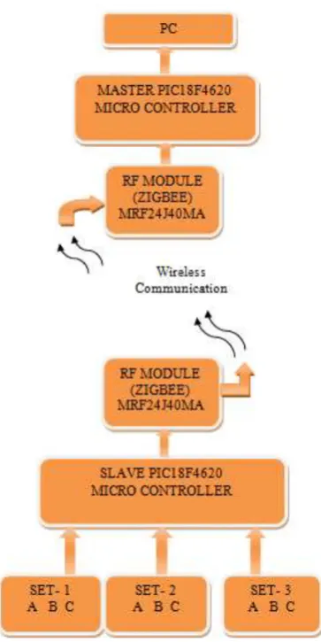
Hardware Design
Design Specification
One master controller (PIC18F4620) and one slave controller (PIC18F4620) Two ZIGBEE trans receiver module (MRF24J40MA)
1 sets of switches, contents 4 switches Computer for out put display
System Level Diagram.
Figure 4: System Level Diagram
PIC18F4620
Features of PIC18f4620
C Compiler Optimized Architecture:
Optional extended instruction set designed to optimize re-entrant code 100,000 Erase/Write Cycle Enhanced Flash Program Memory Typical 1,000,000 Erase/Write Cycle Data EEPROM Memory Typical Flash/Data EEPROM Retention: 100 Years Typical
Self-Programmable under Software Control Priority Levels for Interrupts
G
lobal
J
ournal of
E
ngineering
S
cience and
R
esearch
M
anagement
Single-Supply 5V In-Circuit Serial Programming™ (ICSP™) via Two Pins In-Circuit Debug (ICD) via Two Pins
Wide Operating Voltage Range: 2.0V to 5.5V
Programmable Brown-out Reset (BOR) with Software Enable Option High-Current Sink/Source 25 mA/25 mA
Three Programmable External Interrupts Four Input Change Interrupts
Up to 2 Capture/Compare/PWM (CCP) modules, one with Auto-Shutdown (28-pin devices) Enhanced Capture/Compare/PWM (ECCP) module (40/44-pin devices only):
One, two or four PWM outputs Selectable polarity
Programmable dead time Auto-shutdown and auto-restart
Master Synchronous Serial Port (MSSP) module Supporting 3-Wire SPI (all 4 modes) and I2C™ Master and Slave modes
Enhanced Addressable USART module:
Supports RS-485, RS-232 and LIN/J2602
RS-232 operation using internal oscillator block (no external crystal required) Auto-wake-up on Start bit
Auto-Baud Detect
10-Bit, up to 13-Channel Analog-to-Digital (A/D) Converter module: Auto-acquisition capability
Conversion available during Sleep Dual Analog Comparators with Input Multiplexing
Programmable 16-Level High/Low-Voltage Detection (HLVD) module: Supports interrupt on High/Low-Voltage Detection
CONCLUSION
This paper delineate the mixture Zigbee development of Wireless Data Transfer gets to be essential interest for the mechanical application. The effective transmitter and collector unit with high preparing capacities for both the modules which can transform the got data give enhancement result has ended up need. These things personality a top priority we have think of a thought to transmit and get information remote utilizing ZigBee and PIC controller which for the most part suffices the above necessity.
REFERENCES
1. Ajay V Deshmukh, Microcontrollers Theory and Application, Tata McGraw- Hill Publishing Company Limited
2. Richard Barnett, Larry O’cull, Embedded C Programming and the Microchip PIC.
3. Chien C.-N., Hsu, H.- W., Jang J.-K., Rau C.-L., and Jaw F.-S., “Microcontroller-based wireless recorder for biomedical signals,” Proceedings of the 2005 IEEE Engineering in Medicine and Biology 27th Annual Conference Shanghai, China, September 1-4, 2005.
4. www.datasheetcatalog.org/datasheet/texasinstruments/max232.pdf
5. Geer, D., “Users Make a Beeline for ZigBee Sensor Technology,” IEEE Computer Society, Vol. 38, pp 16-19, December 2005.
6. Muhammad Ali Mazidi,Janice Gillispie Mazidi,Rolin D. McKinlay, The Microcontroller and Embedded Systems,2nd Edition,Prentice Hall (page no.24)
7. http://www.microchip.com/wwwproducts/Devices.aspx?dDocName=en535967
8. http://ww1.microchip.com/downloads/en/DeviceDoc/39626e.pdf
9. http://www.microchip.com/wwwproducts/Devices.aspx?dDocName=en535967