ISSN : 2455-9679
[Miteshet al. , 4(8), Aug 2019] Impact Factor : 2.865
IJRTSM
INTERNATIONAL JOURNAL OF RECENT TECHNOLOGY SCIENCE & MANAGEMENT
“PARAMETRIC STUDY OF SWIRL DIFFUSER DESIGN FOR AIR FLOW IN AIR-
CONDITIONING OF AN AUTOMOBILE”
Mitesh Kumar
1,
Prof. Ravindra Mohan
21M-Tech Scholar, Department of Mechanical Engineering, IES, College Bhopal, MP, India 2
Assistant Professor, Department of Mechanical Engineering, IES, College Bhopal, MP, India
ABSTRACT
In this thesis, the variation in temperature of conditioned air and improvement in thermal human comfort by adopting different models of floor swirl diffuser are investigated. Different models of floor swirl diffuser having different slot angles of 12°, 13° and 14°are modeled in Creo 4.0 software. Experimental analysis is performing on the models by varying distance of fluid 0.8ft, 1.5ft, 2.2ft, 2.9ft, 3.6ft and 4.3ft to determine temperature . The results from this dissertation work show that a car installed with swirl diffuser at the outlet of A.C. can improve air quality because the contaminant concentration in the breathing zone is lower than that of mixing system.
Key Words: Temperature, Air, Creo 4.0 Software, Swirl Diffuser, A.C., Human Comfort
I.
I
NTRODUCTIONAir conditioning
It is the procedure of simultaneous control of temperature, humidity, tidiness and air development inside a room. On the off chance that there ought to emerge an event of the machine sections, close by temperature, humidity (dampness content in the air) furthermore should be controlled and for the comfort of individuals nearby these two noteworthy parameters, air development and neatness in like manner expect a fundamental activity. Air conditioning, subsequently, is a progressively broad perspective which examines the synchronous control all of mechanical parameters which are fundamental for the comfort of individuals or animals or for the most ideal display of some advanced or consistent procedure [8]. In specific applications, even the control of air weight falls under the area of air conditioning. It is to be seen that refrigeration that is control of temperature is the most noteworthy piece of air conditioning.
ISSN : 2455-9679
[Miteshet al. , 4(8), Aug 2019] Impact Factor : 2.865
II. MODELING
&
SIMULATION
2.1 Development of diffuser model on Cre-o software
1. The procedure involved in development of diffuser model on Cre-o software is as follows: 1. Select new working file with type part and subtype solid. Name the working file with extension .prt and select the working units millimeter, Newton and second.
2. Sketch the diffuser with standard dimension and produce a solid model by using extrude command.
3. Diffuser can be made hollow by using shell command.
4. Cut the round slots over the diffuser top surface by using material removal command. 5. The slots cut will be repeated on the top surface by using pattern command about the axis.
6. Slots cut on the upper surface can be drafted at different angle by using draft command. 7. Rounded portion of the slot can be drafted by using protrusion command.
8. Sharp corners and edges present in diffuser can be removed by using round and chamfer command.
2.2 Model Tree for diffuser
The model tree showing various operations involved while modeling diffuser is as follows
ISSN : 2455-9679
[Miteshet al. , 4(8), Aug 2019] Impact Factor : 2.865
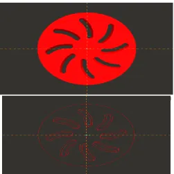
2.1.1 The 12⁰ Swirl Diffuser
Fig. 2.2 The 12⁰ Swirl Diffuser 2.1.2 The 13⁰ Swirl Diffuser
Fig. 2.3 The 13⁰ Swirl Diffuser 2.1.3 The 14⁰ Swirl Diffuser
ISSN : 2455-9679
[Miteshet al. , 4(8), Aug 2019] Impact Factor : 2.865
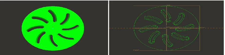
2.3 Cre-o design of 12⁰ floor swirl diffuser
2.3.1 Dimensional view showing draft angle of slot
Fig. 2.5 Dimensional view showing draft angle of slot 2.3.2 Top view of 12⁰ floor swirl diffuser in solid and wireframe model-
Fig. 2.6 Top view of 12⁰ floor swirl diffuser in solid and wireframe model
2.3.3 Front view of 12⁰ floor swirl diffuser in solid and wireframe model
ISSN : 2455-9679
[Miteshet al. , 4(8), Aug 2019] Impact Factor : 2.865
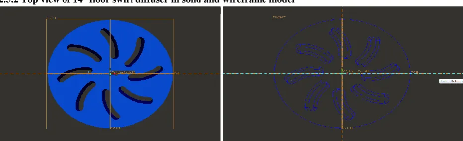
2.4 Cre-o design of 13⁰ floor swirl diffuser
2.4.1 Three dimensional view showing draft angle of slot
Fig. 2.8 Three dimensional view showing draft angle of slot
2.4.2 Top view of 13⁰ floor swirl diffuser in solid and wireframe model
Fig. 2.9 Top view of 13⁰ floor swirl diffuser in solid and wireframe model
2.4.3 Front view of 13⁰ floor swirl diffuser in solid and wireframe model
Fig. 2.10 Front view of 13⁰ floor swirl diffuser in solid and wireframe model
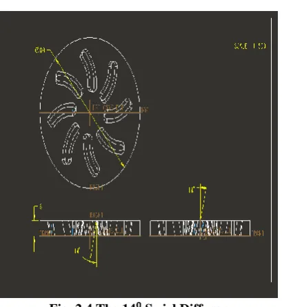
2.5 Cre-o design of 14⁰ floor swirl diffuser
ISSN : 2455-9679
[Miteshet al. , 4(8), Aug 2019] Impact Factor : 2.865
Fig. 2.11 Three dimensional view showing draft angle of slot
2.5.2 Top view of 14⁰ floor swirl diffuser in solid and wireframe model
Fig. 2.12 Top view of 14⁰ floor swirl diffuser in solid and wireframe mode l
2.5.3 Front view of 14⁰ floor swirl diffuser in solid and wireframe model
Fig. 2.13 Front view of 14⁰ floor swirl diffuser in solid and wireframe model
The investigation is performed in the workshop lab of Bhagawati Frontline Motorizer Private Limited Singrauli, Madhya Pradesh . The target of this examination is to discover the air flow example and its conveyance through various swirl diffusers introduced in vehicle for air-conditioner. The analysis depends on anticipating the nature and conduct of air diffused by three unique sorts of swirl diffusers having spaces with draft point of 12⁰, 13⁰ and 14⁰ individually under various working and flow conditions.
ISSN : 2455-9679
[Miteshet al. , 4(8), Aug 2019] Impact Factor : 2.865
III.
EXPERIMENTAL
ASSUMPTIONS
In the early structure arrange, without exploratory information support, a few suppositions must be taken dependent on the experience and comparable examinations done in this field. Following suppositions are connected in the examination of exploratory and numerical investigation.
• Metabolic rate and inclination of shutting in the workplace differs from the individuals to individuals. The standard qualities for metabolic rate and shutting variable are to be considered. The movement of an inactive tenant is evaluated to be 1.2 met and the dress protection is 1.0 clo in winter and 0.5 clo in summer.
Ventilation adequacy for DCV is assessed to be 1.0, for what it's worth for the blending ventilation. The exploratory set-up is arranged in a spotless zone with brilliant air quality.
Acrylic sheet wooden room is shut while playing out the test and heat move from room entryway because of spillage is ignored.
We have expected that the situation of the live concerning sun course and elevation is indistinguishable for heat load count. So no impact has been considered.
Only reasonable heat of air is estimated for computation dismissing dormant heat.
3.1 Experimental Set-up
It comprises of three unique models of swirl diffuser introduced in the vehicle for air dissemination inside the vehicle space. The adapted air from air conditioner is provided through the diffuser. A bulb of 1000W is set inside the vehicle to give a heat load. Bulb is set close to the area Y2. A temperature detecting instrument with six thermocouple wires is put inside the vehicle to quantify the temperature at six areas vertically at a separation of 0.7 feet.
There are six areas inside the vehicle where readings of temperature have to be noted and the variation in temperature of air is to be studied.The various components and parts of the experimental set-up are shown in following figures.
Fig.3.1 12⁰ Swirl Diffuser Fig.3.2 13⁰ Swirl Diffuser
ISSN : 2455-9679
[Miteshet al. , 4(8), Aug 2019] Impact Factor : 2.865
Fig.3.5 13⁰ Swirl Diffuser in installed position Fig.3.6 14⁰ Swirl Diffuser in installed position
Fig.3.9 HPS Bulb of heat load capacity 1000W Fig.3.10 Wireframe model of the experimental set-up
3-D view of the experimental set-up and actual front view of the experimental set-up is shown in Fig.5.11, Fig.5.12 and Fig.5.13 respectively.
Fig.3.7 Digital Temperature Indicator
showing temperature
at various locations
ISSN : 2455-9679
[Miteshet al. , 4(8), Aug 2019] Impact Factor : 2.865
3.2 Experimental instrumentation 3.2.1 Temperature indicator
The Digital Temperature Indicator gives an advanced sign of temperature with a goals of 1° C or 0.1° C. Thermocouple break protection and automatic cold junction compensation are added features of this instrument.
Fig.3.14 Temperature indicator Fig.3.15 Switch changer
Fig.3.11 Front view of the experimental
set-up
Fig.3.12 Transparent 3-D view of
experimental set-up showing locations
below car seat
Fig.3.13
Transparent
3-D
view
of
ISSN : 2455-9679
[Miteshet al. , 4(8), Aug 2019] Impact Factor : 2.865
3.2.2 Temperature switch changer
Temperature switch changer is used to controller and change the indication of the temperature at various point at which it is attached.
3.3 Swirl Diffusers
3.3.1 The 120 Swirl diffuser
It is made of plywood of circular cross-section 80 mm diameters and thickness 8mm. Curved slots are cut on the top surface. Curved slots are cut with inner radius 75mm and outer radius 85mm. Curved slots are drafted through an angle of 120 for producing swirl action of diffused air. The draft in the slots is provided with the help of file.
Fig. 3.16 3-D view of 120 Swirl Diffuser 3.3.2 The 130 Swirl diffuser
It is made of plywood of circular cross-section 80 mm diameters and thickness 8mm. Curved slots are cut on the top surface. Curved slots are cut with inner radius 75mm and outer radius 85mm. Curved slots are drafted through an angle of 130 for producing swirl action of diffused air. The draft in the slots is provided with the help of file.
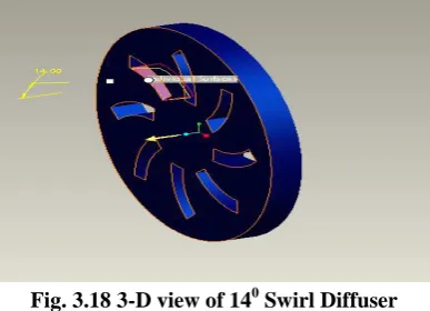
Fig. 3.17 3-D view of 130 Swirl Diffuser 3.3.3 The 140 Swirl diffuser
It is made of plywood of circular cross-section 80 mm diameters and thickness 8mm. Curved slots are cut on the top surface. Curved slots are cut with inner radius 75mm and outer radius 85mm. Curved slots are drafted through an angle of 140 for producing swirl action of diffused air. The draft in the slots is provided with the help of file.
Fig. 3.18 3-D view of 140 Swirl Diffuser 3.4 Experiment Method
ISSN : 2455-9679
[Miteshet al. , 4(8), Aug 2019] Impact Factor : 2.865
and X6].These points are taken at a distance of 1.5 foot apart. Points Y1, Y2 and Y3 are taken along longitudinal axis from the front of car and points X1, X2, X3, X4, X5 and X6 are taken along X-axis at the roof of car. A bulb of load capacity 1000W is placed near the test location Y2. After all the arrangement a temperature measuring stand having 6 thermocouples is placed at different test point and record the temperature of air by using switch changer and temperature indicator. The thermocouples are placed at a distance of 0.7 feet apart. The temperature readings are noted for different swirl diffusers at various test locations with and without heat load. The variation in temperature of diffused air with height and along longitudinal axis from the front of car is evaluated for different diffusers at various locations.
IV.
EXPERIMENT
RESULTS
The results of experiments are presented in two parts: requirement of the air conditioner size for the particular inside car conditions by the cooling load calculation and thermal comfort environment according to the temperature variation inside the car with different diffusers. Due to different slot angle geometry of swirl diffusers, flow pattern of diffused air inside the room changes. The air is circulated inside the car through different diffusers. As a result the temperature of air inside the car varies which we have recorded at nine different locations. The variation in temperature with respects to height and also with respects to horizontal distance from front to back of car is tabulated for each swirl diffuser with and without heat load. The study helps in comparing the performance of different swirl diffusers under different operating conditions. From the graphs plotted it is observed that minimum variation in temperature is obtained with 13⁰ swirl diffuser and the uniformity in temperature is obtained.
Various data has been recorded with different swirl diffusers under different operating conditions and are tabulated as shown below in the tables.
4.1.1 Experimental Readings: Initial Car Temperature = 32⁰C
Car Temperature with load 1000W with air conditioner in off condition= 38⁰C
Fig.4.1 Variation in temperature vs. distance from front of car in feet at location Y1 without load.
Fig.4.2 Variation in temp. vs. distance from front of car in feet at location Y1 with load 1000W.
0 5 10 15 20 25 30
0 1 2 3 4 5
Tem p e ratu re (⁰C)
Distance from front of car (ft.)
Diffuser 12⁰ Diffuser 13⁰ Diffuser 14⁰ 0 5 10 15 20 25 30
0 1 2 3 4 5
Tem p e ratu re (⁰C)
Distance from front of car (ft.)
Diffuser 12⁰
Diffuser 13⁰
ISSN : 2455-9679
[Miteshet al. , 4(8), Aug 2019] Impact Factor : 2.865
Fig.4.3 Variation in temperature vs. distance from front of car in feet at location Y2 without load.
Fig.4.4 Variation in temp. vs. distance from front of car in feet at location Y2 with load 1000W.
Fig.4.5 Variation in temperature vs. distance from front of car in feet at location Y3 without load.
Fig.4.6 Variation in temp. vs. distance from front of car in feet at location Y3 with load 1000W.
0 5 10 15 20 25 30
0 2 4 6
Di st an ce fr o m fr o n t o f car ( ft .) Temperature (⁰C) Temperature (⁰C) 12⁰ Temperature (⁰C) 13⁰ Temperature (⁰C) 14⁰ 0 5 10 15 20 25 30 35
0 2 4 6
Te m p e rat u re ( ⁰C )
Distance from front of car (ft.)
Temperature 12⁰ Temperature 13⁰ Temperature 14⁰ 0 5 10 15 20 25 30
0 2 4 6
Tem p e ratu re (⁰C)
Distance from front of car (ft.)
Temperature (⁰C) 12⁰ Temperature (⁰C) 13⁰ Temperature (⁰C) 14⁰ 0 5 10 15 20 25 30 35
0 2 4 6
Tem p e ratu re (⁰C)
Distance from front of car (ft.)
Temperature 12⁰
Temperature 13⁰
ISSN : 2455-9679
[Miteshet al. , 4(8), Aug 2019] Impact Factor : 2.865
Fig.4.7 Variation in temperature vs. height at location X1 without load.
Fig.4.8 Variation in temperature vs. height at location X1 with load 1000W.
ISSN : 2455-9679
[Miteshet al. , 4(8), Aug 2019] Impact Factor : 2.865
Fig.4.10 Variation in temperature vs. height at location X2 with load 1000W.
Fig.4.11 Variation in temperature vs. height at location X3 without load.
ISSN : 2455-9679
[Miteshet al. , 4(8), Aug 2019] Impact Factor : 2.865
Fig.4.13 Variation in temperature vs. height at location X4 without load.
Fig.4.14 Variation in temperature vs. height at location X4 with load 1000W.
ISSN : 2455-9679
[Miteshet al. , 4(8), Aug 2019] Impact Factor : 2.865
Fig.4.16 Variation in temperature vs. height at location X5 with load 1000W.
Fig.4.17 Variation in temperature vs. height at location X6 without load.
Fig.4.18 Variation in temperature vs. height at location X6 with load 1000W
V
CONCLUSION
AND
FUTURE
SCOPE
5.1 Conclusion:
ISSN : 2455-9679
[Miteshet al. , 4(8), Aug 2019] Impact Factor : 2.865
The maximum variation in temperature is obtained at location Y2. This happens due to presence of bulb of load capacity 1000W near location Y2. As we move away from the heat source variation in temperature reduces and we obtained almost uniform temperature at the upper region of the experimental set-up. We have compared the performance of different swirl diffuser models having slot with draft angle 12⁰, 13⁰ and 14⁰ under different operating conditions and the best performance is obtained with 13⁰ swirl diffuser.
REFERENCES
1. H.T. Xu, and J.L. Niu “A NEW METHOD OF CFD SIMULATION OF AIRFLOW CHARACTERISTICS OF SWIRLING FLOOR DIFFUSERS” Eighth International IBPSA Conference Eindhoven, Netherlands August 11-14, 2003
2. Josephine Lau, Qingyan Chen, Floor-supply displacement ventilation for workshops, January 2006, ELSEVIER, Science Direct.
3. Liu Jinping, Wu Yanfang, Experimental study on airflow fluctuation characteristic of an underfloor air supply terminal unit, July 2010, ELSEVIER, Science Direct.
4. Jae Dong Chung, Hiki Hong, Hoseon Yoo, Analysis on the impact of mean radiant temperature for the thermal comfort of underfloor air distribution systems, 2010
5. Jae-Hyung Kim and Heuy-Dong Kim, Effect of diffuser angle on the discharge coefficient of miniature critical nozzles, May 2010, Springer.
6. Prasanta K. Sinha, Bireswar Majumdar “Computational Investigation of Performance Characteristics throughAnnular Diffuser” International Journal of Engineering Research and Applications (IJERA) ISSN: 2248-9622 www.ijera.comVol. 1, Issue 3, pp.830-836
7. B. Sajadi, M.H. Saidi, A. Mohebbian, Numerical investigation of the swirling air diffuser: Parametric study and optimization, January 2011, ELSEVIER, Science Direct.
8. Kwang Ho Lee, Sang Min Kim, Jong Ho Yoon, Supply air temperature impact in underfloor air distribution systems under Korean climatic conditions: Energy, humidity and comfort, October 2012, ELSEVIER, Science Direct.
9. Xue, G., Lee, K., Jiang, Z. and Chen, Q. 2012. Thermal environment in indoor spaces with under-floor air distribution systems: 2. Determination of design parameters (RP-1522).Submitted to HVAC&R Research.
10. Ehsan Tavakoli, Reza Hosseini, Large eddy simulation of turbulent flow and mass transfer in far-field of swirl diffusers, December 2012, ELSEVIER, Science Direct.