Slope Detection Based on Grating Sensors
https://doi.org/10.3991/ijoe.v14i11.9520Lin Huang(*), Fengyin Liu, Jun Li
Xi’an University of Technology, Xi’an, China
Abstract—Because slope detection is often subject to various electromag-netic disturbances and weather limitations, there is an urgent need to develop a monitoring system that has the advantages of strong anti-electromagnetic inter-ference capability, long service life, and small external environmental impact. Based on this demand, a real-time slope monitoring system based on fiber Bragg grating angle, crack, and osmotic pressure sensors is designed. The design idea is to use the sensitivity of FBG to the external stress, and the angle and crack penetrating pressure information are obtained from the offset of wavelength in different sensors to determine the stability of the slope. The design and imple-mentation of the FBG slope monitoring system can better solve the existing prob-lems in the slope monitoring, improve the ability to predict dangers, and strengthen the safety monitoring capability. The utility value of the system is high.
Keywords—slope detection, FBG, cracks, penetration
1
Introduction
the formation of a unified market and regional division of labor cooperation. The safe operation of railways is closely related to the rapid development of the country. The flexibility of roads and obvious advantages in short-distance transportation cannot hide the disadvantages caused by factors such as cost and environmental protection. How-ever, highways are also an indispensable part of the country’s rapid economic develop-ment. At the same time, various dam projects continue to be built, and the stability of the dam is directly related to the safety of life and property of millions of people down-stream. Therefore, stability monitoring of dams is also necessary.
The development of the industrial revolution has a close relationship with coal and people's lives. After coal is mined out of the ground, it accumulates at a fixed location. This fixed location is not arbitrarily selected. People call it a tailings pond, and the stability of the accumulation is very important. A tailings pond refers to a site con-structed by intercepting a valley or enclosure to store metal or non-metal mines for ore sorting to discharge tailings or other industrial waste. Tailings ponds are very common in our country. As long as there are mined ore, there will be a tailings pond basically. Tailings ponds have high potential energy and there are safety risks. Once an accident occurs, it will easily cause major losses. Among all accident hazards, the accident caused by the tailing pond ranks 18th. It can be imagined that the tailings pond is also a huge security risk in the world.
2
Literature review
2.1 Slope detection research status
Slope refers to the free face with a certain slope formed by artificial excavation or natural action of a mountain, soil, etc. Therefore, according to the form of the slope, it can be divided into natural slopes and artificial slopes. Generally, soil slopes with a height of more than 20 meters and rock slopes with a height of more than 30 meters are considered as high slopes. Slope works are common in people's daily lives - slopes formed by the excavation of dam reservoirs, slopes along traffic lines, slopes of urban construction near the mountains, etc. The main forms of traffic engineering in moun-tainous areas are elevated bridges, tunnels, and slopes, and it is difficult to find a flat section that can be directly tracked and built. For the railway lines, the survey and de-sign lines should be avoided as far as possible to a serious geological hazard zone. However, due to the fact that the railway line itself needs to have the characteristics of straight line access and minimum turning radius, the civil engineering along the railway is more complicated than the highway. For the three projects of bridges, tunnels and slopes, the stability of the slope is particularly prominent, and the safety threat to the traffic lines is greatest.
are being continuously put into slope projects. The two most important aspects of slope monitoring are deformation displacement monitoring and stress state monitoring.
Naranjo et al. (2017) of Cambridge University used the distributed optical fiber sen-sor system to make a deep inclinometer to monitor the anti-slide piles on the slope and compare the deformation of the anti-slide piles to verify the feasibility of fiber-optic sensing for deep displacement measurements [1].
In the same year, Li et al. (2016) embedded 16 encapsulated fiber grating arrays in concrete strain piles to monitor the temperature and strain changes during the casting process and subsequent solidification and achieved good monitoring results [2].
Yuvaraja et al. (2017) proposed a fiber grating slope in-situ inclinometry technology and a difference equation to derive the relationship between fiber grating strain and bending deformation on an inclinometer tube, and the fiber grating inclinometer was applied to the actual project [3].
Domestically, Nanjing University has conducted more research and application of BOTDR technology on slope and other civil engineering projects. For example, Zhu et al. (2017) designed a slope model loading monitoring network based on the Brillouin optic time domain reflectometer (BOTDR) technology. The sensor network can accu-rately analyze the area where the anomaly occurred and the magnitude of the strain [4]. Thang et al. (2016) installed the designed BOTDR deformation monitoring system in the broken body of the actual project. The deformation of the slope was implemented with distributed monitoring and achieved good results [5].
2.2 The status of engineering application of optical fiber sensors
Optical fiber sensors are valued because of their advantages such as small size, light weight, freedom from electromagnetic interference, large-scale network measurement, and long-distance transmission of optical signals along optical fibers. Optical fiber sensing technology has developed rapidly in military, large-scale structural engineer-ing, civil engineerengineer-ing, and large-scale mechanical equipment. Fiber grating sensing is an important aspect in the field of fiber optic sensing. Research in this field has been very hot at home and abroad. In the past two decades, the fiber bragg grating sensing technology has been widely promoted and and has been increasingly applied in such fields as large-scale civil engineering and mechanical equipment.
Ferng and Khoa (2016) developed a new type of fiber grating strain sensor and tem-perature sensor, and applied to measure dynamic strain, static strain and temtem-perature on a freeway bridge. The research and application results proved that as long as the fiber bragg grating is properly packaged, it can be effectively applied in harsh environ-ments such as bridge projects [6].
Rao and Kar (2018) installed more than forty fiber grating sensors on the TsingMa bridge's slings, rocker supports, and frame beams to perform structural health monitor-ing. The outstanding performance of FBG sensors is consistent with the set of Windand Structural Health System installed on the bridge [7].
performance were selected to be installed inside the box girders of the bridge to monitor the strain distribution of the bridge during the process of train operation.
The research time of fiber grating sensing technology in China is almost synchro-nized with that of foreign countries. Due to the impact of China's overall technology, the level of fiber-optic sensing is not as good as that of foreign countries. However, many enterprises, universities and research institutions still conduct research and achieve impressive results.
Zhu et al. (2017) installed a fiber grating vibration sensor on the sling of the Wuhan Yangtze River Bridge and reversed the pulling force of the cable according to the string vibration frequency method to obtain the load distribution of the cable under different driving conditions. The important parameters of the bridge operation have been ob-tained to provide effective scientific data for mastering the operational status and struc-tural maintenance of the bridge [9]. The Institute of Engineering and Optoelectronics, founded by Wuhan University of Technology, has conducted extensive research on structural health monitoring in the field of civil engineering and installed a long-term fiber grating safety monitoring system on several domestic bridge projects.
Gomez and Tao (2017) used fiber bragg grating sensors to design anchor dynamom-eters and an optical fiber grating inclinometer, which were applied to the health moni-toring of the high-slope engineering of the Pantian Expressway [10]. Taking the Yiwan Railway Project as the engineering background, a corresponding fiber grating sensor monitoring technology was proposed for several measures of the slope treatment of the line, mainly including anchor pile stress monitoring, protection network cable pull rope tension monitoring and earth pressure monitoring. It was used to assess deformation, stress and changes in the surrounding environment of the slope and support structure.
3
Research on key technology of slope deformation monitoring
based on fiber bragg grating
3.1 The overall design of the system
The FBG sensor-based slope monitoring system uses sensors to detect changes in the characteristic cracks, angles, and osmotic pressures of the slope. The slope is eval-uated by the calculation of transmitted information.
In this system, the FBG sensor is used to read the feature quantity signal, and the optical signal is sent to the MCU through demodulation processing. The MCU then reprocesses the transmitted signal and distributes it to different peripherals for monitor-ing and display.
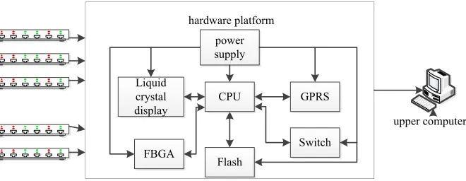
responsible for converting the optical signal into an electrical signal, which is the key to the entire system. The RS-485 communication module is designed to upload data to the upper computer faster, more stably, and more accurately, and to receive the upper computer commands more quickly. The liquid crystal display module is a human-ma-chine interface, which can visually display the specific value of the feature quantity in the slope monitoring and can intuitively reflect the stability of the slope. The Flash module is used to store the necessary parameters of the sensor and other parameters required by the system's peripherals. The button module is more convenient for the user to fully understand the current detection status of each sensor. The overall frame of the fiber grating slope detection system is shown in Figure 1.
Fig. 1. Overall block diagram of grating slope detection system
The FBG sensor mainly measures three characteristic quantities: osmotic pressure, crack, and angle. The optical signal passes through the sensor to the hardware platform, and the hardware platform receives the optical signal for processing. The change of the feature quantity is displayed on the liquid crystal display of the hardware platform, and it is transmitted to the host computer through RS-485 communication or GPRS. When the host computer receives this information, it is displayed on the display side.
3.2 The principle of fiber bragg grating sensing
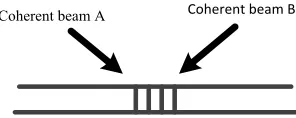
Fiber gratings are made with a special technique on the fiber to form a row of mutu-ally parallel, equmutu-ally spaced grids. In 1978, Hill et al. first discovered that after the erroneous elements are mixed in the light, the laser will cause interference in the fiber, and the refractive index of the fiber changes along the axial direction. This is the first time in the world that fiber Bragg gratings have emerged. Although fiber gratings have emerged at that time, it has not attracted attention due to its difficulty in fabrication and poor repeatability. Until 10 years later, when two interference ultraviolet beams are used to cause interference fringes to enter from the fiber side, a permanent refractive index change will be generated in the interior. Figure 2 is a schematic diagram of fab-ricating an optical fiber grating.
power supply
Flash Liquid
crystal display
FBGA
GPRS
Switch hardware platform
Fig. 2. Schematic diagram of fabricating an optical fiber grating
Among them,
. (1)
A is the fiber modulation period, is the wavelength of the UV coherent beam, and θ is the angle between the coherent beams. From equation (1), it can be concluded that when the coherent beam wavelength and the angle θ are different, the refractive in-dex modulation period of the produced fiber grating will be correspondingly different. Fiber gratings usually change the refractive index of a part of the core of the fiber and have a periodic modulation. The range of change is only between 10-3 and 10-5, so it
only changes a small spectrum of the light source, and it becomes Light wave mirror. This invention makes the fiber grating gradually known to the world, and its develop-ment is getting faster and faster, and has many advantages, such as small volume, strong anti-electromagnetic interference capability, strong series multiplexing capability, good durability and strong corrosion resistance.
3.3 Fiber bragg grating demodulation principle
The FBG sensor has strong anti-electromagnetic drying capability, but it also needs to convert the optical signal into an electrical signal in the terminal link to facilitate subsequent signal analysis and processing. Fiber bragg grating demodulation technol-ogy is the most core technoltechnol-ogy in fiber bragg grating sensing system. The accuracy of demodulation directly affects the accuracy of the whole system, and its stability also determines the overall stability of the system. Fiber grating demodulation methods are various. According to different types of demodulated signals, the demodulation nology is divided into frequency demodulation technology, phase demodulation tech-nology, intensity demodulation technology and wavelength demodulation technology. The matched grating filtering method is to find a grating that can totally reflect or transmit reflected light. Therefore, the matched grating filter method can be divided into two types, reflective and transmissive. Figure 3 shows a schematic diagram of the working principle of the transmissive filtering method. The PTZ piezoelectric ceramic device in the figure can adjust the wavelength of the matching grating according to the different voltage values.
Coherent beam A Coherent beam B
) 2 sin(
2 q
l
=
A
l
Fig. 3. Transmissive matched grating filter method
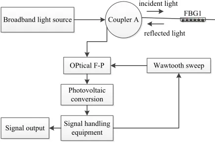
The tunable fiber F-P filtering method demodulates the signal by the property that different lengths of the F-P cavity correspond to different wavelengths. As shown in Figure 4, the sensor reflected light enters the fiber F-P filter through the coupler and adjusts the cavity length to change whether the reflected light can pass through the filter. When the reflection spectrum and the transmission spectrum of the filter are same, the signal outputs maximum power.
Fig. 4. Tunable fiber F-P filter method
Edge filter method is a kind of linear demodulation system, which uses the linear characteristics of some filters to combine the power of light with the offset of the optical wavelength. The amount of change in power corresponds to the amount of wavelength change. The filtering method can be expressed as:
. (2)
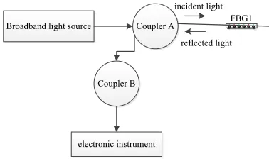
In the equation, K is the slope of the edge filter, A is the wavelength in the reflected light, is the wavelength of the light after the reflected light passes through the edge filter, and is the amount of power change. Figure 5 is a working principle diagram of the edge filter method demodulation system. The light generated by the light source
Broadband light source Coupler A
Coupler B
FBG1 incident light
reflected light
Broadband light source Coupler A FBG1
incident light
reflected light
OPtical F-P
Photovoltaic conversion
Wawtooth sweep
Signal handling equipment Signal output
)
(
)
(
K
BP
l
=
l
-
l
l
B
enters the FBG sensor to generate reflected light after passing through the coupling device A; after the coupler A enters the coupler B, it is divided into two. One is first detected by the edge filter and then its power is detected, and the other is directly de-tected its power. From these two paths of light, the amount of change in power after passing through the edge filter can be obtained. From formula (2), the offset of the wavelength can be obtained, thus achieving wavelength demodulation.
Fig. 5. Edge filter method
4
Software and hardware design of fiber grating slope detection
system
In a complete system, the sensor receives external information and feels a series of sensitive changes from the outside world. The hardware system summarizes all the in-formation, processes all the information it feels, and feeds back the processed useful information to other parts. Therefore, the design of the hardware system must be based on stability and reasonableness. A reasonable and stable hardware system can provide a perfect platform for the construction of the operating system and the operation of the application program. The hardware system of the system is mainly composed of a power supply module, a core control module, a key display module, an optical switch, a demodulator module, an RS-485 communication module, and a FLASH module. The following will be a detailed description of the hardware system divided into several parts based on the principle of modularization.
Fig. 6. Hardware circuit module diagram
l
Broadband light source Coupler A FBG1 incident light
reflected light
Coupler B
electronic instrument
power module
RS-485
LCD module
FBGA module
Master controller
GPRS module
SWITCH module
The design of the power module is based on the voltage information, power level, and electromagnetic interference required by the chip. The GPRS used by the system requires 5VCD voltage, while the MCU requires 3.3VDC voltage. The user requires the system to use the national standard AC power as the power source. Therefore, it is necessary to convert 220VAC to 5VDC and 3.3VDC and take into account the power problem and the use of dual outputs. Between AC to DC, EMC filtering needs to be considered. EMC means that useful information and disturbance information can coex-ist without destroying the information contained in the signal. The purpose of exploring electromagnetic compatibility is mainly to improve the ability of electrical devices to operate normally under various magnetic field environments, and to investigate the principles and prevention methods of electromagnetic waves that pose a hazard to pro-duction, life and people's health. The design of electromagnetic compatibility for the system should be carried out as early as possible so that the problem can be solved early and the corresponding cost is less and the effect may be better. After filtering, it is necessary to convert 220VAC to 5VCD voltage. In order to more accurately and stably perform the voltage conversion, the EMC filter FC-LXID3 produced by MORNSUN and the AC/DC modules LH25-10B05ER2 are used to complete the 220VAV to 5VDC conversion task. FC-LXID2 input voltage is 85-305VDC. Its operating temperature adaptability is strong and the size is small. It is suitable for PCB mounting. LH25-10B05ER2 is a special switching power supply for power system. The input voltage is between 85-264VAC. It has high efficiency, high reliability, safety isolation, output short-circuit, over-current, over-temperature protection, etc. The surge performance meets the actual national standards. It can also meet PBC installation requirements. FC-LXID2 and LH25-10B05ER2 plus the corresponding peripheral circuits such as fuses, resistors, capacitors, etc. can complete the conversion from 220VAC to 5VDC.
The system software design of the host computer is based on the customer's needs, and it strives to be simple and direct. It can complete the required functions of the sys-tem. The fiber grating slope monitoring system should have the following functions: system management, real-time information monitoring, historical data query, sensor data information and other major functions.
The main content of system management is to select the demodulator serial port and database IP modification. After the system software is turned on, it must have the cor-rect serial port selection so that the system can receive data. The database IP can be linked to the database after it has been modified.
The real-time information monitoring module is the main function of the system. It is a display of the three main features of the system—osmotic pressure, angle, and cracks. Accurately displaying these three feature quantities will enable the user to grasp the current slope conditions in order to make corresponding adjustments.
The system has a historical data query function. All sensor numbers are on the right of the historical data query. Click the corresponding number to select the sensor. Simi-larly, the corresponding sensor number can be filled in the blank at the top, and the query time can be selected below the sensor number. When the sensor and time are selected, after the query is started, the mouse is placed on the curve, and the value and time of the current mouse position are displayed below the mouse.
For each sensor, its real-time curves, historical curves, and properties can all be se-lected for observation here. The historical curve and the historical data query function are same, and the real-time curve is the curve of the current sensor. Similarly, when the real-time curve is displayed, the value of the current mouse position is also displayed below the mouse. The attribute is the property of the sensor. For example, the ten roads in the figure can be changed to the actual installation position of the sensor in the at-tribute.
5
System testing and analysis
5.1 The performance test of fiber bragg grating angle sensor
The most fundamental criterion for determining the quality of a sensor is accuracy. If the accuracy of the sensor is poor, other aspects are even better and can’t be used normally. Therefore, the sensor designed by this system must be calibrated before the engineering test to observe its performance, repeatability and linearity. These are the things that must be noticed in the calibration process.
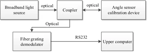
The angle sensor can be fixed on the rod. When the beam is placed at a certain known angle, the hammer of the sensor is always downward due to gravity, which will cause the equal-strength cantilever beams in the sensor to produce shape changes, thus caus-ing changes in the fiber gratcaus-ing. Figure 7 is a schematic diagram of the calibration sys-tem.
Fig. 7. Schematic diagram of the calibration system
5.2 The performance test of fiber grating crack sensor
The performance test system of the fiber grating crack sensor is almost same as that of the angle sensor test system, and only the calibration device is different. The iron pieces A, B are fixed on the base, and one end of the sensor is connected to the iron
Broadband light
source Coupler calibration deviceAngle sensor
Fiber grating
demodulator Upper computer optical optical
Optical
piece B by the wire, and the other end is fixed on the movable rotating column. Test the center wavelength of the sensor without any tension, and then install the sensor as written. Make sure that there is no force on the sensor and the center wavelength is the same as the initial state.
In the performance test process, the test is conducted without any pulling force. At different temperatures, multiple measurements are taken to obtain the average value. Table 1 shows the variation data of the temperature compensation grating and the meas-urement grating.
Table1. Variation data of the center wavelength in the temperature compensation grating and the measurement grating
Temperature(℃) 35 40 45 50 55
Removing grating 1530.242 1530.295 1530.344 1530.392 1530.445
Measuring grating 1535.181 1535.233 1535.279 1535.331 153.383
The length of an iron ore tailings dump is about 1,000 meters. And a bridge is built on one side, which is a large item piled up. The dam is not equipped with an automatic monitoring system. There are 10 observation wells and 4 displacement monitoring points for artificial monitoring facilities. All of them are judged by artificial eye obser-vation.
There will be cracks on the surface of the dam, and cracks need to be monitored in real time. According to the data, when the dam body crack exceeds 50mm, there is a huge potential safety hazard in the dam body. For the inclination of the dam body, that is, the body firmness angle, real-time monitoring is needed. When the inclination angle of the dam body reaches a certain amount, gravity will be greater than the interaction force between the dam body, which will cause the dam body to collapse and cause tragedy. Because moisture will continuously seep into the dam, when the water reaches a certain level, the dam may be damaged due to the existence of water pressure, causing flooding. Therefore, it is necessary to monitor the infiltration pressure of the dam in real time. For the above three key factors affecting the dam body, it is required that the measuring elements have high sensitivity and high degree of automation, and the safety factor of the dam body can be predicted by analyzing the data in advance. The system can analyze the monitoring data through long-term monitoring and current operation to determine whether the current tailings warehouse is operating safely.
6
Conclusion
With the rapid advancement of science and technology, the stability of the mining tailings, highways, and railways affects people's normal lives at all times. In some places, due to the unstable slope, the damage caused by the landslides and the burst of the reservoir will be inestimable. Therefore, slope monitoring has become an indispen-sable part of many current engineering safety operations. The slope monitoring system based on FBG sensor is designed in accordance with the development of science and technology and people's needs.
The most advanced FBG sensors are generally used, which have strong anti-electro-magnetic interference capability, low long-distance transmission loss, long service life, simplicity, convenience, easy installation and maintenance, multi-point detection, and high accuracy. It is increasingly important in slope monitoring. The STM32F205 is used as the MCU on hardware, and the 32-bit RISC computer based on the ARM Cor-tex-M3 can work normally at 120MHz frequency. With rich peripheral interfaces, the chip can drive more peripherals and can build a very perfect development platform. The upper computer software is written in C++ language. The grammar structure is explicit. The processing speed is the fastest. It is very flexible and powerful. The host computer develops the supporting software based on VS2010 and realizes real-time communica-tion with the lower computer. At the same time, it combines with the SQL server2008 database to access the data in real time, thus completing the data analysis, storage and display.
7
References
[1]Naranjo, P. G., Shojafar, M., Mostafaei, H., Pooranian, Z., & Baccarelli, E. (2017). P-sep: a prolong stable election routing algorithm for energy-limited heterogeneous fog-supported wireless sensor networks. Journal of Supercomputing, 73(2): 1-23. https://doi.org/10.1007/ s11227-016-1785-9
[2]Li, X., Tao, X., & Li, N. (2016). Energy-efficient cooperative mimo-based random walk routing for wireless sensor networks. IEEE Communications Letters, 20(11): 2280-2283.
https://doi.org/10.1109/LCOMM.2016.2599183
[3]Yuvaraja, M., & Sabrigiriraj, M. (2017). Fault detection and recovery scheme for rout-ing and lifetime enhancement in wsn. Wireless Networks, 23(1): 1-11. https://doi.org/10.1007/ s11276-015-1141-7
[4]Zhu, Y. H., Qiu, S., Chi, K., & Fang, Y. (2017). Latency aware ipv6 packet delivery scheme over ieee 802.15.4 based battery-free wireless sensor networks. IEEE Transac-tions on Mo-bile Computing, 16(6): 1691-1704. https://doi.org/10.1109/TMC.2016.2601906
[5]Thang, V. C., & Tao, N. V. (2016). A performance evaluation of improved ipv6 routing protocol for wireless sensor networks, 8(12): 18-25.
[6]Ferng, H. W., & Khoa, N. M. (2016). On security of wireless sensor networks: a data au-thentication protocol using digital signature. Wireless Networks, 23(4): 1-19.
[8]Gomez, C., Paradells, J., Bormann, C., & Crowcroft, J. (2017). From 6lowpan to 6lo: ex-panding the universe of ipv6-supported technologies for the internet of things. IEEE Com-munications Magazine, 55(12): 148-155. https://doi.org/10.1109/MCOM.2017.1600534
[9]Zhu, Y. H., Chi, K., Tian, X., & Leung, V. C. M. (2016). Network coding-based reliable ipv6 packet delivery over ieee 802.15.4 wireless personal area networks. IEEE Trans-actions on Vehicular Technology, 65(4): 2219-2230. https://doi.org/10.1109/TVT.2015.2419082
8
Authors
Lin Huang works at the Institute of Geotechnical Engineering, Xi’an University of Technology, Xi’an, China.
Fengyin Liu works at the Institute of Geotechnical Engineering, Xi’an University of Technology, Xi’an, China.
Jun Li works at the Institute of Geotechnical Engineering, Xi’an University of Tech-nology, Xi’an, China.