Using Constrained Multi-Optimization in
Design of Composite for Filament Wound
High Pressure Vessels
Dijana Cvetkoska#1, Igor Dimovski#2, Samoil Samak#3, Mirjana Trompeska#4, Vladimir Dukovski#5
#12345
Institute for Advanced Composites and Robotics Krusevski pat bb, Prilep, Macedonia
Abstract
Composites as multiphase materials offer the possibility to influence their properties or to add new functionalities by a proper choice and combination of the different phases. In addition to get best properties for the composite design numerous calculations for different combination of the fibers winding angles should be done. This paper targets the design of a composite laminate structure used for production of high pressure vessel. The application developed in this research manages to design a composite with most effective elastic modules, in a time shorter than the usual composite designing time, taking into account filament winding process, materials price as well as the purpose of the final product. This application uses a database of available materials in order to point out which combination creates a pressure vessel of cheaper composite material with the best strength, bulk modulus and load level of failure.
Keywords — composite design; composite material; database of materials; multi-objective optimization; high pressure vessel
I. INTRODUCTION
Pressure vessels are closed containers designed to hold gases or liquids at a pressure different from the ambient pressure. These are important because many liquids and gases must be stored under high pressure. In the industry these containers are designed to operate safely at a specific pressure and temperature. Theoretically a pressure vessel can be almost of any shape, but shapes made of sections of spheres, cylinders and cones are most common used. The design of the vessel shape is an optimization process by itself which is presented in several research articles systematized by Saidpatil et al. [1] and Hassan et al. [2]. The basics of the optimization in the composite design are systematically discussed by Miravete in [3]. He provides a survey of various design methodologies.
However, to achieve the requirements of today‟s industry in terms of weight and durability the vessel made of homogenous light weight material should be strengthened with fiber-reinforced composite material. A major advantage of fiber-reinforced composite material is the large number of design variables available to the designer. In 1993 Adali et al. [4] addressed the problem of optimally designing symmetrically laminated composite pressure vessels using fiber orientation and wall thickness as design variables. Here they separated the problem into two stages: the effect of fiber orientation on the burst pressure and the weight of the shell taking the fiber angle and the wall thickness as variables. As the internal pressure increase, it was shown that the results for the second stage problem, approach to the results of the first stage. Taking this into account this paper focuses on the fiber orientation as main optimization variable. Later in 2012, Yarrapragada et al. [5] suggested an analytical model for prediction of optimum fiber orientation for given layer thickness.
As mentioned above fiber-reinforced composite material gives the designer a freedom of large number of variables that affect the final product in a different way. In practice, the design of a composite structure often requires maximization or minimization of multiple, often conflicting objectives. In regards of laminate design Pelletier and Vel in [6] described the multi-objective optimization of fiber reinforced composite materials for strength, stiffness and minimum mass via the layerwise tailoring of fiber orientations and fiber volume fraction.
will have a cheaper laminate composed of a lamina with best strength that provide a maximal resistance to compression.
The multi-optimization used in this paper is constrained with the restrictions arising from the filament winding process. So, the result is a set of angles that ensures that each angle will be in range that could be laid up during the winding process, each layer of the laminate wind with these angles will be completely closed and the produced high-pressure vessel will have twice larger pressure in the cylindrical parts than in the elliptical extensions.
II. METHODOLOGY
During this research project it has been developed an algorithm that will work with a base of available (user defined) materials and obtain the most appropriate combination of materials to be used. Working with base of materials leads to more theoretical tests which decreases the design and testing costs, accelerates results‟ calculation and material selection, and shortens design time.
The objective of the research is finding the optimal values and order of the angles for composite design, based on the criteria described in 2.2.2 in intension to get best micro-macro mechanical properties [7]-[9] of the manufactured composite. Micromechanics help us understand interactions between different constituents of composite on a microscopic scale (failure mechanisms in fibers and in matrix, interface failure mechanisms etc.). Macromechanical analysis looks at the composite as a homogenous material and material properties are assumed to be an averaged value of those of constituent material. In intension to provide the optimal angle values and order, it has been decided that optimization is the best method to be used.
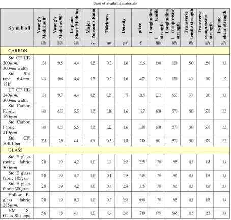
TABLE I Base of available materials
S y m b o l
You ng’s Modulu s 0° You ng’s Modulu s 90° In -plan e Sh ear Modulu s Maj or Poi ss on’s Ratio Th ic kn ess Dens ity pric e Lon gitud ina l te ns ile stre ngth Lon gitud ina l com pr essive stre ngth Transverse te ns il e str ength Transverse com pressive stre
ngth In-plan
e
sh
ear
stre
ngth
E1 (GPa) E2 (GPa) G12 (GPa) v12 mm g/cm3 € MPa MPa MPa MPa MPa
CARBON Std CF UD 300gsm, 300mm width
138 9,5 4,4 0,25 0,3 1,6 20,6 1500 1200 50 250 110,3
Std Slit tape 6.4mm, 12K
143,4 10,6 4,4 0,25 0,2 1,6 46,27 2159 1330 40 300 112,7
HT CF UD 240gsm, 300mm width
131 9,7 4,4 0,25 0,25 1,77 21,5 2212 953 30 200 110,3
Std Carbon Fabric, 160gsm
140,4 6,35 5,5 0,05 0,16 1,6 19,7 600 570 600 570 115,2
Std Carbon Fabric, 210gsm
140,4 6,35 5,5 0,05 0,22 1,6 13,18 600 570 600 570 115,2
Std. CF,
50K fiber 235 7,9 4,4 0,39 0,5 1,8 20 600 570 600 570 115,2 GLASS
Std E glass roving fabric 300gsm
20 19 4,2 0,13 0,3 2,58 2,25 1795 965 61,5 155 110,4
Std E glass
fabric 105gsm 20 19 4,2 0,13 0,1 2,58 2,45 1795 965 61,5 155 110,4
Std E glass
fabric 300gsm 20 19 4,2 0,13 0,4 2,58 3,15 1795 965 61,5 155 110,4
Hollow E-glass fabric 285gsm,
6.4mm
BASALT Std Basalt Fabric 115gsm, width 1270mm
88 18 4,2 0,26 0,1 2,7 6,55 4840 1500 60 530 111,2
Std Basalt Fabric 220gsm, width 1500mm
88 18 4,2 0,26 0,2 2,7 5,25 4840 1500 60 530 111,2
The experiments are done on High Performance Computing (HPC) system from Arctur which leading service provider in the field of supercomputing in South Eastern Europe is [10]. This means that all of the algorithms used are adopted to work in parallel process. After a thorough search for the software, GNU Octave [11]-[12] and Open MPI Package were chosen, since it‟s free software, although the same (maybe even better) work can be done in MATLAB. For the optimization method genetic algorithm for multi-objective optimization [13]-[14] is used.
At the begging a lot of theoretical tests were performed, and the results were compared with some other available results obtained from the research projects in the Institute for Advanced Composite and Robotics. Furthermore, in order to verify the results optimization-based result were compared with other composite design software [15].
In order to get results that integrate all parameters (distribution of forces inside the cylinder, composite structure properties, filament winding process) numerous calculations need to be performed, as the number of control points in the initial generation for the optimization process, directly influences the accuracy and precision of the calculations. Technical benefits from this model will reflect on complex calculations of the deformations of the high-pressure vessels using different kind of materials for the composite design (regarding number of broken fibers, mandrel volume variations, and work pressure estimates) that precede tests of the final product.
A. Variables
Input variables for the software developed with this research are database of materials, number of layers for the composite design, number of materials from the database that will be used in one material design and optimization algorithm control variables. Example of the database of materials with their properties is given in Tab. 1, [15].
The output is .txt file with a set of optimal angles that minimizes one or all objective functions and material combination for each of the angles combination. With the multi-objective optimization, a set of optimal solutions which need to be further examined is obtained. The final step is the choice of the best solution according to the objective values.
B. Mathematical Model 1) Problem Definition
High pressure vessel has two parts: a plastic liner that is wrapped with composite material, Fig. 1. The liner is just a mold (it‟s very poorly resistant) and what gives a hardness of the vessel is the composite part. The goal is designing a composite material that will have „best‟ micro-macro mechanical properties for a certain purpose. A composite laminate is a material which consists of two or more distinct layers with specific structure assembled to achieve certain physical properties. The layers can be of different thicknesses, their inner fibers‟ orientation may differ, and they may involve different materials.
In the classical elasticity theory, the composite is modelled using 2 (two)-dimensional plane approximation of the layers, and the forces are considered in the mid-surface.
Fig. 1 Cross section of the composite vessel
2) Objective Functions
The main property describing each material is the material moduli of elasticity. There are several modules of elasticity describing the material. Each of them presents the ratio of stress applied to a body to the resulting strain within the elastic limit. According to the simple definition of the modulus of elasticity for homogenous material, it is a number that measures an object of substance‟s resistance to being deformed elastically when a force is applied to it. Now the materials that are very strong have very high modulus of elasticity because it is needed to apply a large amount of force in order to obtain very small amount of deformation [16]. When non-homogenous material as composite is considered, the ratio between the stress applied to the resulting strain is different in different directions. For example, when stress is applied in fibers direction (longitudinal stress) the material is more resistant then if the stress is applied in transversal direction. That‟s why the focus is put on the shear modulus of elasticity since it combines both (longitudinal and transversal) stresses.
1 2 1 2
1 2 2 1 2 1
E E G
(1)
In Eq. (1) E1 stands for longitudinal and E2 for transversal stress, and are Poisson‟s ratios for the material.
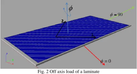
Shear modulus describe the material resistance when the force is applied in some other (different than fibers) direction, Fig. 2.
Fig. 2 Off axis load of a laminate
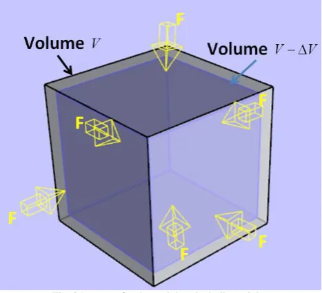
Next modulus that is chosen to be maximized in order to obtain more hardness material is Bulk modulus – the ratio of the stress in the body to the body‟s fractional decrease in volume [9], [16]. This modulus is used since it adds another dimension in the formulas for micro-macro mechanical properties, Fig. 3.
3
1 2 3
3
1 2 3 1 2 3 3 1 2
E E E K
(2)
In Eq. (2) E1, E2 and E3 are Young‟s moduli, ν12, ν31 and ν23 are Poisson‟s ratios.
Fig. 3 Pressure for determining the bulk modulus
When a ply fails, it may have cracks parallel to the fibers. This ply is still capable of taking load parallel to the fibers. Here, the cracked ply can be replaced by a hypothetical ply that has no transverse stiffness, transverse tensile strength, and shear strength. The longitudinal modulus and strength remain unchanged.
When a ply fails, fully discount the ply and replace the ply of near zero stiffness and strength. Near zero values avoid singularities in stiffness and compliance matrices.
The procedure for finding the successive loads between first ply failure and last ply failure given below follows the fully discounted method:
a) Given the mechanical loads, apply loads in the same ratio as the applied loads. b) Use laminate analysis to find the mid-plane strains and curvatures.
c) Find the local stresses and strains in each ply under the assumed load.
d) Use the ply-by-ply stresses and strains in ply failure theories. In this algorithm implementation of Tsai-Wu failure theory [7] is applied. According to this theory, the quadratic equation.
2 2
1 1 2 2 6 1 2 1 1 1 ... 2 2 2 2 1 2 1 2 1
H H H H H H (3) is solved in order to obtain the strength ratio. In (3) the components H1, H2, H6, H11, H12, H22 are found
using the five strength parameters of a unidirectional lamina [7], σi stands for the tensile stress in i
direction and τ12 is the shear stress.
Multiplying the strength ratio SR by the applied load gives the load level of the failure of the first ply. This load is called the first ply failure load.
; ;
x x y y x y x y
N C N S R N C N S R N C N S R (4)
where Nx and Ny are normal forces per unit length and Nxy is shear force per unit length.
e) Degrade fully the stiffness of damaged ply or plies. Apply the actual load level of previous failure. f) Go to step b) to find the strength ratio in the undamaged plies:
f1) If the strength ratio is more than one, multiply the strength ratio to the applied load. To give the load level of the next ply failure and go to step b).
f2) If the strength ratio is less than one, degrade the stiffness and strength properties of all the damaged plies and go to step e).
g) Repeat the preceding steps until all the plies in the laminate have failed. The load at which all the plies in the laminate have failed is called the last ply failure.
The objective of the optimization is to maximize all the strength ratios for all laminas in the laminate.
3) Constraint Functions
Since designed composite should be used in filament winding production of high pressure vessels, the optimization process should be done according to some constraints including the distribution of forces in high pressure vessels and filament winding process itself.
According to the distribution of forces in high pressure vessels it can be shown that the pressure on the vessel cylindrical part is twice larger than the pressure in the elliptical extensions. That‟s the reason one of the constraints is that the tensile stress σ1 is twice larger than the stress σ2 in longitudinal direction, Eq. (5). Since
the experiment aims the design of composite structure for high pressure vessel this is the first constraint function.
1 2 2
(5) Next, since filament winding technology is used for the manufacturing, it is important to know winding technology constraints. Here, some of these constraints are used:
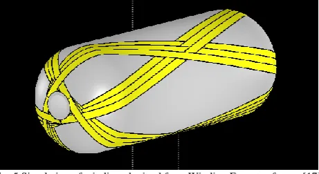
1. For the vessel to be completely closed for each layer with one angle there should be another layer with opposite angle, Fig. 5. In this kind of technology those layers are usually pared in. So, the next equality constraint is:
1 0
i i
(6) for each adjacent pair of layers. θi and θi+1 in Eq. (6) are the optimization variables (composite design
angles).
Fig. 5 Simulation of winding obtained from Winding Expert software [17]
C. Optimization Method
Several optimization methods were reviewed. At the beginning, Sequential Quadratic Programming (SQP) method was used, as already available one in Octave [11].
The problem description:
Minimize f(x)
Over x n
Subject to h(x) = 0 ( ) 0
g x
where f : n is the objective function, the functions h: n m and g : n pdescribe the equality and inequality constraints. SQP is an iterative procedure which models the nonlinear optimization problems (NLP) for a given iterate , 0
k
x k by a Quadratic Programming (QP) sub-problem, solves that QP
sub-problem, and then uses the solution to construct a new iterate x^(k+1),k∈N_0. This construction is done in such a way that the sequence
0
k k
x
converges to a local minimum x
*
. In this sense, the NLP resembles the
Newton and quasi-Newton methods for the numerical solution of nonlinear algebraic systems of equations. However, the presence of constraints renders both the analysis and the implementation of SQP methods much more complicated [12], [18].
However, there are several objective functions, but „SQP‟ method minimizes only one of these. That‟s why multi-objective optimization algorithm given by Povalej [13] is used.
As mentioned before the main advantage of the multi-objective optimization is that one can optimize more objective functions fi(x) at once. However, one should be careful to optimize conflicting objective functions that are constrained with the same constraint functions gp (x) and hp (x).
1 2
m i n / m a x , , ...,
0 0
m
n
p p
f x f x f x
x g x h x
(7)
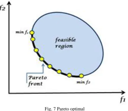
After several iterations a set of non-dominated points called Pareto optimal front [13]-[14] is received and this set represents the solution to the problem, Fig 7.
Fig. 7 Pareto optimal
For multi-objective optimization the parallel version of DEMO (Differential Evolution for Multi-objective Optimization) algorithm is used. The algorithm is a variant of genetic algorithms and in each iteration, it finds the set of non-dominated points. Here, the main term is domination of the evaluation space. The point x dominates y if x is not worse in all objectives, but it is better in at least one objective.
III.TESTINGANDRESULTS
material that is to be used for the composite. Usually, there is a database of most widely used materials from which the designer should chose the most appropriate ones, by testing different material combinations. Testing procedure can be quite time consuming for the designer of the composite. Therefore, an algorithm which makes all material combinations in a given database is applied, for a composite material with N (user input) layers where K (user input) materials will be used. This algorithm has complexity of order O(M), where M is the number of materials in the database.
Fig. 8 Pareto optimal solution obtained from the tests
Fig. 8 shows multi-objective optimization used to find optimal angles and combinations of materials where different objectives are optimized simultaneously. Here, shear modulus, bulk modulus and ply-by-ply failure criteria were optimized. Sometimes, when several materials are available for testing, material price as one of the objective functions could be added. Clear results on the 3D graph cannot be seen, but if the results are showed in 2D (Fig. 9 shows bulk and failure criteria) one can see a picture of the Pareto optimal solution. So, from the entire set of non-dominated points (since the solution of the problem is set of combinations - not just one combination) one can choose which solution best fit in.
As a result, from the previous example a set of 38 combinations is obtained from which, according to the values of the objective functions, the most appropriate ones for the specified needs are chosen. Since the goal is to design a composite for high pressure vessels, compared to the internal pressure, external pressure can be neglected. That‟s why from the optimized set of combinations only 5 were chosen for further testing (the ones with low bulk modulus but high value for the failure criterion). Table 2 and Table 3 show two of the chosen results.
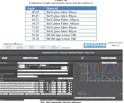
Before starting the physical testing for analysis of the designed composite Hoffmann Engineering - Composite Oracle [15] software was used to calculate theoretical Burst pressure for the designed composite, Fig 10. This software is used to check designed composite ply failure using some other criteria, different than Tsai-Wu that is used during the optimization process. The point is that using Composite Oracle [14] the designer must know fiber angles before calculating composite material properties unlike the approach in this paper when one initial guess is enough in order to obtain material with most effective elastic modules.
TABLE II
Combination of angles and materials chosen from the solution set
Angle Material
-90,00 Std E glass fabric 80 gsm
90,00 Std E glass fabric 80 gsm
62,82 Std Basalt Fabric 220gsm width 1270mm
-62,82 Std Basalt Fabric 220gsm width 1270mm
32,48 Std E glass fabric 80 gsm
-32,48 Std E glass fabric 80 gsm
-29,17 Hollow E-glass fabric 285gsm
29,17 Hollow E-glass fabric 285gsm
TABLE III
Combination of angles and materials chosen from the solution set
Angle Material
-89,45 Std E glass fabric 80gsm
89.45 Std E glass fabric 80gsm
44.23 Std Carbon Fabric 160gsm
-44.23 Std Carbon Fabric 160gsm
71.65 Std E glass fabric 80gsm
-71.65 Std E glass fabric 80gsm
54.36 IM Slit tape 6.4mm 24K -54.36 IM Slit tape 6.4mm 24K
Fig. 10 Composite Oracle software
IV.DISCUSSIONANDCONCLUDINGREMARKS
As mentioned above, the output from the algorithm subject to this experiment is a set of composite designs that need to be further processed in order to choose the most appropriate one. Further processing includes a selection of the design that fits the environment for which it is intended to be used, sometimes last ply failure may be the most important criteria, sometimes it‟s the cost (forexample from all of the obtained results simply select the cheapest). Often, physical tests should be performed for most of the provided results because particularly in composite materials theoretical results must be practically verified.
Although this paper has been specifically focused on production of composite high-pressure vessels, acquired experience and output can also be applied to different shapes of composite end products as well.
REFERENCES
[1] Saidpatil, V. V.; Thakare, A. S. “Design & Weight Optimization of Pressure Vessel Due to Thickness Using Finite Element Analysis.” International Journal of Emerging Engineering Research and Technology, 2, 3(2014), pp. 1-8
[2] Hassan, S.; Kumar, K.; Raj, C. D.; Sridhar, K. “Design and optimisation of pressure vessel using metaheuristic approach.” Applied Mechanics and Materials, 465 (2014), pp. 401-406. DOI: 10.4028/www.scientific.net/AMM.465-466.
[4] Adali, S.; Summers, E. B.; Verijenko, V. E. “Optimisation of laminated cylindrical pressure vessels under strength criterion.” Composite structures, 25,1( 1993), pp. 305-312. DOI: 10.1016/0263-8223(93)90177-R
[5] Kss, R. Y.; Mohan, R. K.; Kiran, B. V. “Composite pressure vessels.” International Journal of Research in Engineering and Technology, 1, 4(2002), pp. 597-618
[6] Pelletier, J. L.; Vel, S. S. “Multi-objective optimization of fiber reinforced composite laminates for strength, stiffness and minimal mass.” Computers & structures, 84, 29(2006), pp. 2065-2080. DOI: 10.1016/j.compstruc.2006.06.001
[7] Kaw, A. K. Mechanics of composite materials. 2nd. ed. CRC press, Boca Raton, 2006
[8] Voyiadjis, G. Z.; Kattan, P. I. “Mechanics of composite materials with MATLAB.” Springer - Verlag Berlin Heidelberg, 2005. DOI: 10.1007/3-540-27710-2
[9] Composites Design and Manufacture. Plymouth University [Online]: http://www.tech.plym.ac.uk/sme/MATS324/MATS324A2%20E-G-nu.htm#K (18.12.2014).
[10] Supercomputing service provider, Arctur web universe [Online]: https://www.arctur.si/references/web_sites/2015020613122861/ (03.04.2016)
[11] Sharma, N.; Gobbert, M. K. A comparative evaluation of Matlab, Octave, FreeMat, and Scilab for research and teaching. ITAM. [Online]: http://ciep.itam.mx/~rtorres/progdin/comparative-evaluation-of-matlab-octave-scilab-freemat.pdf (08.03.2016)
[12] Eaton, J. W.; Bateman, D.; Hauberg, S.; Wehbring, R. GNU Octave version 4.0.0 manual: a highlevel interactive language for numerical computations. GNU Octave. URL: http://www.gnu.org/software/octave/doc/v4.0.1/ (05.06.2015).
[13] Povalej, Ž. “Metode smeri spusta v večkriterijski optimizaciji.(2013)”. (Doctoral dissertation Univerza Ljubljani, Ž. Povalej). [14] Robič, T.; Filipič, B. DEMO: “Differential evolution for multiobjective optimization.” Evolutionary multi-criterion optimization
3410(2005). pp. 520-533. DOI: 10.1007/978-3-540-31880-4_36
[15] Composite Oracle, [Online]: http://www.composite-oracle.com/main.asp?q=13 (07.06.2015).
[16] Groover, M. P. “Fundamentals of modern manufacturing: materials processes, and systems.” John Wiley & Sons, Hoboken, 2007. [17] Design consulting company, filament winding software. Mikrosam [Online]:
http://www.mikrosam.com/new/article/en/winding-expert/ (03.04.2016)