Test results for a capacitance-based corrosion sensor
Helena K. Twigg Marc Molinari
Southampton Solent University, Hampshire, SO14 0YN, United Kingdom 02382016514
Abstract
This paper describes a way of monitoring for steel surface corrosion in its early stages, before it becomes structurally dangerous. It is envisaged that the presented technique is used repeatedly across the surface of a large structure to monitor for structural danger. This widespread monitoring could be achieved by means of a distributed wireless sensor network, with each sensor reporting to a base station which then checks for indications of corrosion from sensors that are located near to each other, or that are all located on the same joint. In this way, potential structural problems can be monitored, evaluated and mitigated at an early stage.
The sensor developed in this project is small, inexpensive and has low power requirements. It is therefore suitable to be integrated into a wireless distributed sensor array which could be set up and left to monitor autonomously for corrosion without human intervention.
Current corrosion sensing technology is appraised before the theory behind a capacitive sensor to detect surface corrosion is presented. The sensor was then fabricated, and initial tests are detailed and the results discussed.
1.
Introduction
The global cost of corrosion was estimated in 2013 to be $2.5 trillion, or 3.4% of the global GDP (1). Industries that use metal structures, machinery and vessels are constantly searching both for ways of reducing the effects of corrosion, and ways of detecting it before it causes catastrophic failure. Detection often means human inspection which is time-consuming and costly and can itself endanger human life. It is also inherently unreliable because of human fallibility.
2 of the capacitor formed from the rust layer. The presence or absence of rust can therefore be sensed electronically.
1.1Current Corrosion Monitoring Technology
Because of the importance to the global economy, there are many corrosion detection technologies being developed at the present time, each one geared towards one particular market use of steel. Larsen (2) describes a system used increasingly in bridges in Florida,
USA, where there are over 10,000 bridges constructed using either steel reinforced or pre-stressed concrete. Her article refers to sensors that are embedded into the steel when it is manufactured. The sensors used are SAW (Surface Acoustic Wave) sensors which consist of a SAW crystalline device mounted on a tuned antenna. The SAW device also has a reflector array and a transducer deposited on the crystalline surface. The antenna receives an RF signal from an interrogating transceiver and converts the RF signal to an electrical shaped pulsed (in effect, demodulating the signal). The signal then travels across the crystal and bounces back from the reflector array. Any change in temperature, pressure or humidity will cause a shape change in the crystal due to the mechanical strain that the crystal is now under, and this will be shown as a phase change in the returned signal. The returned signal is re-modulated onto an RF pulse and this is transmitted back to the transceiver showing that the sensor has undergone some sort of shape change. With careful data analysis and signal processing, phase changes due to corrosion-induced shape changes at the crystal can be monitored. The sensor system is still at research stage but shows a great deal of promise as a corrosion sensor for internal steel structures when the SAW sensors are embedded at the time of manufacture.
An example of using change in capacitance to monitor corrosion can be found in the research by Chen et al. (3) where it was found that a capacitive sensor constructed from the same material as that being monitored for corrosion would reliably increase in capacitance proportionally to the amount of corrosion that had occurred. The researchers also found that the resistance of the sensor decreased proportionally to the amount of corrosion. The sensor was sacrificial as it corroded alongside the metal that it was monitoring.
3
Figure 1: Interdigitated capacitor
An interdigitated capacitor consists of two metal conductors etched on to two (usually clear) plastic substrates. The capacitance is dependent on the distance between “digits” and any interdigital dielectric substance injected between the substrates. These capacitors could also be used as corrosion sensors, because their capacitance value is affected by the distance between the digits. Usually, one side (one of the plastic substrates) is stuck to a surface to be monitored and the other floats freely close to it. If the surface moves, the capacitance changes. Applying this to corrosion monitoring, the surface expands because corrosion occurs causing a volume increase in material adjacent to the sensor. In a similar mechanism to the SAW sensors described above, a change in capacitance would occur. If this change is measured or monitored, this could be used as a sensor.
Bray et al. (5) describe a corrosion detection system using K Band (24 GHz) radar. This utilises the difference in reflectivity due to the presence or absence of corrosion products on the metal’s surface. They are primarily concerned with aluminium corrosion so the usefulness of this type of detector in sensing steel corrosion would be the subject of a whole new investigation. Nevertheless, the principle that radar reflectivity changes due to the dielectric properties of the surface is as valid for rust as it is for aluminium corrosion. K Band technology is reducing in price due to an increase in demand for Internet of Things devices. However, it is considered that at the present time the component price is still too high and the power requirements are too large to create a viable sensor system using 24 GHz technology.
Qi and Gelling (6) look at corrosion monitoring and detection state of the art in 2011 and review technologies including optical fibre, acoustic, electromagnetic, eddy current and galvanically coupled sensors. In their paper they mention a sensor based on an LC electrical circuit where phase, frequency or magnitude change of an RF signal is used to monitor progressive change of corrosion.
Yonemoto and Shida, in their two papers (7) and (8) look at the capacitive and inductive
properties of rust vs. metal surfaces and propose a dual mode sensor looking at both inductance and capacitance. They are concerned with very thin rust films (0.04µm) and are trying to minimise the effect of avalanche breakdown of the rust layer on sensor circuit switch-on. Their circuit imposes an AC current and measures the impedance that is returned, at various thicknesses of rust from 0.001 to 1 µm.
It can be seen from the above papers that capacitance alters as metal corrodes. It is intended to develop a sensor to measure the change in capacitance between corroded and uncorroded metal.
2.
Theory
4 releasing electrons, and an electronic circuit is formed. Over time (ranging from minutes to years) rust deposits are formed on the surface of the metal. Also over time, the metal itself thins as more of it turns into rust, and may buckle, no longer strong enough to perform its structural function.
The rusting process is chemically different depending on the chemistry of the steel and the environment in which rusting occurs. The rust produced is non-conductive of electricity, that is, it is an electrical insulator.
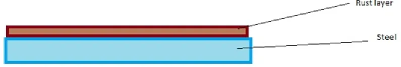
If the rust occurs uniformly across the surface of the metal (known as uniform or surface corrosion) it can be represented diagrammatically as shown in Figure 2:
Figure 2: Diagrammatic representation of surface rust on steel
By adding a conductive plate above the rust layer, an electrical capacitor is formed by the presence of two conductive layers separated by an insulator. This has the property that it can hold electrical charge across the plates because of the presence of the insulator. This is shown in Figure 3.
Figure 3: Capacitor created by the addition of a metal plate
The capacitance (a value to indicate the capacitor’s ability to hold charge) of a capacitor is given by:
𝐶 =𝜀0𝜀𝑟𝐴 𝑑
Where C = Capacitance, ε0 = permittivity of free space, εr= relative permittivity of
5
3.
Implementation
3.1Electronic Circuitry
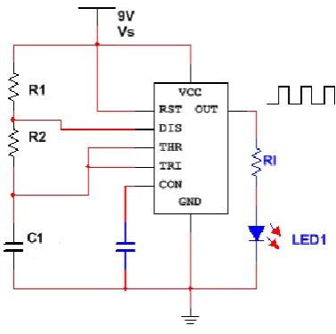
In order to monitor the capacitance of the above multi-layer structure, an electronic circuit is built based on the 555 timer. The 555 timer integrated circuit is used extensively in electronics for many purposes. It can be used in bistable, monostable and astable modes, but is used most often in the astable configuration. The circuit diagram for an astable mode 555 timer is shown in Figure 4, drawn in MultiSim™.
Figure 4: Circuit diagram for 555 timer in astable mode
In this circuit, when power is applied, the output from pin 3 is a square wave signal with a frequency dependent on the values of the resistors R1 and R2 and the capacitor C1. The
relationship between the component values and the frequency produced is given by:
𝑓 = 1
ln(2). 𝐶1. (𝑅1+ 2𝑅2)
It can be seen from the above equation that the output frequency is partially dependent on the value of the capacitor in the circuit. If this capacitor is replaced by the structure shown in Figure 2, then a corrosion sensing device would be created, that exhibits a change in output frequency depending on the dielectric properties of the rust layer that forms the capacitor C1. A 555 timer circuit in astable mode was built. The circuit diagram shown in
6
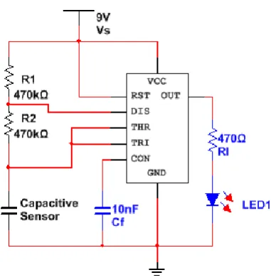
Figure 5: Circuit diagram of corrosion sensor circuit
R1 and R2 were chosen to be 470kΩ in order to make the frequency as low as possible.
The capacitive sensor, shown in the lower left of the diagram, represents the corrosion sensor, and the connection to ground is realised by having a crocodile clip-terminated flying lead connection from the negative terminal of the battery, via the circuit board, to the steel structure underlying the rust layer.
3.2Sensor Realisation
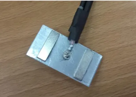
A sensor was designed as shown in Figure 6.
Figure 6: Aluminium and neodymium sensor
7
Figure 7: Practical realisation of Al and Nd sensor
The sensor shown in Figure 7 has an area of 45mm x 22mm or 0.00099m2. The
capacitance of this sensor, when it is placed on rust, can be calculated if the depth of the rust and its dielectric constant are known.
A value of 13.1 for the dielectric constant of rust was found from (9), and the thickness of the rust was found to be 0.21mm from ultrasonic NDT measurements.
The capacitance of the sensor when placed on this area of rust can be calculated as:
𝐶𝑟𝑢𝑠𝑡 =
𝜀𝑟𝑢𝑠𝑡𝜀0𝐴 𝑑
=13.1 × 8.854 × 10−12× 0.00099
0.21 × 10−3
= 5.4680 × 10⁻¹⁰𝐹
= 0.547 𝑛𝐹
This capacitance value for the sensor in the 555 timer circuit shown in Figure 5 gives an output frequency of:
𝑓 = 1
ln(2). 𝐶1. (𝑅1+ 2𝑅2)
= 1
0.693 × 5.4680 × 10−10× (3 × 470 × 103)
= 1871.23 𝐻𝑧
4.
Results
8
Figure 8: The corrosion sensor
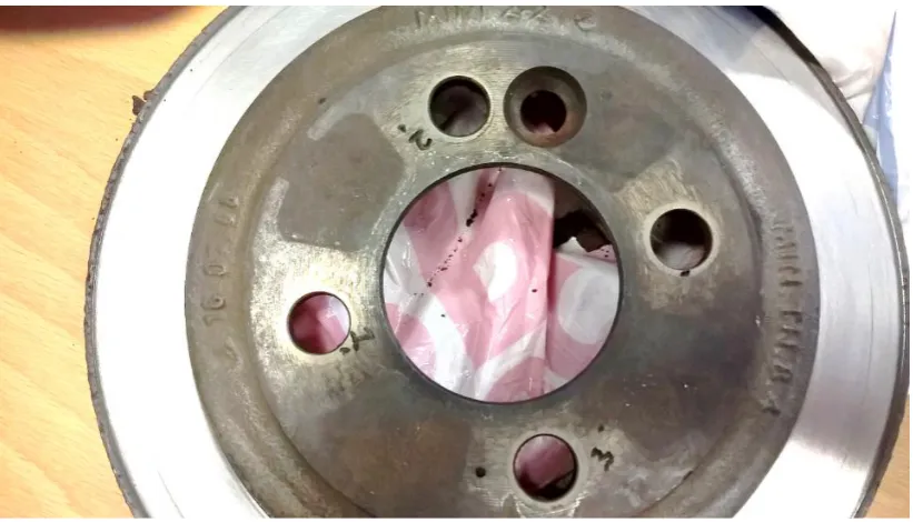
A car brake disc was obtained that had different thicknesses of surface rust on its different surfaces. Three areas of interest were chosen and the corners of the sensor were marked as areas 1, 2 and 3. The top left spots showing the sensor placement areas can be seen in Figure 9. The sensor’s ground clip was attached to the conductive outer rim of the disc and the sensor was placed on each of the three areas as seen in Figure 10. The output from pin 3 of the 555 timer was viewed on a Tektronix TDS2022C digital storage oscilloscope. As seen in Figure 11, the square wave frequency can be read from the oscilloscope screen. The results can be seen in the graph below and full results are available on request.
Figure 9: Car brake disc showing areas 1, 2 and 3
9
Figure 10: Brake disc showing sensor on area 1 and ground clip placement
10
Frequencies obtained from corrosion sensor on areas 1, 2 and 3
5.
Discussion of results
The frequencies obtained from all areas on each date was very different from that obtained by calculation. One reason for this could be that there is an air gap present between the layer of rust and the sensor. The rust is irregular, jagged and denticulate at microscopic level with some parts taller than others. The sensor is pushed up from the surface in places, allowing air to intrude and meaning that the capacitance of an irregular layer of air is being measured as well as the rust. It was found that the frequency seen on the oscilloscope reduced greatly when pressure was applied to the sensor. This effect could be seen as pushing the air out of the way and reducing the capacitance of the air gap.
Looking at the difference between the theoretical capacitance of the area of rust covered by the sensor obtained by calculation in this report, and the mean capacitance for area 1 obtained on day 1 from experiment,
𝐶𝑒𝑥𝑝𝑒𝑟𝑖𝑚𝑒𝑛𝑡𝑎𝑙 = 1.29956 × 10⁻¹⁰𝐹 = 1.30 × 10⁻¹⁰𝐹
𝐶𝑟𝑢𝑠𝑡 = 5.4679 × 10⁻¹⁰𝐹 = 5.47 × 10⁻¹⁰𝐹
Cexperimental is the total capacitance measured, including the capacitance of the rust and the
capacitance of the air gap. These two capacitances can be thought of as being in series in an electronic circuit, so
𝐶𝑒𝑥𝑝𝑒𝑟𝑖𝑚𝑒𝑛𝑡𝑎𝑙 = 𝐶𝑟𝑢𝑠𝑡× 𝐶𝑎𝑖𝑟 𝐶𝑟𝑢𝑠𝑡+ 𝐶𝑎𝑖𝑟
4 4.5 5 5.5 6 6.5 7 7.5 8 8.5 9
0 1 2 3 4 5 6 7 8 9
11 Solving for air gap capacitance Cair gives,
𝐶𝑎𝑖𝑟 =
𝐶𝑒𝑥𝑝𝑒𝑟𝑖𝑚𝑒𝑛𝑡𝑎𝑙 × 𝐶𝑟𝑢𝑠𝑡 𝐶𝑟𝑢𝑠𝑡− 𝐶𝑒𝑥𝑝𝑒𝑟𝑖𝑚𝑒𝑛𝑡𝑎𝑙
Inserting the above values for Cexperimental and Crust,
𝐶𝑎𝑖𝑟 =
1.30 × 10−10× 5.47 × 10−10 5.47 × 10⁻¹⁰− 1.30 × 10−10
= 1.71 × 10⁻¹⁰𝐹
In order to calculate what depth of air gap d this capacitance is produced by, the formula for capacitance is used with an εr of 1 and the area of the sensor A = 45mm x 22mm
= 0.00099m2:
𝐶𝑎𝑖𝑟 = 𝜀0𝜀𝑟𝐴
𝑑
𝑑 = 𝜀0𝐴 𝐶𝑎𝑖𝑟
=8.854 × 10−12× 0.00099
1.71 × 10−10
= 5.13 × 10⁻⁵𝑚 or 51.3𝜇𝑚
5.1Limitations of technique
This technique is currently not waterproof, as the presence of water would act as a conductor and negate the dielectric effect of any rust present. It cannot in its present form be used to detect rust on underwater structures.
It has been found that shallow rust, and patchy rust, do not give a signal. This is because the sensor covers an area that includes a part where bare metal shows through, touching the sensor, thus meaning that no capacitance effect is present.
This technique could be refined with further work to be used to sense the thickness of a layer of rust. At present, however, the readings obtained merely give an indication as to the presence or absence of a rust layer.
6.
Conclusions and Further Work
A system has been implemented that uses the dielectric properties of rust deposits to measure the presence and qualitative thickness of a corrosion layer on a steel brake disc. Further investigation is needed to quantify the depth of rust that can be detected using this method, and how it relates to the structural integrity of the remaining structure.
12 long time period. This may pave the way for the sensor, in miniature form, to become waterproofed and therefore be capable of being used in the splash or intertidal zones. Other corrosion manifestations could be detected using the capacitance method, for example, crevice and intergranular corrosion. In these cases, corrosion forms along discontinuities in the metal, forming a capacitive structure within the metal rather than on the surface. The sensing points either side of the dielectric would have to be redesigned, but the same method could be utilised.
This technique could also be used to detect other inclusions on the metal, for example corrosion under a paint layer, which would otherwise be missed. Further work is necessary into the capacitance of the paint layer and how the reading changes when corrosion is present.
Acknowledgements
The authors would like to acknowledge Mr F Noakes, without whose superior technician skill this project would not have succeeded.
References
1. G Koch et. al., 'International Measures of Prevention, Application, and Economics of Corrosion Technologies Study', NACE International, 2016.
2. K R Larsen, 'Evaluating sensors to monitor steel corrosion in concrete structures', NACE International, October 2015, Vol. 54, pp. 17 - 19.
3. D Chen et al., 'A Corrosion Sensor for Monitoring the Early-Stage Environmental Corrosion of A36 Carbon Steel', Materials, Vol. 7, pp. 5746 - 5760, August 2014. 4. G Rinaldi et al.,'Corrosion Sensor Development for Condition-Based Maintenance of Aircraft', International Journal of Aerospace Engineering, Article ID 684024, Vol. 2012, 2012.
5. A V Bray et al., 'Coating Effects in Microwave NDE in the Detection of Corrosion for Aircraft', NACE International, 2000.
6. X Qi and V J Gelling, 'A Review of Different Sensors Applied to Corrosion Detection and Monitoring', Recent Patents in Corrosion Science, Vol. 1, No. 1, pp. 1-7(7), June 2011.
7. N Yonemoto and K Shida, 'A Touch-Type Corrosion Sensor Including a Coil for High-Sensitive Detection of Initial Rust State', Japanese Journal of Applied Physics, Vol. 39, Part 1 no. 6A, 2000.
8. N Yonemoto and K Shida, 'Advanced Detection of Initial State of Iron Rust Based on Dual-Mode Sensing of a Touch-Type Corrosion Sensor with Magneto Supply', Japanese Journal of Applied Physics, Vol. 38, Part 1 no. 11, 1999