An Improved Speed Sensorless Control of Self
Excited Induction Generators Considering
Magnetic Nonlinearity
K. Roy and A. Chatterjee, D. Chatterjee and A. K. Ganguli
Department of Electrical Engineering, Jadavpur University, Kolkata, IndiaE-mail: [email protected], [email protected],{debashisju, ashoke_ganguli}@yahoo.com
Abstract—Self excited induction generators (SEIG) are widely used for wind power generation in remote areas. The challenge is to maintain constant voltage and frequency under variable load and variable wind speeds. In this paper a reactive power control technique of the generator partially through fixed capacitor bank connected at the stator terminals and switched dc power source is proposed for constant voltage operation. The dc power source can be a battery charged from a solar module and from the generator during light loaded condition. The capacitor provides the bulk excitation current for the induction generator (IG) while the inverter adds the reactive current needed to regulate the IG output voltage under variable wind speeds and loads. The method is simple and can also be applicable for a wider speed range of operation. Different simulations and experiments are performed on a real machine to validate the proposed concept.
Index Terms—self excited induction generators, speed-sensorless control, reactive power management, magnetization curve
I. INTRODUCTION
Three phase self excited induction machines with a squirrel-cage rotor are widely used for small scale power generation. The excitation capacitor bank is connected to the stator terminals for such schemes [1]-[6]. The main disadvantage of using capacitor for the supply of reactive power for self-excitation of an induction generator is poor voltage regulation. So it is not suitable for wider range of operating speed and load. To overcome this problem of voltage regulation some schemes proposed switched capacitor bank. But this type of discrete switching introduces sudden voltage fluctuations. As an alternate scheme, thyristorised control of the capacitors can be employed but it introduces voltage harmonics in the generated voltage. Various control strategies have been proposed to overcome these limitations. Some of these proposals use sensor less field-orientation algorithms to excite and control the induction generator [2]-[9] which introduce serious voltage harmonics problem. Of which there are some schemes which proposed shunt–connected PWM voltage source inverter supplying constant frequency voltage [5] and some schemes exist on
Manuscript received November 6, 2013; revised February 26, 2014.
supplying reactive current to the SEIG by using a static reactive power compensator [9]. Another strategy is also developed based on the instantaneous reactive power theory [10]. All these proposed algorithms assume a constant magnetizing inductance of the machine during its operation. Due to this insensitivity of the controller towards the variation of the mutual inductance at different operating points, the system becomes unstable or uncontrollable at some conditions.
In the proposed work, a strategy of a combination of inverter fed from a battery and fixed capacitances are considered for voltage stabilization of the system over a wide speed range. However, all the existing control schemes do not consider the variations in magnetizing inductances during the generator operation. Although this assumption simplifies the control schemes, this can introduce errors in various estimated quantities during the control of the generator or can add some unstable operating points or zones. The proposed technique assumes the nonlinear magnetization curve within its operating zone in order to improve the accuracy of inverter switching for voltage stabilization. The method is useful to widen the speed range of the generator without much variation of the generated voltage. The magnetization curve of the machine can be plotted during commissioning of the system. The inverter acts as a source of reactive power during the change in load or operating speed. The battery can be charged during light loaded conditions, which helps to stabilize the system voltage during such condition. A PWM strategy of switching for the inverter has been used to reduce the harmonics in the generated voltage. Various simulations and experiments are performed to justify proposed control strategy.
II. PROPOSED INDUCTION GENERATOR MODEL
The induction generator is modelled in synchronously rotating frame. The stator and rotor voltage equations in d-q synchronous reference frame can be written as
ds
ds s ds s qs
d
V
r i
dt
qs
qs s qs s ds
d
V
r i
dt
(2)0
dr(
)
r dr s r qr
d
R i
dt
(3)0
R i
r qrd
qr(
s r)
drdt
(4)The flux linkage equations are,
ds
L i
s dsL i
m dr
(5)qs
L i
s qsL i
m qr
(6)dr
L i
r drL i
m ds
(7)qr
L i
r qrL i
m qs
(8)III. PROPOSED TECHNIQUE FOR CAPACITOR
CALCULATION
The steady state model of the machine is considered for capacitor calculation where the derivative terms of (1)-(4) are zero. If leakage inductances are neglected for simplicity in equations (5)-(8),
qs,
qr qm and,
ds dr dm
.where,
dm and
qm are d-q axes air gap flux linkages.Therefore, from equations (1)-(4),
ds s ds s qm
V
r i
(9)qs s qs s dm
V
r i
(10)0
R i
r dr
(
s r)
qm (11)0
R i
r qr
(
s r)
dm (12)Also,
dm
L i
m dm
(13)qm
L i
m qm
(14)where,
i
dm
i
dr
i
ds and,i
qm
i
qr
i
qsNeglecting stator resistance in equation (9) and (10),
ds s qm
V
(15)qs s dm
V
(16)Assuming air-gap flux orientation of d-axis,
dm m
and
qm0
. The latter givesi
qm
0
from equation (14).Also substitution of the same condition in equation (11) yields,
0
r drR i
(17)As the rotor resistance is a non-zero quantity,
i
dr
0
from equation (17).Therefore,
i
ds
i
dm.Thus the air-gap flux can be expressed as,
m
L i
m ds
(18)where,
i
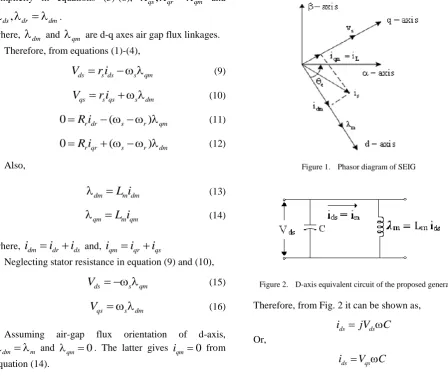
ds is the stator magnetizing current of the machine.The corresponding phasor diagram for the machine is shown in Fig. 1. The capacitor bank is used as a bulk uncontrolled source of reactive current, whereas the inverter provides the controlled source of reactive power to regulate the stator voltage current. The design criterion for the capacitor is considered is such that it has to supply the whole reactive-current needed to generate the nominal voltage under nominal speed and no load conditions. Thus the current
i
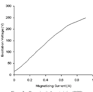
ds will be supplied by the capacitor only. Based on equations (15)-(18), the d-axis equivalent circuit for the generator can be developed, which is shown in Fig. 2.Figure 1. Phasor diagram of SEIG
Figure 2. D-axis equivalent circuit of the proposed generator
Therefore, from Fig. 2 it can be shown as,
ds ds
i
jV
C
Or,
ds qs
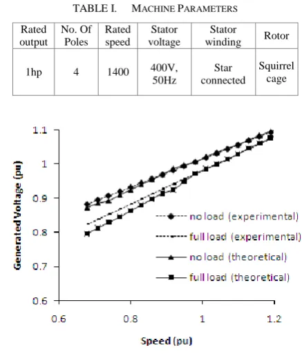
Figure 3. Open circuit characteristics (OCC)
To calculate the capacitance for the purpose to provide total reactive power at no load condition under nominal speed generating nominal voltage, the open circuit characteristics (OCC) of the machine can be considered. The magnetization curve obtained from the experiments for the given machine at nominal speed is shown in Fig. 3. The excitation voltage and magnetizing current of Fig. 3 are the q-axis stator voltage
V
qs and d-axis stator currentds
i
respectively. Fig. 3 shows high degree of nonlinearitybetween
V
qs andi
ds. Therefore assumption of a linearmagnetizing curve will provide a calculated value of capacitor that can result in wider variation of generated voltage with rotor speed. This can result in increased amount of reactive power to be supplied by the compensating inverter resulting in its higher size design. In the suggested method this nonlinearity has been taken into account for calculation of the required excitation capacitance. The q-axis stator voltage
V
qs is a linearfunction of
m as observed from (16). Thus
m can beobtained as a non-linear function of
i
ds similar to OCC.The mixed model equations [11] for
m takes the form of,2
1 2
m
k
k i
dsk i
ds
(20)where
k
,k
1 andk
2 are constants which can be obtained from the magnetization curve for the machine. Thus solving equations (16), (19) and (20),2
1 1 2
2
4 (
)
2
qs r
r
r qs
v
k
k
k
k
C
k
v
Farads (21)Equation (21) can be used to calculate the initial capacitance for the generator at no load rated voltage.
IV. PROPOSED CONTROL TECHNIQUE
A scheme of the proposed system is shown in Fig. 4. The self excited induction generator system consists of a conventional three phase squirrel cage IM, driven by a prime mover (a DC motor is used as the prime mover for experimental purpose). The system does not require any position or speed sensor. The IM stator is connected to an ac load, a fixed capacitor bank and a current controlled inverter. The capacitor bank and the inverter supplied from a battery provide the reactive current needed to excite the IM. The battery is charged from a solar module to keep its voltage constant. This scheme can operate at a remote place where no utility supply is available. The capacitor bank will act as an uncontrolled frequency-dependent reactive current source that provides the bulk excitation and the inverter will act as a controlled reactive current source that is used to regulate the stator voltage and frequency. Here the stator reactive current will be the sum of the uncontrolled capacitor-bank reactive current and the inverter reactive current. The inverter reactive q-axis current reference is kept at a minimum value near zero and the d-axis current reference is generated from the voltage loop as shown in Fig. 4.
The generation of unit vectors for air gap flux orientation can be achieved through stationary reference frame stator voltage equations as,
s s s s
d
V
r i
dt
(22)s s s s
d
V
r i
dt
(23)Neglecting the stator resistance drops and stator leakage inductances in equations (22) and (23),
m
v dt
s
(24)m
v dt
s
(25)Therefore the unit vectors are,
2 2
cos
(
)
(
)
m em m
(26)2 2
sin
(
)
(
)
m em m
(27)V. SIMULATION AND EXPERIMENTAL RESULTS
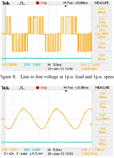
The proposed algorithm was tested experimentally with the scheme shown in Fig. 4. The inverter q-axis reference current was kept at a minimum value so that no active power is drawn from it. The machine specification is given in Table I. The calculated capacitor considering magnetic nonlinearity to generate nominal voltage at nominal speed is 13uF was initially connected with the stator. The speed was varied by varying the DC motor speed and corresponding generated voltage both at no load and full load was recorded. The theoretical and experimental variation of the generated voltage is shown in Fig. 5 which shows a good conformity between the two. Then the same experiment was repeated with a capacitance of 10uF, which is the value considering a linear magnetic circuit of the machine. The comparative experimental voltage variation against the speed of the generator for both the capacitances is shown in Fig. 6 which shows a clear advantage of the proposed method. Then the proposed control loop was initiated and the same speed variation at full load and no load was tried. The generated voltage was recorded against the rotor speed. The comparative voltage variation with and without control at full load with 13uF capacitor is shown in Fig. 7. It is evident that the proposed technique maintains a good voltage regulation over a speed range of 0.65p.u. to 1.2p.u., which can be of good practical value. The corresponding line voltage and line current at 1.0p.u speed and 1.0p.u. load is shown in Fig. 8 and Fig. 9 respectively.
TABLE I. MACHINE PARAMETERS
Rated output
No. Of Poles
Rated speed
Stator voltage
Stator
winding Rotor
1hp 4 1400 400V, 50Hz
Star connected
Squirrel cage
Figure 5. Theoretical and experimental variation of the generated voltage (at no-load and full-load)
Figure 6. Comparative experimental voltage variation against the speed of the generator for both the capacitances
Figure 8. Line to line voltage at 1p.u. load and 1p.u. speed
Figure 9. Line to line current at 1p.u. load and 1p.u. speed
VI. CONCLUSION
A technique for calculation of capacitance considering magnetic nonlinearity for three phase SEIG is shown. The proposed method widens the operating speed range of the generator with stabilized terminal voltage. The method requires an additional inverter for supplying the reactive power only during the speed or load variation. The required inverter power can be shown to be much less than the capacity of the SEIG and for the proposed scheme a solar panel is used to supply inverter dc power. The proposed method is simple to implement and will require no high-end hardware. Various experimental results are shown to validate the proposed concept.
ACKNOWLEDGMENT
K. Roy thanks UGC, India for supporting this work. A.Chatterjee thanks CSIR, India for providing financial support.
REFERENCES
[1] T. Ahmed, O. Noro, E. Hirak, and M. Nakaoka, “Terminal voltage regulation characteristics by static var compensator for a three-phase self-excited induction generator functions,” IEEE
Trans on Indus. Appl., vol. 40, no. 4, pp. 978-988, Jul./Aug. 2004.
[2] T. Ahmed, K. Nishida, and M. Nakaoka, “A novel induction generator system for small-scale AC and DC power applications,”
in Proc. IEEE PESC, Recife, June 2005, pp. 250-256.
[3] N. H. Malik and A. H. Al-Bahrani, “Influence of the terminal capacitor on the performance characteristics of a self excited induction generator,” IEE Proc. C., vol. 137, no. 2, pp. 168-173, Mar. 1990.
[4] N. H. Malik and A. H. Al-Bahrani, “Steady state analysis and performance characteristics of a three phase induction generator self excited with a single capacitor,” IEEE Trans. on Energy
Conv., vol. 5, no. 4, pp. 725-732, Dec. 1990.
[5] G. Marra and J. A. Pomilio, “Self-excited induction generator controlled by a VS-PWM bidirectional converter for rural
applications,” IEEE Trans. Ind. Appl., vol. 35, no. 4, pp. 877-883, July/Aug. 1999.
[6] O. Ojo and I. Davidson, “PWM-VSI inverter assisted stand-alone dual stator winding induction generator,” in Proc. Conf. Rec.
IEEE-IAS Annu. Meeting, Oct. 1999, pp. 1573-1580.
[7] M. S. Miranda, R. O. C. Lyra, and S. R. Silva, “An alternative isolated wind electric pumping system using induction machines,” IEEE Trans. on Energy Conv., vol. 14, pp. 1611-1616, Dec. 1999.
[8] M. Naidu and J. Walters, “A 4-kW 42-V induction-machine-based automotive power generation system with a diode bridge rectifier and a PWM inverter,” IEEE Trans. Ind. Appl., vol. 39, no. 5, pp. 1287-1293, Sep./Oct. 2003.
[9] E. Suarez and G. Bortolotto, “Voltage frequency control of self-excited induction generator functions,” IEEE Trans on Energy
Conv., vol. 14, no. 3, pp. 394-401, Sep. 1999.
[10] R. Leidhold, M. I. Valla, and G. Garcia, “Induction generator controller based on the instantaneous reactive power theory,”
IEEE Trans. on Energy Conv., vol. 17, pp. 368-373, Sep. 2002.
[11] D. Chatterjee, “A novel magnetizing-curve identification and computer storage technique for induction machines suitable for online application,” IEEE Trans. Ind. Electron., vol. 58, no. 12, pp. 5336-5343, Dec. 2011.
K. Roy was born in Thakurnagar, India in
1982. He received the B.E., and MEE degree in Electrical Engg from Jadavpur University, Kolkata, India, in 2005 and 2007 respectively. Currently, he is a Research Scholar in Electrical Engg. Department at Jadavpur University, Kolkata.
A.Chatterjee was born in Burnpur, India in
1986. He received the B.Tech. and MEE degree in Electrical Engg from West Bengal University of Technology and Jadavpur University, Kolkata, India, in 2008 and 2011 respectively. Currently, he is a Research Scholar in Electrical Engg. Department at Jadavpur University, Kolkata.
D. Chatterjee was born in Kolkata, India in
1969. He received the B.E.degree in Electrical Engg. from Jadavpur University, Kolkata, India, in 1990 and M. Tech. Degree from IIT Kharagpur and Ph.D. degree in Electrical Engg. from Jadavpur University, Kolkata, in 1992 and 2005 respectively. From 1992 to 2002, he worked as a Sr. Executive Engineer in National Radio Electronics Co. Ltd. in Drives and Automation System, Development Executive in Crompton Greaves Limited-Industrial Electronics group and Asst. manager R&D in Philips India Ltd. in Lighting Electronics Division. Currently, he is Associate Professor in Electrical Engg. Department at Jadavpur University, Kolkata. His main research interest includes Control of Electric Drives & Power Electronics, Renewable Energy Generation & Control.
A. K. Ganguli was born in Kolkata, India in