Vol.9 (2019) No. 6
ISSN: 2088-5334
A Gesture-based Recognition System for Augmented Reality
Vinothini Kasinathan
#, Aida Mustapha
*,
Asti Amalia Nur Fajrillah
+#
Faculty of Computing, Engineering and Technology, Asia Pacific University of Technology and Innovation, Technology Park Malaysia, 57000 Kuala Lumpur, Malaysia.
E-mail: [email protected]
*
Faculty of Computer Science and Information Technology, Universiti Tun Hussein Onn Malaysia, 86400 Parit Raja, Johor, Malaysia.
+
School of Industrial Engineering, Telkom University, 40257 Bandung, West Java, Indonesia
Abstract— With the geometrical improvement in Information Technology, current conventional input devices are becoming
increasingly obsolete and lacking. Experts in Human Computer Interaction (HCI) are convinced that input devices remain the bottleneck of information acquisition specifically in when using Augmented Reality (AR) technology. Current input mechanisms are unable to compete with this trend towards naturalness and expressivity which allows users to perform natural gestures or operations and convert them as input. Hence, a more natural and intuitive input device is imperative, specifically gestural inputs that have been widely perceived by HCI experts as the next big input device. To address this gap, this project is set to develop a prototype of hand gesture recognition system based on computer vision in modeling basic human-computer interactions. The main motivation in this work is a technology that requires no outfitting of additional equipment whatsoever by the users. The gesture-based had recognition system was implemented using the Rapid Application Development (RAD) methodology and was evaluated in terms of its usability and performance through five levels of testing, which are unit testing, integration testing, system testing, recognition accuracy testing, and user acceptance testing. The test results of unit, integration, system testing as well as user acceptance testing produced favorable results. In conclusion, current conventional input devices will continue to bottleneck this advancement in technology; therefore, a better alternative input technique should be looked into, in particularly, gesture-based input technique which offers user a more natural and intuitive control.
Keywords— hand gesture; e-learning; human-computer interaction.
I. INTRODUCTION
In recent years, people have grown far more interested with augmented reality systems. These are systems which overlays graphics onto real-time display. In fact, according to the ABI Research Study in 2009, augmented reality technology is thought to grow from producing USD 6 million in profit in 2008 to approximately USD 350 million in 2014. With the advent of augmented reality systems, many experts in Human-Computer Interaction (HCI) found that there is a need to improve the many aspects of interaction between humans and computers. The unnaturalness of some conventional input devices such as mouse, keyboard and joystick causes these respective devices to be incapable of completely bridging the gap found between human and computer interaction. [1] believed that Human Computer Intelligent Interaction (HCII) can only be achieved when a user is able to interact naturally with a computer, just as how human-human interaction takes place every day.
The presence of these technologies have made computer input and output a lot more sophisticated now than a decade ago. However, current conventional input devices are a huge bottleneck in the bandwidth of information transition between man and machine as the unnaturalness of these devices inadvertently cause the ‘gulf of execution’ [2]. Gulf of execution is a term used to describe the gap between the user’s intentions and actions to be done in order to execute them. [3] believed that one fundamental way of reducing the gulf of execution is to make the input actions of user as similar to the thoughts that motivated the actions. This is however, not possiblewith the current array of conventional input devices as these devices promote trained behaviors, rather than exploiting analogies to existing human skills such as pointing, and dragging [4].
precise input devices are highly demanded. A simple example of such a system would be the Catheter Robotics Manipulation System by CRI [5]. This pioneering medical system allows surgeons to remotely manipulate EP catheters. The remote control replicates the functions of the catheters, effectively eliminating the gulf of execution in terms of similarity to the real scenario and precision of the input device. Current input mechanisms are unable to compete with this trend towards naturalness and expressivity which allows users to perform natural gestures or operations and convert them as input.
It is said that fluidity and expressiveness of human gesture is a fundamentally important component of interpersonal communication [6]. At present, conventional HCI devices are also rigid in their controls as well as ergonomics and to some degree, their designs, requiring users to be in constant physical contact with them in order to utilize these devices. Some users are unable to operate a system via mouse and keyboard, which is inarguably the most popular input devices for conventional computer systems as of today, because of multiple reasons [7]. [8] considered conventional input devices to be more oriented towards the input requirements of the computer, rather than that of the user, and suggested that gesture input may be suitable for people who are unable to use a keyboard or are unwilling to do so, preferring a system which responds to manual gestures.
Because of the rigidity of these devices, most of the time, one type of conventional device is best suited for only a set of tasks. In the case of mouse and keyboard, for example, mouse is better in pointing and navigation tasks but is terrible in word processing while the keyboard is the exact opposite. In their Eyeflyer research, [9] showed that the movement efficiency, in words per minute on a QWERTY virtual keyboard via a mouse is 15 words per minute (wpm), a lot slower than the average rate of 33 wpm on a standard QWERTY keyboard [10]. Another example would be the tablet and mice. The tablet is considered to be one of the best pointing input devices, however, it is inferior to the mice in terms of dragging tasks [11]. Based on the famous Fitt’s law, the efficiency of input devices in relation to the different tasks to be executed and is considered to be a key foundation in input designs.
This project focuses on allowing users to remotely interact with their system via hand gestures in the field of computer vision, giving way to a more flexible and natural approach to HCI; an alternative computer input technique. This project is not intended to revolutionize the HCI field, but rather a proof of concept work of incorporating computer vision into HCI for a more natural and intuitive means of computer interaction.
Most common Graphical User Interfaces (GUIs) in many systems are still limited to the popular keyboard and mouse input devices for efficient interaction. However, gesture recognition is a technique which allows computers to understand bodily language, much like humans do, thus creating a richer interaction bridge between machine and man. This allows human to interface with machine, and interact naturally without the aid of any mechanical devices. Input devices based on gesture recognition takes human gestures as an input signal, and interprets it vi a mathematical algorithms. Gestures can be of any shape or
form, even bodily motion. The most popular form of input is usually taken from the face or the hand. One of the more important reasons as to why experts in Human-Computer Interaction (HCI) are so eager to incorporate gestures as a form of input, is because of the naturalness of gestures. According to [8], conventional input devices are more oriented towards the input requirements of the computer than the user, in that they are precise and unambiguous, pointing out that the only way to produce a more natural style of interaction with the computer is to build an interaction technique with human-human communication as the foundation. A study conducted by [12] on the effects of gestures and speech for graphic image manipulation yielded surprising results. The method of his experiment was simple; participants were to sit in front of a fast, high resolution bitmapped monochrome graphics terminal. They were to perform image manipulating tasks via three different communication modes: gestures only, speech only and the last which combines both gestural and verbal communication. The research found that 58.3% of subjects preferred to use both verbal and gestural input with 22.2% preferring speech only and 19.2% preferring gestures only. [12] found out that for the task of graphic manipulation, gesture communication is intuitive, requiring no previous experience and is therefore equally accessible to all computer users, not just expert users. This view that gesture communication is intuitive is also sided by [13] in his work with two-dimensional mouse gestures.
Another advantage of hand-gesture input is that it has the potential to cause a wide spread recognition of sign language. [8] pointed out the benefits that a person, who communicates exclusively through sign language, can gain from a sign language-to-synthetic speech system. [14] also noted the liberating effects when such a system is applied to problems where people who exclusively use sign language as a communication mode interact with hearing people. A gesture recognition system can convert finger-spelling to speech for communication with hearing people, and a speech to text system for the device’s user to read replies as a solution. Other works that developed gestural recognition inputs based on sign language include [15-17].
The data glove has the capability to perform the same measurements in a fraction of the time, using a less skilled operator and with more repeatable results. Two decades later, the Catheter Robotics Manipulation System was officially released.
In summary, gesture-based interactions in a computer system is imperative due to its naturalness and intuitiveness. Gestures are also the basis of sign language recognition system and can be used in a cumbersome environment or where gesture input is more appropriate for tasks such as graphic object manipulation. Gesture-based inputs also promotes intentional user imprecision and are able to be utilized by people who are unwilling or unable to use a keyboard. An example of an input device which utilizes computer vision is the Flow Mouse. However, this is only possible due to the advances in imaging technologies. Back then, exoskeleton or gloves were used to measure the position of fingers and thumb, affixed to the exoskeleton is a 3-space receiver which would allow the transmitter to relatively locate the hand in space. An example of an input device which uses such a technique is the Power Glove. Flow Mouse and Power Glove will be discussed next.
A. Flow Mouse
Flow Mouse is a pointing device and a gesture input system based on computer vision developed by [21]. In order to capture the motion of the hand, Flow Mouse utilizes optical flow techniques, instead of the more common absolute position-based tracking methods. Instead of forcing the users to continuously use it, FlowMouse has a natural mode switch which would enable and disable the feature, so as to not only prevent accidental capturing of unintended gesturing, but to also allow for a “clutching” action that a pointing scheme needs. In general, FlowMouse is described as an input technique that works similarly to an optical mouse sensor in the sense that the mouse velocity is determined by the relative motion of the hand under the camera. Grayscale images extracted from the camera will be processed and used to determine the vector of a particular moving object, specifically, the hand in this case. This approach allows the developers to avoid the vulnerability of absolute tracking techniques.
In [21], Flow Mouse was evaluated by six participants of the age range between 30 and 55, based on the Fitt’s Law to measure the performance of the Flow Mouse in comparison with a trackpad. The experiment revealed that the trackpad fared better than the Flow Mouse but participants concluded that Flow Mouse was rather intuitive and felt natural to work with. The main functionality of the Flow Mouse is to allow users to control the mouse pointer with the motion of their hand, instead of the positioning of their hand, emphasizing heavily on optical flow technique to achieve this. It also supports two-dimensional pointing while still providing users with intuitive way of interaction. The key features include (1) a gesture recognition based on computer vision, (2) an optical flow technique, (3) a natural mode switch, and (4) a two-dimensional pointing compatibility. Nevertheless, Flow Mouse has few shortcomings that include inability to recognize gestures that rely on shape or contour of hands, poor implementation of natural mode switch, simulation only based on mouse movement, resulted in relatively weak
Fitt’s performance index in comparison with trackpad, and inability to differentiate object in motion.
B. Mattel Power Glove
The Mattel Power Glove was a glove-type gesture input device built based on data gloves [22]. It was designed for use in virtual reality systems, specifically the Nintendo Entertainment System (NES) even though it only has a 2-bit finger bend resolution. The Power Glove operates in one of two modes, either low resolution or high resolution. When the Power Glove is in low resolution mode, it emulates a joystick. If the glove is pointed upwards, then the only information that the host computer receives from the glove is the code for ‘up’. In short, it reports the position of the hand on the x and y axis. All information about the position of the hand in space and the amount of finger bend is lost when in this low resolution mode, rendering gesture recognition completely irrelevant in this mode. Conversely, when in high resolution mode, the glove sends all information about hand position and finger bend to the host computer for gesture recognition [23].
The Power Glove uses material that covers the thumb and fingers with different electrical resistance depending on how much it is flexed. The degree of bentness is expressed in terms of integers as follows. 0 means fully extended, 1 means a little bent, 2 means more bent than straight, and 3 means fully bent. The Power Glove was designed solely for the NES, and it clearly shows in its functionalities. The x and y axis position report was implemented to emulate the controls of a joystick, while the tracking of the “roll” hand orientation is designed specifically for flight games, in which it simulates the raising of one wing and the lowering of the other in most flight technologies. Power Glove automatically detects flexing of fingers and perform tracking motion in three-space. Nonetheless, flexing of fingers is only represented by four states and is completely dependent on how the material surrounding the fingers is bent. This results in inaccurate flexing representation. In addition, there is the Gorilla Arm effect when users are exposed to prolong use of the Power Glove because they have to point knuckles to the receiver array constantly.
As conclusion, after examining both Flow Mouse and Power Glove, the main requirements of a gesture-based input device can be derived clearly. Among the narrowed functionalities that will be the bases of the proposed hand gesture system are as follows (1) imaging processing technique to detect and track hand, (2) acquisition and recognition of hand gestures after processing, (3) two-dimensional pointing compatibility, (4) implementation of other mouse basic operations, (5) ability to filter objects that are not of interests, and finally (6) feature extraction to complement mouse operations.
The remaining of this paper is structured as follows. Section 2 presents the proposed Hand Gesture Recognition System, Section 3 presents the prototype development, Section 4presents evaluation and discussions, and finally Section 5 concludes with indication for future research.
II. MATERIALS AND METHODS
gestures performed by the users. These hand gestures will then be interpreted by the system into input commands. The core functionalities of the system are two-fold; (1) to display of video feedback on computer via webcam and (2) to detect and track the user's hand. In addition, the system should be able to perform feature extraction on detected hand as well as mouse control simulation. System development adopted the hand detection framework by [24]. Fig. 1 shows the steps involved in detection, tracking and classification of hand gestures.
A. Video Acquisition
The first and foremost module of the framework is to take raw video feed from the camera and feed it into the system. Videos are made of multiple frames, and each of these frames are segmented individually to be processed by the next module.
Fig. 1 Hand detection framework [24].
B. Preprocessing
Preprocessing consists of two tasks: background segmentation and skin segmentation. Fig. 2 shows the breakdown of the segmentation process.
Fig. 2 Segmentation process breakdown.
• Background Segmentation
In this research, the background segmentation model was adopted from the Background Subtraction Model by [25] as shown in Fig. 3.
Fig. 3 Illustration of background subtraction model.
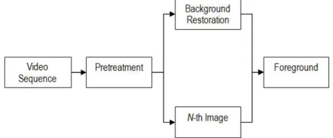
The background of a video can be learned by constantly storing and updating the average gray level of each pixel as the video runs [26]. By differentiating the current frame, the N-th frame, with the averaging background model, the image obtained would represent the potential region of foreground objects, as these pixels differ from the average gray level stored in the background model.
The next step is thresholding, a technique used to extract the shape of moving objects based on a defined threshold level [27]. However, because the output foreground will be in binary form, skin segmentation cannot be applied to it, resulting in every object in foreground to be detected as region of interest by the system. In order to overcome this problem, this project used a method in which skin segmentation can be done on the foreground objects. The output of the thresholding, the binary image, will now be used as a mask to be superimposed unto the N-th image currently under process. The result of the implemented method is shown in Fig. 4, allowing skin segmentation to be done next.
Fig. 4 Example of implemented background subtraction.
• Skin Segmentation
Skin segmentation algorithm is used to detect which region of the input image has skin color and then marked. There are several skin detection methods, all of which utilizes different space color, two of which are the normalized RGB space color and the YCbCr space color. The criteria to look out for filtering are computational complexity and the accuracy of likelihood.
Normalised RGB Colour Space. The RGB colour model is one of the most recognized color spaces in which the three main primary colors are represented in their respective axis. Their combination would bring about a multitude of other colors. This color space is used for the input and output of many electronic systems, particularly in displaying images. In computer systems, these color components are stored as an integer value ranging from 0 to 255. However this space color is very luma-dependent and detection of a certain range of color may be unreliable under different lighting conditions [28]. Normalized RGB space color takes this into account and forms a chromatic color space, which removes luminance and can be defined by the formula in Equation 1 [29].
= /( + + ) = /( + + ) + + = 1
(1)
clustered and can be represented by a Gaussian model N(m, C) in Equation 2 adopted from [30] where:
= ( ) where = [( )] = ( − )[( − )]
(2)
From the model, the probability of a pixel representing skin color can be computed in Equation 3 as follows.
( , ) = exp [−0.5(− )] (−1)( − )" where = [( , )]
(3)
YCbCr Colour Space. YCbCr color space separates the RGB color channels into individual components, reducing redundancy data that is present in said channel. This color space stores luminance information in a single component, Y, while Cb and Cr are the blue and red chrominance components respectively. The formula for converting RGB into YCbCr is shown in Equation 4:
# = 0.299 + 0.587 + 0.114
= 128 − 0.168736 − 0.331264 + 0.5 = 128 + 0.5 − 0.418688 − 0.081312
(4)
where R, G, B, Y, Cb, Cr ϵ {0, 1, 2, 3, 4, ..., 255}.
YCbCR is luma-independent and the condition whereby a pixel is considered to be representing skin is when 85 ≤ Cb
≤ 135 and 135 ≤ C ≤ 180,Y ≥ 80. In comparing between
the two skin segmentation algorithms; the Normalised RGB Color Space and YCbCr Color Space, [31] found that in terms of computational complexity, the YCbCr algorithm is faster than the RGB Color Space algorithm with 81.3% accuracy of likelihood as opposed to 69.1% by the RGB algorithm.
C. Feature Extraction
In gesture-based recognition system, features to be extracted are inherent characteristics of an object. From the binary mask obtained from the segmentation, the system will be able to extract the width, height, center position, contour and convex hull as shown in Table 1.
TABLEI
FEATURES EXTRACTED FROM OBJECTS.
Extracted Explanation
Width The width would be calculated based on the horizontal length of the Region of Interest (ROI)
Height The height would be calculated based on the vertical length of the ROI
Center Position The center position can be calculated based on the ROI
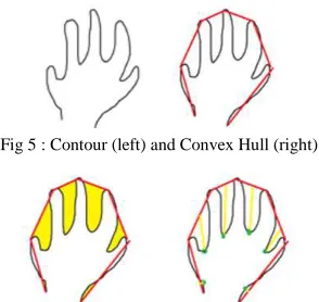
Contour The silhouette of the hand mask image (Fig. 5)
Convex Hull Derived from the contours previously found (Fig. 5)
Convexity Defects and Depth Points
Depth Points and Derived from defects found present in between a convex hull and a contour (see Fig. 6)
Wrist Detection Derived from the points of defects (Fig. 7)
Note that wrist detection feature can be extracted from the points of the defects because the depths differ from one another, with the ones between the fingers being the deepest. The location of the wrist is obtained by assuming that the defects found on the wrist are the shallowest.
Fig 5 : Contour (left) and Convex Hull (right)
Fig. 6 Convexity Defects (left) and Depth Points (right).
Fig 7 Wrist Detection.
D. Classification
The classification module in the gesture-based recognition system deals with the recognition of static hand gestures via pattern recognition. The classifier used in this project is the K-Nearest Neighbor (k-NN) classifier, which is a widely used pattern recognition and machine learning algorithm. Based on a majority vote from its neighbors, a test query can be classified, as the class most common amongst the neighbors. Much like any other machine learning algorithm, K-NN has two phases, the training phase and classifying phase.
• Training Phase. During this phase, the k-NN algorithm trained the features to recognize classes. This algorithm store the entire training pattern and their respective classification results. The time complexity for training is θ=(1).
• Classifying Phase. When a vector is fed into the algorithm, the algorithm performed a check on its surrounding neighbors up until a distance of $k$. The given vector is then classified as a class of which has the most votes. The time complexity of this phase is θ=(dn), where d is the length of the training document.
E. Gesture Recognition Algorithm
of generated output as outcome of the gesture-based recognition system.
In simple image manipulation, the input is the source image. For each image, the algorithm will can each pixel column by row and manipulate the pixel accordingly. The output will be the manipulated image. The nested loop would ensure that each pixel is scanned column by column on the first row and then continued on to the next row. Based on the conditions set in Algorithm 1, these pixels are manipulated accordingly, such as painting the pixels with different colors and such.
The objective of background subtraction is to separate the foreground from the background image. Based on Algorithm 2, an image matrix which would store the average background model of the frames is initialized during the first run of the system. After which, the foreground of the frame is defined by differentiating the current frame with the average background model. Morphology process is performed onto the result for a better image. Finally, the foreground mask is applied to the original source of the frame. This would result in the final product of the frame containing only the foreground in color, allowing skin filtering process to be performed next.
In finding the contour and filtering, all contours are traced from the binary image input and store them in an array. Every contour traced is scanned through, if the size of the contour is less than the minimum size defined, then the contour is deleted from the storage memory. After filtering contours which do not meet the minimum size, comparison between the size of the remaining contours is performed. The largest contour will then be selected as the object of interest. The process is shown in Algorithm 3.
Given the input of hand contour and the array of defects, next, in order to find the palm position, the defects found on the contour are filtered based on the minimum depth size set. After which a minimum enclosing circle is build based on
the defects left. The center and radius of the circle is stored into a buffer. The average positioning of the palm center and the palm radius is then derived from the buffer. The output from the process are the palm center and the palm radius is shown in Algorithm 5.
Finally, finger calculation is performed based on the defect list, palm center and palm radius as shown in Algorithm 5. The start points of the defects are stored as potential finger tips location. The length of the finger tips point to the center of the palm is calculated. If the potential point's $y$ position is higher than the center of the palm and its distance from the center of the palm is larger than the radius of the palm, then it is considered to be a fingertip.
F. Prototype Development
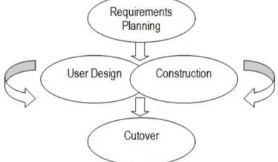
The gesture-based had recognition system was implemented using the Rapid Application Development (RAD) methodology [26] as shown in Fig. 8. RAD involves both structured techniques as well as iterative techniques such as prototyping. This methodology places emphasis on development speed through prototyping cycles in order to quickly produce a fully functional system in a short time period. There are 5 phases in this methodology; requirements planning, user design, construction, and cutover. Based on the RAD methodology, the output system will be presented in three prototypes.
Fig. 8 Rapid Application Development (RAD) methodology.
1) Prototype 1
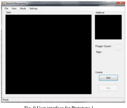
In the first prototype of the system, only the core functionalities of the system was implemented. The prototype will integrate the following core functionalities, (1) display of video feedback on computer via webcam, (2) HSV and YCbCr skin segmentation options, (3) background segmentation, and (4) detection and tracking of the user's hand. This first prototype will be able to capture video from the webcam connected to the computer.
enable or disable background segmentation and selection of color spaces used in skin segmentation will be provided in this first iteration of the system. Finally, the detection and tracking of the user's hand is another functionality that will be implemented into the first prototype. Fig. 9 shows the user interface for Prototype 1.
Fig. 9 User interface for Prototype 1.
At the initialization of the system, it first checks the availability of a web camera on the system. If a web camera is unavailable, the only input option that will be accepted is a valid AVI video file. However, if a web camera is available, the user is given the option of selecting the option of the input of the system, either via live feed from the web camera connected to the computer, or a valid AVI video file. In the case whereby the video file given is invalid, the system will prompt the user for another valid video file. After successfully creating a capture, the system will continuously retrieve frames from the feed. If background subtraction is enabled, the averaging background model is first updated, before the extraction of foreground is done. Pre-treatment of the foreground will then be done during the preprocessing of the frame. Next, depending on the user's selection of colour spaces to be used, either HSV or YCbCr will be used to segment skin pixels from the foreground that was extracted previously.
Identification of the contour of the hand is performed next, if a contour which fits the specification as stipulated by the developer is found, the contour is redrawn by the system and then the system forks into two paths. In the first path, a boundary rectangle will be drawn around the detected contour, effectively allowing the system to track the hand detected. In the other path, the contour of the hand is displayed unto the secondary picture box on the interface, allowing a clear view of what is currently `seen' by the system. Regardless of whether a hand contour is detected or not, the system will loop again, retrieving the next frame of the feed. The loop will only end if prompted by the user or if a video feed, the video ends.
2) Prototype 2
In the second prototype of the system, enhanced functionalities were integrated implemented. The enhanced functionalities focused on feature extraction on detected hand and the mouse control simulation in `Mouse' mode.
After the detection and tracking of the hand is completed, feature extraction was carried out for the following features; Convex Hull, Convexity Defects, Palm Center, Finger Tips, and Hand Segmentation. Next, these features were used to provide the user with a novel mouse control simulation when the system is operating under `Mouse' mode. Mouse features that was implemented include mouse movement, left click, right click, drag capability, and mouse wheel capability. Fig. 10 shows the interface for Prototype 2.
Fig. 10 User interface for Prototype 2.
As with the first prototype, the system would first check the available input mode and then preprocess the frames by performing background subtraction if necessary and then skin segmentation. The difference comes right after the identification and redrawing of hand contour is carried out. Instead of forking into two paths of simply drawing a boundary rectangle and displaying the contour frame, feature extraction is added into the activity. First, the convex hull would be derived from the newly drawn contour. With the convex hull of the contour of the hand obtained, the system will then derive the convexity defects of the contour. After deriving some of the more obvious features of the contour, the system will then fork into two paths for more advanced feature extractions.
The first path will identify the fingertips of the hand, determining the tip of their points. Next, the number of fingers currently extended is counted and two of the main fingers, determined by their lengths, are identified. The second path will identify the palm position of the hand using the previous features extracted before the forking. Next, the hand itself is segmented based on the detected wrist location. At the end of the fork, the system then makes the join transition to redraw the newly processed contour again; this newly drawn contour will then be displayed on the secondary picture box available on the main GUI. In the next activity, the system executes the mouse function, in which, all the previously derived features will be utilized and interpreted as mouse commands. The system then loops, like the first prototype, until the end of the video file, or in the case of a web camera capture, the user stops the system.
3) Prototype 3
are recognition of few letter gestures in ‘Sign’ mode and simple command execution based on gesture recognized in ‘Sign’ mode. The letter gestures that will be recognized by the system are based on Malaysian manual alphabet sign. Gestures which required movements are not within the specifications, only static gestures, or rather, postures will be recognized by the system. In `Sign' mode, the static gesture of the hand is captured and classified as one of the following signs known to the system. This classification is then displayed to the user, as a confirmation that the gesture is successfully recognized.
This is a proof-of-concept feature that gesture classification can be interpreted by the system without any additional equipment outfitting, therefore, allowing natural gestures to be used as input commands. Subsequently, the detected and classified gesture [32] will then be interpreted by the computer as a specified command to execute. Fig. 11 shows the user interface for Prototype 3.
Fig. 11 User interface for Prototype 3.
One main difference of the third prototype with the second prototype is that after the contour is redrawn for the second time, and the hand features, properly extracted, the system now detects which mode it is currently running in, either ‘Mouse’ or ‘Sign’, and goes through the appropriate activity. Note that the design of the user interface of the system is similar in general, with each subsequent user interface of the prototype having additional interfaces in relation to the added functionalities to the prototype.
The graphical user interface (GUI) is made to be simple in order to promote user friendliness. In addition to that, items of relevant functionalities or interests are grouped together within the same container. The main video frame is located within the video container, while the additional container has further information pertaining to the feature extraction done by the system. The control container groups all of the control of the system together, which are the start and stop buttons, labeled accordingly. This promotes predictability of the system. These buttons are not miniature in design, however, they are labeled clearly in directly correlation with their respective functions. Each item on the toolbar is labeled clearly in the font size of which the developer decided is an appropriate compromise between visibility and presentation.
Further options are accessible to the user via the menustrip toolbar located on the top of the window of the system. The design of the menustrip toolbar is very much
similar to many other windows application systems, as it is with the grouping of the functions. This adheres to the familiarity and consistency concept of user interface design principle. In the final prototype, a status strip is provided at the bottom of the system. This is to provide reassurance to the user on the status of the system. As the initialization of the system in Sign mode may take a moment, due to the fact that sampling has to be done for the classifier, this is to ensure that the user knows that the system has acknowledge the user’s action to start the system and is currently undergoing processing.
Finally, the gesture-based hand recognition system has an input dialog that is used to take in the input mode of the system. Source feed can either come from a web camera connected to the computer, or a valid video file. In most cases, the video file input is served for testing and presentation purposes. The main source feed, the web camera is the default option of input. As per dialogue initiative design rule, this was implemented for the input option due to the fact that video mode requires user to provide a valid path to the video file which will be used by the system. Fig. 12 shows user interface for input dialog.
Fig. 12 User interface for input dialog.
III.RESULTS AND DISCUSSIONS
The gesture-based hand recognition system was evaluated in terms of its usability and performance through five levels of testing at the level of unit, integration, system, recognition accuracy, and user acceptance.
A. System Testing
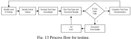
The strategy for system testing endeavors thoroughly testing the system, starting from the units, then to modules and finally the entire system itself. Fig. 13 shows the process flow.
Fig. 13 Process flow for testing.
integration testing was of separate units, hence they must be integrated together in conjunction to fulfill a specific task. This test is to ensure that the units that make up a module works appropriately, resulting the desired output.
Finally, system testing involved the system as a whole. This level of testing ensures that the modules works together to produce desirable outputs. Furthermore, testing at this stage ensures that the requirement specifications are met. Due to the limitation of space, the test cases and test results are not included in this paper. Basically, the test cases were into three categories; General, Mouse Mode and Sign Mode. The general test cases deal with the non-mode specific operations of the system. The other two categories deal with the operations of the system under the two modes as their name implies.
The test results of unit, integration, system testing as well as user acceptance testing produced favorable results. The testing for recognition accuracy revealed that the system's outstanding accuracy in classifying the gestures made under an optimum environment. In addition, the system does not only satisfy all of the functional and non-functional requirements, but was also generally well received by the users during the acceptance testing. Furthermore, in addition to working and performing its tasks, the system does so efficiently and without inconsistencies due to good design patterns, suitable algorithms and programming paradigm.
Next, a special testing will be done, in order to determine the accuracy of the system in terms of posture Next, a special testing will be done, in order to determine the accuracy of the system in terms of posture recognition. At the end, a user acceptance testing will be held.
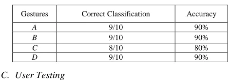
B. Recognition Accuracy
In testing the performance of the gesture recognition system, the system was evaluated under the ‘Sign’ mode. One of the non-functional requirements of the system is that the accuracy of the gesture recognition must be reasonably high under optimum lighting. Given four different gestures labeled from A to D, the number of correct prediction was recorded. Fig. 14 shows the gestures used to measure accuracy.
Fig. 14 Gesture A to D (Left to Right).
Finally, Table 2 shows the results for the recognition accuracy testing. The testing produced excellent results. The biggest contribution factors were due to the system operating under the optimum lighting and the background environment contrasted skin color, instead of resembling it. Regardless of which, this testing shows that the system has in fact satisfied the specified non-functional requirement.
TABLEII
RESULTS FOR RECOGNITION ACCURACY.
Gestures Correct Classification Accuracy
A 9/10 90%
B 9/10 90%
C 8/10 80%
D 9/10 90%
C. User Testing
Finally, user acceptance testing was carried out to ensure all user requirements are met by the system. This testing was also designed to collect users’ feedback on both functional and non-functional requirements of the system. Eight participants were randomly selected and asked to perform specific actions and their execution time and error rate were recorded. The test plan was divided into two sections; procedures dealing with the ‘Mouse’ mode 3 and the ‘Sign’ mode. The average results are shown in Table 3 and Table 4. Lastly, comments on various scenarios were compiled. Users were asked to comment on the system’s ability to select color spaces, to enable/disable background segmentation, to show/hide features, to display of video feedback via webcam, and to recognize gestures provided. Also, the user were asked to give general impression on the ‘Mouse’ mode, ‘Sign’ mode, as well as the overall response time. The responses from users were positive, where they noted that the controls are interesting, intuitive and natural as well as free from third party equipment.
TABLEIII
RESULTS FOR USER TESTING IN ‘MOUSE’ MODE.
Procedure Optimal
Execution Time
Optimal Error Rate (min)
Execution Time (sec)
Error Rate Result
Create new folder < 1 < 5 20 1 Satisfactory
Delete new folder < 1 < 5 45 4 Satisfactory
Open start menu < 1 < 5 10 0 Satisfactory
Close start menu < 1 < 5 5 0 Satisfactory
Open browser < 1 < 5 20 1 Satisfactory
Navigate to Google under booksmarks < 1 < 5 40 3 Satisfactory
Close browser < 1 < 5 30 2 Satisfactory
Open sample picture < 1 < 5 32 2 Satisfactory
Zoom in picture < 1 < 5 10 0 Satisfactory
Zoom out picture < 1 < 5 10 1 Satisfactory
TABLEIV
RESULTS FOR USER TESTING IN ‘SIGN’ MODE.
Procedure Optimal
Execution Time
Optimal Error Rate (min)
Execution Time (sec)
Error Rate Result
Enter full screen presentation mode in Microsoft power point presentation
< 10 < 5 5 1 Satisfactory
Navigate through sample presentation frontwards until the end
< 60 < 10 40 2 Satisfactory
Navigate through sample presentation backwards until the start
< 60 < 10 42 2 Satisfactory
Escape from full screen presentation mode < 10 < 5 5 0 Satisfactory
IV.CONCLUSION
The implementation of pseudo vision into the system provided insight as to how difficult and unforgiving the field is, with plenty variables and factors to take into account, and a large cache of algorithms to choose from, all of which has its specific usages and disadvantages to contemplate on. Efficiency, maintainability, upgradability, reusability and such are all highly dependent on the design of the system. Modularity is a highly sought after characteristic in a system, as it promotes low coupling which in turn results in all of the aforementioned benefits.
Each and every tool or technique used has been properly justified accordingly in regards to the requirements of the system, even the object oriented paradigm. Considering the complexity of the system, both in functionality and technicality, having the ability to divide the system into modules and subtasks helped tremendously. With the introduction of modularity and loose coupling, future updates and enhancements can be launched easily.
In conclusion, conventional input devices have indeed served humans well, however, as technology advances so does the need for a better interfacing. Current conventional input devices will continue to bottleneck this advancement in technology; therefore, a better alternative input technique should be looked into, in particularly, gesture-based input technique which offers user a more natural and intuitive control.
Although many users has voiced that the system is still not mature and ready to stand on its own as a well functional input device, but it is well on its way there. Despite its performance, this gesture-based recognition system can be further improved with the following enhancements.
• Depth. Instead of merely 2D processing, 3D processing can be implemented into the system for a more robust level of feature extraction and accurate representation of contour found. By introducing distance into the equation, many of image processing algorithms can be further implemented into the system; many different features of the hand can be further derived with the introduction of depth. Due to the design of the system, a depth processing module can be added into the design of the system without having too much of an effect on the entire system.
• Additional mouse mode – different features for different functions. At the moment, only one method of implementation of the mouse mode is made available. In order to further comply with the multiple situations that a user must face during interaction with a computer,
additional mouse modes can be implemented in order to introduce different feature-functions relations. Taking the design of the system into consideration, this additional support can be easily done by attaching new subclasses onto the Mouse class, hence making upgradability simple and easy.
• Additional support for sign mode. As with the mouse mode, the sign mode is currently tailor suited only for Microsoft Power Point. Additional support for different software given can be added easily by attaching new subclasses to the Command class. The ability to customize the commands each gesture sends can also be done to further increase the flexibility of the system. • Better background extraction algorithm. The
background subtraction algorithm used is currently sufficient for the requirements of the system. However, the algorithm can be made better with the inclusion of shadow removal and contour reconstruction. These inclusions will further preserve the authenticity of the contour.
In the future, given time and advancement in technologies, computer vision can be incorporated seamlessly into the interaction between man and machine, bridging the gulf of execution gap that even today, exists.
ACKNOWLEDGMENT
This paper has been supported in partial by Asia Pacific University Malaysia.
REFERENCES
[1] Nicu Sebe, Michael S Lew, and Thomas S Huang. The state-of-the-art in human-computer interaction. In International Workshop on Computer Vision in Human-Computer Interaction, pp. 1–6, 2004. [2] Don Norman. The design of everyday things: Revised and expanded
edition. Basic Books, 2013.
[3] Edwin L Hutchins, James D Hollan, and Donald A Norman. Direct manipulation interfaces. Human–Computer Interaction, 1(4):311– 338, 1985.
[4] Robert JK Jacob. Human-computer interaction: input devices. ACM Computing Surveys (CSUR), 28(1):177–179, 1996.
[5] On the horizon: A new remote catheter manipulation system, 2018. [6] NP Sheehy and AJ Chapman. Nonverbal behavior at the
human-computer interface. International Reviews of Ergonomics, 1:159–172, 1987.
[7] Alexander I Rudnicky, Alexander G Hauptmann, and Kai-Fu Lee. Survey of current speech technology. Communications of the ACM, 37(3):52–57, 1994.
[8] Russell Beale and ADN Edwards. Gestures and neural networks in human computer interaction. In Neural Nets in Human-Computer Interaction, IEE Colloquium on, pp. 5–1. IET, 2018.
[9] D Ward. Dasher with an eye-tracker, 2015.
speech recognition systems. In Proceedings of the SIGCHI conference on Human Factors in Computing Systems, pp. 568–575. ACM, 1999.
[11] I Scott MacKenzie, Abigail Sellen, and William A S Buxton. A comparison nof input devices in element pointing and dragging tasks. In Proceedings of the SIGCHI conference on Human factors in computing systems, pp.161–166. ACM, 1991.
[12] Alexander G Hauptmann. Speech and gestures for graphic image manipulation. In ACM SIGCHI Bulletin, volume 20, pp. 241–245. ACM, 1989.
[13] Dean Rubine. Specifying gestures by example, volume 25. ACM, 1991.
[14] Ramesh M Kagalkar and SV Gumaste. Detail study for sign language recognization techniques. Digital Image Processing, 8(3):65–69, 2016.
[15] Kouichi Murakami and Hitomi Taguchi. Gesture recognition using recurrent neural networks. In Proceedings of the SIGCHI conference on Human factors in computing systems, pp. 237–242, 1991. [16] Lam T Phi, Hung D Nguyen, TT Quyen Bui, and Thang T Vu. A
glove based gesture recognition system for Z Vietnamese sign language. In Control, Automation and Systems (ICCAS), 15th International Conference on, pp. 1555–1559, 2015.
[17] HS Nagendraswamy, BM Chethana Kumara, and R Lekha Chinmayi. Gist descriptors for sign language recognition: an approach based on symbolic representation. In International Conference on Mining Intelligence and Knowledge Exploration, pp. 103–114. Springer, 2015.
[18] Sidney Fels and Geoffrey E Hinton. Building adaptive interfaces with neural networks: The glove-talk pilot study. In Proceedings of the IFIPTC13 Third International Conference on Human-Computer Interaction, pp. 683–688, 1990.
[19] Philip J Mercurio, Thomas Erickson, D Diaper, D Gilmore, G Cockton, and B Shackel. Interactive scientific visualization: An assessment of a virtual reality system. In INTERACT, pp. 741–745, 1990.
[20] Thomas G Zimmerman, Jaron Lanier, Chuck Blanchard, Steve Bryson, and Young Harvill. A hand gesture interface device. In ACM SIGCHI Bulletin, volume 18, pp. 189–192. ACM, 1987.
[21] Andrew D Wilson and Edward Cutrell. Flowmouse: A computer vision-based pointing and gesture input device. In INTERACT, vol. 5, pp.565–578, 2005.
[22] Randy Pausch. Virtual reality on five dollars a day. In Proceedings of the SIGCHI Conference on Human Factors in Computing Systems, pp. 265–270, 1991.
[23] Eric J Townsend. Mattel Power Glove FAQ, 1993.
[24] Jane J Stephan and Sana’a Khudayer. Gesture recognition for human computer interaction (HCI). Int. J. Adv. Comp. Techn., 2(4):30–35, 2010.
[25] Zhang Lei, Zhang Xue-fei, and Liu Yin-ping. Research of the real-time detection of traffic flow based on open CV. In Computer Science and Software Engineering, International Conference on, volume 2, pp. 870–873. IEEE, 2008.
[26] James Kerr and Richard Hunter. Inside RAD: How to build fully functional computer systems in 90 days or less. McGraw-Hill, Inc., 1994.
[27] Li, C., Xie, C., Zhang, B., Chen, C. and Han, J., 2018. Deep Fisher discriminant learning for mobile hand gesture recognition. Pattern Recognition, 77, pp.276-288.
[28] Wu, Y., Jiang, D., Duan, J., Liu, X., Bayford, R. and Demosthenous, A., 2018, May. Towards a High Accuracy Wearable Hand Gesture Recognition System Using EIT. In Circuits and Systems (ISCAS), 2018 IEEE International Symposium on (pp. 1-4). IEEE.
[29] Núñez, J.C., Cabido, R., Pantrigo, J.J., Montemayor, A.S. and Vélez, J.F., 2018. Convolutional Neural Networks and Long Short-Term Memory for skeleton-based human activity and hand gesture recognition. Pattern Recognition, 76, pp.80-94.
[30] Patel, N.A. and Patel, S.J., 2018. A Survey On Hand Gesture Recognition System For Human Computer Interaction (HCI). [31] Antoshchuk, S., Kovalenko, M. and Sieck, J., 2018. Gesture
Recognition-Based Human–Computer Interaction Interface for Multimedia Applications. In Digitisation of Culture: Namibian and International Perspectives (pp. 269-286). Springer, Singapore. [32] Rafii, A., Gokturk, S.B., Tomasi, C. and Sürücü, F., Microsoft