IMPROVING THE TRANSIENT STABILITY OF THE NIGERIA 330KV TRANSMISSION
GRID USING THYRISTOR CONTROLLED SERIES COMPENSATOR
I. K. Okakwu
1,*, E. A. Ogujor
2and P. E. Orukpe
31, 2, 3,,
D
EPT.
OFE
LECTRICAL/E
LECTRONICE
NGINEERING,
U
NIVERSITY OFB
ENIN,
B
ENINC
ITY,
E
DOS
TATE.
NIGERIA
E-mail addresses:
1[email protected],
2[email protected],
3[email protected]
ABSTRACT
This study reveals the transient stability improvement capability of Thyristor Controlled Series Compensation (TCSC) as an effective Flexible AC Transmission System (FACTS) device in damping low frequency oscillations on the Nigeria 330kV transmission system. The study was performed using commercially available MATLAB software. The analysis was carried out by simulating a 3-phase fault on the network in order to determine the Critical Clearing Time (CCT) of the system. In locating the TCSC, the most severely disturbed generator was considered. Simulation results on the Nigeria 330kV transmission system modelled in MATLAB environment reveals appreciable transient stability enhancement of the network.
Keywords: transient stability, critical clearing time, thyristor-controlled series compensator, 3-phase fault, Nigerian 330kV transmission system
1. INTRODUCTION
In the last few years, the power system interconnected network has become more complex and difficult to manage due to increase in load demand which has forced electric utilities to either operate the system beyond or close to their thermal stability limit [1]. This development of operating the system close to its limit will definitely have a negative effect on the system security [2]. Security of power system refers to its ability to withstand disturbances without losing synchronism. One of the measures to ascertain system security is the transient stability [3]. Transient stability of a power system is the ability of the power system to still maintain equilibrium after being subjected to disturbance [4]. The robustness of a power system is determined by its critical clearing time (CCT) value. CCT is the fault clearing time for the system to remain stable [5], a larger value of CCT denotes a better secured power system [6].
One of the ways to increase the CCT of a Power System is the use of Flexible AC Transmission Systems (FACTS), which has proven to be cost effective compared to construction of new transmission lines [7]. FACTS devices are power electronic based instruments that has the ability to control the network condition in a very fast manner and this unique ability can be utilized to improve transient stability of a power
system [8]. The detailed explanation about FACTS devices can be found in the literature [9-10]. Different FACTS controllers have been proposed for enhancing power system stability which includes Static Var Compensator (SVC), Thyristor Controlled Series Compensator (TCSC), Static Synchronous Series Compensator (SSSC), Static Synchronous Compensator (STATCOM), Unified Power Flow Controller (UPFC), etc. Among all the FACTS families, TCSC is one of the most preferred series compensator in terms of improving transient of power system [11]. The TCSC ability to operate in different modes results in more power transfer, which invariably leads to improvement in system stability [12]. Furthermore, the extensive literature review projects TCSC as the most effective in terms of transient stability enhancement compared to other FACTS devices [13]. TCSC is a series compensator connected in series with the lines to be compensated [14]. It allows continuous and rapid changing of transmission line impedance, thereby improving system stability [15].
The Nigeria 330kV transmission network is be-deviled with series of challenges due to its long radial nature, weak transmission network and overloaded lines [16]. Various studies have been done on the Nigerian 330kV network by different indigenous researchers. In [17], the authors did a performance comparison on the effect
Vol. 37, No. 4, October 2018, pp.
1092 – 1098
Copyright© Faculty of Engineering, University of Nigeria, Nsukka,
Print ISSN: 0331-8443, Electronic ISSN: 2467-8821
www.nijotech.com
of Power system stabilizer (PSS) and STATCOM in damping oscillations on the Nigeria 330kV North-Central network. The placement of STATCOM was optimally done using Genetic Algorithm (GA), whereas that of PSS was determined using eigenvalue analysis. The result reveals that STATCOM has a more pronounced positive effect in damping oscillation than PSS. In [18], the authors explored the use of TCSC in reducing real power losses of the Nigeria 330kV transmission grid. GA optimization technique was used to optimally locate the TCSC on the Nigeria 330kV grid. The result obtained shows a reduction of active power losses from the initial 2.1% to 1.5%. The authors in [19] considered the use of Interline Power Flow Controller (IPFC) in improving the voltage profile of weak buses in the Nigeria 330kV network. GA optimization technique was used for optimal placement of the IPFC. Their result reveals the importance of the use of FACTS devices in the Nigerian 330kV transmission grid. In [20], the authors compared the use of STATCOM and SSSC for voltage profile enhancement and loss reduction on the Nigeria 330kV
transmission network. The result obtained from the incorporation of these devices shows that the voltage magnitude of the buses was improved to the satisfactory voltage magnitude (1.05pu-0.95pu), while the real and reactive power losses were reduced by 0.171% and 1.009% when STATCOM was incorporated, 1.078% and 10.33% with SSSC. Most of the studies carried out on the Nigeria 330kV transmission network were majorly focused on either voltage profile improvement or loss reduction. This paper is aimed at investigating the effect of TCSC on transient stability of the Nigerian 330kV transmission network using MATLAB/SIMULINK Software.
2. STRUCTURE OF THE NIGERIAN 330kV TRANSMISSION NETWORK
Figure 1 depicts the single line diagram of the Nigerian 330kV Transmission network used in this study. It consists of 11 generating stations, 21 load buses, 36 transmission lines and 32 buses [21]. The total installed capacity is approximately 5,000MW with 5,524km lines.
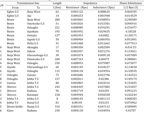
Table 1: Nigerian 330-kV Transmission Line Parameters
S/N Transmission line Length Impedance Shunt Admittance
From To L(km) Resistance (Rpu) Inductance (Xpu) 1/2 Bpu (S)
1 Egbin G.S Ikeja West 62 0.001122 0.008625 0.064345
2 Egbin G.S Aja 14 0.000253 0.001948 0.014529
3 Benin Ikeja West 280 0.005065 0.038953 0.290589
4 Benin Omotosho G.S 51 0.001826 0.015501 0.096916
5 Benin Oshogbo 251 0.008989 0.076291 0.476977
6 Benin Ajaokuta 195 0.003492 0.029635 0.18528
7 Benin Onitsha 137 0.002453 0.02082 0.130171
8 Benin Sapele G.S 50 0.000904 0.006956 0.051891
9 Benin Delta G.S 41 0.001468 0.012462 0.077913
10 Ikeja West Akangba 17 0.000304 0.002584 0.016`53
11 Ikeja West Sakete 70 0.002507 0.021276 0.133021
12 Ikeja West Olorunshogo G.S 30 0.001074 0.009118 0.057009
13 Ikeja West Omotosho G.S 200 0.007163 0.06079 0.380061
14 Ikeja West Oshogbo 250 0.008953 0.075987 0.475077
15 Aiyede Olorunshogo G.S 60 0.002149 0.018237 0.114018
16 Aiyede Oshogbo 115 0.004118 0.034954 0.218535
17 Oshogbo Ganmo 75 0.002686 0.022796 0.142523
18 Oshogbo Jebba T.S 157 0.002811 0.02386 0.149174
19 Ganmo Jebba T.S 80 0.002865 0.024316 0.152025
20 Shiroro Jebba T.S 244 0.004369 0.037082 0.231837
21 Shiroro Kaduna 96 0.001719 0.01459 0.091215
22 Shiroro Katampe 218 0.003944 0.030328 0.226244
23 Jebba T.S Jebba G.S 8 0.000145 0.001113 0.008303
24 Jebba T.S Kainji G.S 81 0.00145 0.01231 0.076962
25 Birnin Kebbi Kainji G.S 310 0.005551 0.047112 0.589095
S/N Transmission line Length Impedance Shunt Admittance
From To L(km) Resistance (Rpu) Inductance (Xpu) 1/2 Bpu (S)
27 Kaduna Jos 196 0.00351 0.029787 0.37246
28 Jos Gombe 264 0.004727 0.040121 0.501681
29 Gombe Yola 240 0.004298 0.036474 0.456074
30 Ajaokuta Geregu G.S 1 0.000018 0.000139 0.001038
31 Onitsha Alaoji 138 0.004942 0.041945 0.262242
32 Onitsha New Haven 96 0.003438 0.029179 0.182429
33 Onitsha Okpai G.S 60 0.001085 0.008347 0.062269
34 Alaoji Afam G.S 25 0.000452 0.003478 0.025945
35 Sapele G.S Aladja 63 0.002256 0.019149 0.119719
36 Delta G.S Aladja 32 0.001146 0.009726 0.06081
Fig 1: Single Line Diagram of the Nigeria 330-kV transmission [21]
3. MATHEMATICAL MODELLING
3.1 Multi-Machine Modelling of Power System
The rotor dynamics representing swing equation is given by equation (1) [22].
n
k
P
P
dt
d
M
k mi eik 2
1
,
2
(1)
where, M = angular momentum (J-sec/rad); Pm= shaft power input (W); Pe= electrical power output (W); δ=
angular displacement (rad). The electrical Power output of each generator is given by [23].
k j k j
k j j m
k k k k
k k k
ek E Y E E Y Cos
P
1 2
cos
(2)
The rotor dynamics representing the swing equation of generator k is given by
ek mk k
o
k
P
P
dt
d
f
H
2 2
(3)Kainji B-Kebbi
Jebba GS Jebba TS
Shiroro
Yola Jos Gombe
Kano Kaduna
Ganmo
Geregu Katampe
Oshogbo Aiyede
Sapele
Egbin
Benin Ajaokuta
Onitsha
New Heaven
Olorunsogo Alaoji
Aladja Afam
Okpai Omotosho
Ikeja West
Akangba
Therefore, the swing equation for during-fault and post-fault are expressed by equations (4) and (5) respectively. ) ( 2 2 fault during ek mk k o
k
P
P
dt
d
f
H
(4) ) ( 2 2 fault post ek mk k ok
P
P
dt
d
f
H
(5)Table 1: Impedance characteristics of TCSC
Range of firing angle Operating region
90oLlim Inductive region
Llim c lim Resonance region
clim 180o Capacitive region
Table 2: Bus nomenclature
Bus No Bus Name Bus No Bus Name
1 Egbin G.S 17 Kaduna
2 Benin 18 Jos
3 Ikeja West 19 Gombe
4 Akangba 20 Yola
5 Sakete 21 Katampe
6 Aiyede 22 Ajaokuta
7 Olorunshogo G.S 23 Geregu G.S
8 Omotosho G.S 24 Onitsha
9 Oshogbo 25 Alaoji
10 Ganmo 26 New Haven
11 Shiroro G.S 27 Sapele G.s
12 Jebba T.S 28 Delta G.S
13 Jebba G.S 29 Okpai G.S
14 Birnin Kebbi 30 Afam G.S
15 Kainji G.S 31 Aja
16 Kano 32 Aladja
3.2 Modelling TCSC
The TCSC is a series type reactive power compensator, which consists of a series capacitor bank, shunted by a thyristor-controlled reactor. It is connected in series with the transmission line where it is located [24]. Figure 2 depicts the single line diagram of a TCSC.
TCSC can be controlled by changing the firing angle (α) of the thyristor which modifies the frequency of the capacitor [26]. Equation (6) shows the relationship between the firing angle of the thyristor (α) and the reactance (XTCSC):
) 2 / tan( ) 2 / tan( ( ) 1 ( ) 2 / ( ) ( 4 ) ( 2 2 2 2 ) ( K K K Cos X X X Sin X X X X X p c c p c c c TCSC (6)
where, XC = Capacitance of the capacitor; XP = Inductive reactance of the reactor;
= 2(π-α) = Conductionangle of TCSC controller; K=
p c
X
X
= Compensationratio.
The TCSC is operated here in the capacitive mode for transient stability enhancement [27]. Figure 3 and Table 1 shows the impedance characteristics of TCSC.
Fig 2: Basic Circuit diagram of TCSC [25]
Fig 3: Impedance characteristic of TCSC [27]
Consequently, to avoid over compensation of transmission line, the working range of XTCSC is chosen from -70% Xline to 20% Xline [28].
ine l TCSC
TCSC
r
X
X
(7)TCSC old
line new
line
X
X
X
( )
( )
(8)With -70% compensation of line (Xline(old))), i.e.
r
TCSC=0.0024346pu; Xline(old) = 0.003478pu and Xline(new) = 0.0010434pu; where,
r
TCSC= Compensation Factor;Xline(old)= line reactance before compensation; Xline(new)= line reactance after compensation.
3. RESULTS AND DISCUSSION
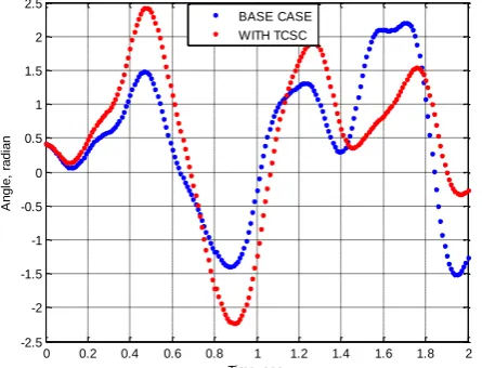
To assess the effectiveness of the TCSC, simulation was done using the most severe fault (3-phase fault) and the most severely disturbed generator (Afam generating station) for transient stability enhancement. The
dynamic responses of the generator are shown in Figures 4 – 9 when a 3-phase fault is applied at Aiyede bus.
Fig 4 : Swing curve of generator at Afam with Line 6-7 removed (CCT = 800ms)
Fig 5 : Swing curve of generator at Afam with Line 6-7 removed (CCT = 810ms)
Fig 6 : Swing curve of generator at Afam with Line 6-7
removed (CCT = 820ms) Fig 7 : Swing curve of generator at Afam with Line 6-7 removed (CCT = 830ms)
Fig 8 : Swing curve of generator at Afam with Line 6-7 removed (CCT = 840ms)
Fig 9 : Swing curve of generator at Afam with Line 6-7 removed (CCT = 850ms)
0 0.2 0.4 0.6 0.8 1 1.2 1.4 1.6 1.8 2 -2.5
-2 -1.5 -1 -0.5 0 0.5 1 1.5 2 2.5
Time, sec
A
n
g
le
,
ra
d
ia
n
BASE CASE WITH TCSC
0 0.2 0.4 0.6 0.8 1 1.2 1.4 1.6 1.8 2 -2.5
-2 -1.5 -1 -0.5 0 0.5 1 1.5 2 2.5
Time, sec
A
n
g
le
,
ra
d
ia
n
BASE CASE WITH TCSC
0 0.2 0.4 0.6 0.8 1 1.2 1.4 1.6 1.8 2 -3
-2 -1 0 1 2 3
Time, sec
A
n
g
le
,
ra
d
ia
n
BASE CASE WITH TCSC
0 0.2 0.4 0.6 0.8 1 1.2 1.4 1.6 1.8 2 -3
-2 -1 0 1 2 3 4
Time, sec
A
n
g
le
,
ra
d
ia
n
BASE CASE WITH TCSC
0 0.2 0.4 0.6 0.8 1 1.2 1.4 1.6 1.8 2 -3
-2 -1 0 1 2 3 4
Time, sec
A
n
g
le
,
ra
d
ia
n
BASE CASE WITH TCSC
0 0.2 0.4 0.6 0.8 1 1.2 1.4 1.6 1.8 2 -3
-2 -1 0 1 2 3 4 5 6
Time, sec
A
n
g
le
,
ra
d
ia
n
At a CCT of 800ms to 840ms (Figures 4 to 8), the dynamic responses of the generator with and without TCSC were stable, i.e. without losing synchronism. When the CCT was increased to 850ms, the swing curve without TCSC loses synchronism, while the one with TCSC still remained stable. Hence, the dynamic response of the generator at a CCT of 850ms clearly depicts that the proposed TCSC controller can damp power system oscillations better than a system without TCSC.
4. CONCLUSION
In this paper, investigation on the use of TCSC in enhancing transient stability of the Nigeria 330kV transmission network was carried out. The swing curve for the network was obtained, from which the transient stability analysis was done. The result shows that with a 3-phase fault on Aiyede bus, the generating station at Afam loses synchronism at a CCT of 850ms. Hence, for the system to remain stable, the fault must be cleared at a CCT of 840ms. But with the incorporation of TCSC into the network, the system was able to withstand a 3-phase fault even beyond a CCT of 850ms. The result therefore signifies the effectiveness of TCSC controller in improving the CCT of the System without losing synchronism when a 3-phase fault occurs.
5. REFERENCES
[1] Khoshnaw, K.H. and Saleh, E.E. “Transient stability improvement in Multi-Machine System using Power System Stabilizer (PSS) and Static Var Compensation (SVC)”, International Journal of Electrical, Computer, Energetic, Electronic and Communication Engineering, 9, 1362-1374, 2005.
[2] Ayodele, T.R., Ogunjuyigbe, A.S.O. and Oladele, O.O. “Improving the Transient stability of Nigerian 330kV Transmission network using SVC”, Nigerian Journal of Technology, 35, 155-166, 2016.
[3] Ayodele, T. R., Jimoh, A. A., Munda, J. L. and Agee, J. T. “The impact of wind power on power system transient stability based on probabilistic weighting method”, Journal of Renewable and Sustainable Energy, 4, 1-18, 2012.
[4] Adepoju, G.A. and Tijani, M.A, “Critical Clearing time evaluation of Nigerian 330kV transmission system”, American Journal of Electrical Power and Energy Systems, 2, 123-128, 2013.
[5] Oluseyi, P.O., Adelaja, T.S. and Akinbulire, T.O. “Analysis of the Transient stability limit of the Nigeria 330kV Transmission Sub-network”,
Nigerian Journal of Technology, 36, 213-226, 2017.
[6] Abhijit, C. and Sunita, H. “Power System Analysis, Operation and Control”, New Delhi, Third Edition, 2010.
[7] Hussain, A., Amin, M., Khan, R.D. and Chaudhry, F.A. (2018). “Optimal allocation of FACTS Controllers in Electric Power network”, Indian National Academy of Engineering, Vol. 3; 41-64.
[8] Kumar, S. and Kumar, N. “Effectiveness of FACTS devices for power system stability enhancement”,
International Journal of Advances in Engineering Sciences, Vol. 1; 1-4, 2011.
[9] Hingorani, N.G. and Gyugyi, L.. “Understanding FACTS: Concepts and Technology of Flexible AC Transmission System. IEEE Press, 2000.
[10] Song, Y.H. and John, T.A. “Flexible AC Transmission System (FACTS), IEE London, 2000.
[11] Mahapure, P.S. and Soman, A.R. “Comparison of FACTS devices for power system transient stability improvement”, International Journal of Innovative Research in Electrical, Electronic, Instrumentation and Control Engineering, Vol. 2; 1599-1602, 2014.
[12] Dixit, S., Srivastava, L., Singh, A. and Agnihotri, G. “Optimal Placement of TCSC for enhancement of power system stability using Heuristic method: An Overview”, International Journal of Hybrid Information Technology, Vol. 8; 367-374, 2015.
[13] Abido, M. A. “Power system stability enhancement using FACTS Controllers: A Review”, The Arabian Journal for Science and Engineering, Vol. 34; 153-172, 2009.
[14] Yarlagadda, V., Ram, B.V.S. and Rao, K.R.M. “Automatic control of Thyristor Controlled Series Capacitor”, International Journal of Engineering Research and Application, Vol. 2; 444-449, 2012.
[15] Kumar, A. and Dubey, S.B. “Enhancement of transient stability in transmission line using SVC FACTS Controller”, International Journal of Recent Technology and Engineering, Vol. 2; 51-56, 2013.
[16] Adebayo, A.A., Osho, S.O. and Yusuf, B.M. “National development and security challenges”, Proceedings of 8th Engineering Forum, School of Engineering, Federal Polytechnic, Ado-Ekiti, Nigeria; 1-4, 2011.
[17] Ambafi, J.G., Nwohu, M.N., Ohize, H.O. and Tola, O.J. “Performance Evaluation of PSS and STATCOM on Oscillation damping of a North-Central Power Network of Nigeria Grid System”, International Journal of Engineering and Technology, 2, 209-218, 2012.
[18] Nwohu, M.N., Isah, A., Usman, A.U. and Sadiq, A. A., “Optimal placement of Thyristor Controlled Series Compensator (TCSC) on Nigerian 330kV transmission grid to minimize real power losses”,
Electrical and Electronics Engineering, 2, 18-26, 2016.
[19] Omorogiuwa, E. and Onohaebi, S.O. “Optimal location of IPFC in Nigeria 330kV integrated power network using GA technique”, Journal of Electrical and Electronic System, 4, 1-8, 2015.
[20] Aborisade, D.O., Adebayo, I.G. and Oyesina, K.A. “A Comparison of the Voltage Enhancement and loss reduction capabilities of STATCOM and SSSC FACTS Controllers”, American Journal of Engineering Research, 3, 96-105, 2014.
[21] Okakwu, I.G. and Ogujor, E. A., “Enhancement of transient stability of the Nigeria 330kV Transmission Network using Fault Current Limiter”, Journal of Power and Energy Engineering, 5, 92-103, 2017.
[22] Gupta, K. and Pandey, A. “Stabilization of Multi-Machine System Connected to Infinite Bus”,
International Journal of Scientific and Technology Research, 2, 82-85, 2013.
[23] Vishnoi, U. and Sharma, B. “Stability analysis of Multi-Machine SMIB System”, International Journal of Science, Engineering and Technology, 3, 88-93, 2015.
[24] Hassan, H.T., Malik U.F., Khan I.A. and Khalid, T, “Stability improvement of power system using
Thyristor Controlled Series Capacitor (TCSC)”,
International Journal of Engineering and Computer Science, 13, 30-34, 2013.
[25] Sangheetha, A.P. and Padma, S. “Study of Thyristor Controlled Series Compensator for the enhancement of power flow and stability”,
International Journal of Scientific and Engineering Research, 5, 112-117, 2014.
[26] Conka, Z., Kolcun, M., Kolcun M.J., Dudiak, J., Mikita, M. and Vojtek, M. (2016), “Improvement of power system stability using FACTS device”, Journal of Power and Electrical Engineering, 33, 12-15, 2016.
[27] Vaibhav, D., Vivek, P. and Anilkumar, M. “Enhancement of Transient Stability of Power System with Variable series compensation”,
International Journal of Engineering Research and Development, 2, 62-68, 2015.
[28] Kumar, N.M.G., Venkatesh, P. and Raju, P.S., “Modelling and Analysis of SVC, TCSC, TCPAR in power flow studies”, International Journal of
Engineering Technology and Advanced
Engineering, 3, 418-425, 2013.
[29] Okakwu, I. K. and Ogujor, E. A. “Transient Stability of the Nigerian 330kV transmission network”,
![Fig 1: Single Line Diagram of the Nigeria 330-kV transmission [21]](https://thumb-us.123doks.com/thumbv2/123dok_us/10000546.1987592/3.595.57.513.250.615/fig-single-line-diagram-of-the-nigeria-transmission.webp)
![Fig 2: Basic Circuit diagram of TCSC [25]](https://thumb-us.123doks.com/thumbv2/123dok_us/10000546.1987592/4.595.304.528.210.496/fig-basic-circuit-diagram-tcsc.webp)