Handoff Mechanism in Real Time Applications Using
Two Different Algorithms
Vicky Kumar
M.Tech (ECE) Scholar
Lovely Professional University (LPU), Phagwara [email protected]
Abstract — This paper proposes an extension of Session Initiation Protocol (SIP) to support soft handover with bicasting and buffering, named mobile SIP (mSIP). In the mSIP scheme, the soft handover is achieved by bicasting and buffering to the mobile node in the handover region. For this purpose, a new handover’ header is defined in the SIP re -INVITE message. The mSIP handover can reduce handover latency and loss, compared to the SIP handover.
Keywords - handoff, SIP, mSIP.
I. I
NTRODUCTIONThe SIP is used for control of real-time multimedia sessions. It can also be used to support a variety of Internet mobility. This Letter will focus on the SIP based IP handover for terminal mobility. In the existing SIP handover, a mobile node (MN) performs IP handover by sending another INVITE (called re-INVITE) method to the correspondent node (CN) after getting a new IP address. This SIP handover tends to give a large handover latency associated with movement detection and IP address configuration [3]. This is mainly because the SIP handover cannot effectively support the ‘soft’ handover. This Letter proposes an extension of SIP to support soft handover with ‘bicasting and buffering’. A recent work on SIP-based bicasting proposed to use a network agent named ‘Handover Assisted Server (HOAS)’ for bicasting, which is located in the network between MN and CN. However, this Letter will consider an ‘end-to-end’ bicasting between MN and CN without using any network agent. In the proposed mSIP scheme, MN will communicate with CN using bicasting over two IP addresses in the handover region.
II. M
SIPD
ORS
OFTH
ANDOVERA. Existing SIP Handover
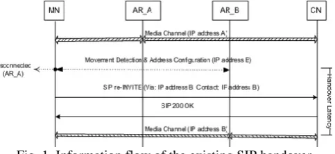
We first describe the existing SIP handover, as depicted in Figure 1. In the AR A region, MN is communicating with CN by using IP address A. As it moves into AR B region, the media channel with IP address A will be disconnected. MN then begins movement detection and address configuration. After getting a new IP address, MN sends an SIP re-INVITE method, which contains the new IP address, and receives the SIP 200 OK from CN. During this handover period, MN cannot receive the media stream from CN, which induces the concerned handover latency. In the
figure the SIP ACK method is not shown, since it does not affect the handover latency.
Fig. 1. Information flow of the existing SIP handover
B. New Headers for mSIP Handover
The mSIP handover is designed to support ‘bicasting’ of media streams from CN to MN during handover. For this purpose, we define a new SIP ‘handover’ header, as follows: Handover: add | del;ip=a.b.c.d
This new header will be inserted into SIP re-INVITE method. This header instructs CN to add or delete the IP address indicated (a.b.c.d) to or from the associated tables used for SIP signaling and media streams. In particular, the ‘add’ flag will inform CN to start bicasting to MN (with IP address indicated), in which CN will duplicate and transmits the identical media streams to MN. On the other hand, the ‘del’ flag instructs the CN to stop bicasting (i.e., transmission over the old IP address). For backward compatibility with the current SIP protocol, the re-INVITE message may include the ‘require’ header in the form of “Require: handover.” If the CN cannot support the mSIP handover (i.e., handover header), it will respond to MN with “420 (Bad Extension)”. Inthis case, MN may try to perform the exiting SIP handover, as described earlier. It is noted in the mSIP handover that the re-INVITE message also contains the associated Session Description Protocol (SDP) information in the message body so as to describe the characteristics of the media channels associated with handover, as specified in the RFC 3261 .
C. Algorithm of mSIP Handover using Bicasting
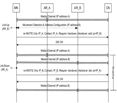
the soft handover with bicasting. The proposed mSIP handover procedures are illustrated in Figure 2.
In the figure, MN initially uses IP address A (IP A). When it moves into AR B region, it will detect a Link-Up for AR_B.It then performs movement detection and obtains a new IP address (IP B) via DHCP or IPv6 address auto-configuration. After getting a new IP address, MN sends an SIP re-INVITE method which contains the information on IP B and handover header, as specified in the figure. CN will respond with SIP OK message to MN. Since then, CN can transmit an identical media stream to MN over both IP A and IP_ B. That is, CN starts bicasting to MN. In this period, MN transmits its own media stream to CN using either IP A or IP_ B. As MN further moves into the AR_ B region, it will detect the Link-Down event for AR_ A. MN then sends an SIP re-INVITE message to CN, as specified in the figure, so as to stop bicasting (i.e., transmission over IP address A). After the corresponding OK message is received, MN and CN use only the IP_ B address. It is noted that the proposed mSIP handover can be applied to horizontal handover (MN with a single network interface) as well as vertical handover (MN with two or more network interfaces). In the vertical handover, MN can receive duplicated data streams bicast by CN via its two network interfaces (AR_A and AR_B). In case of horizontal handover,MN will ‘actually’ receive only one data stream via its single network interface (AR A or AR B), even though CN bicasts data packets to MN. Even in this case, the mSIP scheme can reduce the probability of handover losses with the help of bicasting.
Fig. 2. Information flow of mSIP handover with bicasting.
d. Algorithm of mSIP Handover using buffering
technique
The handoff procedure in an SIP-based wireless network consists of three steps, namely, data link layer handoff, network layer handoff, and application layer handoff. This
is shown in Fig. 2. Data link layer handoff delay (TL2) refers to the time duration that it took to select an access point to reassociate by active scanning. Network layer handoff delay (TL3) is the amount of time taken in acquiring an IP address using Dynamic Host Configuration Protocol (DHCP) in a visited network, while application layer handoff delay (TAP) is the amount of time taken in the processing of the SIP re- INVITE packet.The time of Thandoffis defined as,
T
handoff =T
L2+T
L3+T
AP (1)During the Thandoff, the mobile host cannot send or receive any packet. In this paper, we integrate the multicast, and buffering technique to reduce the impact of the Thandoff for multimedia streaming services
We have a playout buffer which absorbs the affect of delay jitter to provide a smooth real-time streaming playback. The playout buffer stores enough data before the on-demand multimedia beginning playout .
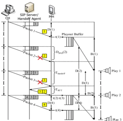
Fig. 3. The operation procedure of the buffering scheme Figure 4 illustrates the playout buffer operations. We assume there is MP3 music encoded in constant bit rate (CBR) on the demand service in CH. The packet interval generated by CH is I. The symbol D(i) stands for the end-to-end packet delay from CH to MH for the ith packet. The timemof the ith packet arriving in MH is denoted as t(i). The time of the ith packet waiting in the playout buffer for the playout is represented as B(i).
As shown in Fig. 4, the relationship between the arrival time and waiting time of the packet in the playout buffer can be represented as
t(i) + B(i) = t(1) + B(1) =+(i =1)I B(i) = t(1) =+B(1) = (i =1)I - t(i) (2)
Fig. 4. Illustration of playout buffer operations If the value of B(i) is positive, we are assured that there are multimedia data in the playout buffer. Thus,
B(1)>D(i)-D(1) (4) Given that the jitter J is defined as,
J = Max|D(i)–D(j)| (5)
If B(1) > J, then Eq. (4) also holds. Thus, if the initialized buffering delay B(1) exceeds the network jitter J, we can prevent the playout buffer underflow.
In addition to the packet jitter, Fig. 5 considers the handoff operations with caching and multicast technology in the Handoff Agent. When we consider the metric of handoff latency, the packet delay D(i) in the worst case will be,
D(i)=Dprop(i) + Thandoff+TRTT (6)
Fig. 5. Illustration of the playout buffer with handoff consideration
where Dprop(i) is the propagation delay time of the ith
packet from CN to MH without occurring handoff, and TRTT is the time from MH issuance of a multicast request to receipt of MH of the multicast packets generated by the Handoff Agent. Thus, the Eq. (4) can be rewritten as
B(1) > Dprop(i) + Thandoff+TRTT + D(1) B(1) > J + Thandoff+TRTT (7)
If B(1) confines the inequality Eq. (7), we can prevent theplayout buffer underflow during streaming transmission. When considering Eq. (1), the handoff delay Thandoff has been reduced to TL2. Thus, Eq. (7) can be rewritten as
B(1) > J + TL2+ TRTT
The minimum playout buffer in MH and minimum buffer size in the Handoff Agent is,
(J + TL2+ TRTT) * V
where V is the media stream rate. And TL2 is the data link layer hand off delay time. The buffer is used to caching the loss packet during handoff processes. When the Handoff Agent receives the multicast request packet from MH, the entire stored data packet in the buffer is retransmitted with multicast to MH in burst in order to recover the lost packets.
III. I
MPLEMENTATIONA Implementation System for Broadcasting
In the application point of view, MN will receive the duplicated media streams from CN in the bicasting period. In this case, MN’s application shall select only one of the received two media streams and then discard the other stream. For example, an MN may prefer the media data delivered received from the new IP address to the one received from the old IP address. In the viewpoint of SIP signaling path, the re-INVITE message with add flag is transmitted over the old IP address, whereas the re-INVITE message with del flag may be delivered over the new IP address. Accordingly, when the CN receives the re-INVITE with add flag, it shall bind its SIP signaling channel to the new IP address as well as the old IP address. After the re-INVITE message with del flag is received, the CN can release the old IP address from its SIP signaling channel.
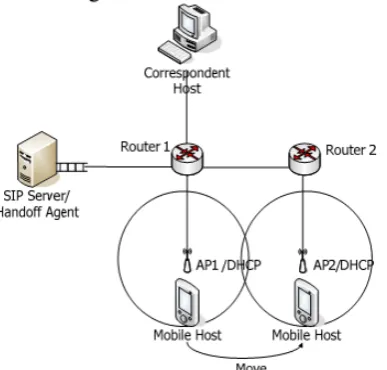
B Implementation System for Buffering
music, MH moves from the signal covered area of AP1 to AP2.
Fig. 6. System Implementation environments.
IV. P
ERFORMANCEA
NALYSIS ANDE
XPERIMENTALR
ESULTA. Performance analysis and Experimental results
for broadcasting
The handover performance can be measured as handover loss and latency. It is clear that the mSIP handover can reduce the handover loss probability, compared to the SIP handover, with the help of bicasting. In this section, we will analyze the handover latency taken for SIP handover and mSIP handover. The handover latency of SIP handover (TSIP HO) can be calculated as:
TSIP_ HO=TMD+TAC+TSIP
In the equation, TMD represents the movement detection (MD) delay taken for MN to detect its movement in the new subnet, TAC is the address configuration (AC) delay required for configuration of a new IP address via DHCP or stateless address auto-configuration, and TSIP is for the delay of exchanging the SIP re-INVITE and OK messages. It is noted that the TMD and TAC will depend on the MD and AC schemes employed in the network, whereas TSIP is equal to the round trip time (RTT) between MN and CN. In case of mSIP handover, the MN performs the handover in the handover (overlapping) region that is located between the two concerned networks. In the handover region, MN can still receive the media streams from CN using bicasting, even when the MD and AC operations are performed. Accordingly, the mSIP handover latency is equal to only the delay taken for MN to exchange the SIP re-INVITE and OK messages with CN. Then, the mSIP handover latency (TmSIP HO) can be summarized as:
TSIP_ HO= TSIP
Fig.7. Sojourn time of MN in the handover region
In fact, the mSIP handover latency in the real networks will depend on the sojourn time of MN in the handover region, as shown in Fig 3. As shown in the figure, if the sojourn time of MN in the handover region is less than TMD +TAC, the mSIP handover latency may increase up to the
TMD + TAC + TSIP, which is equal to the handover latency
of the existing SIP handover. In the meantime, only if the sojourn time in the handover region is large enough to complete the MD and AC operations, the mSIP handover latency can be reduced to only TSIP . Such a performance gain comes because the mSIP handover can enable MN to receive the media streams from CN using bicasting even during the handover.
B.
Performance analysis and Experimental Results
for Buffering Technique
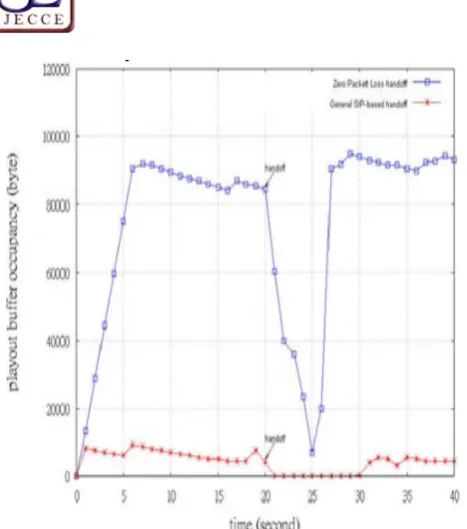
Fig. 7. Comparison of playout buffer occupancy between the proposed scheme and the general SIP-based scheme
It must be noted that the Handoff Agent buffers the loss packets and bursts forward to MH when MH completes the layer 2 handoff. There is no packet loss in the proposed scheme. The received packet sequence number runs continuously all the time.
V. C
ONCLUSIONSeamless mobility is an important paradigm for uninterrupted services in ubiquitous network environments. In this paper, a lossless handoff scheme supported by the bicasting scheme, caching, and buffering is proposed for SIP-based WiFi networks. The experimental environment is realized to evaluate the proposed scheme. The measurement results reveal that based on the proposed scheme, MH achieves zero packet loss and obtains smooth conversation. In bicasting technique the B.W. wastage is large due to broadcasting same packets during handoff, while bandwidth can be saved in buffering techniques. But delay is large in case of broadcasting as compare to buffering technique.
R
EFRENCES[1] J. Rosenberg et al., “SIP: Session Initiation Protocol,” IETF
RFC3261,2002
[2] H. Schulzrinne and E. Wedlund, “Application layer mobility using SIP,” ACM SIGMOBILE Mobile
Computing and Commun. Rev., vol. 4, no. 3,pp. 47–57, 2000.
[3] Jie Zhang, H.C.B. Chan, V.C.M Leung, “A SIP-Based Seamless- Handoff (S-SIP) Scheme for Heterogeneous
Mobile Networks,” IEEE Wireless Communications and Networking WCNC2007, pp. 3946- 3950, March, 2007. [4] Wooseong Kim, Myungchul Kim, Kyounghee Lee, Chansu
Yu, Ben Lee, " Link layer sssisted mobility support using SIP for real-time multimedia communications", Proceedings of the second international workshop on Mobility management & wireless access protocols October 2004
[5] Eunchul Cha, Kyounghee Lee, Myungchul Kim, "Cross
Layer Fast Handoff for SIP,” International Conference on
Advanced Information
[6] SER project, http://www.iptel.org/ser/ [7] RTPProxy, http://www.rtpproxy.org/
[8] H. Izumikawa and R. Lillie, “SIP-based bicasting for
seamless handover between heterogeneous networks,”