INTRODUCTION
The world’s first traffic light, manually oper -ated by gas-lit signal, installed outside the Parlia -ment in London, in December 1868, was short lived. Traffic control management seemed to be necessary in the late 1890s. The first automated traffic control system was installed in 1910 in Chi -cago. The words “STOP” and “GO” were used instead of signal lights. In 1912, a traffic control device was placed on top of tower at Paris, Rue Montmartre and Grande Boulevard. The first traf -fic light in South India was installed at Egmore Junction, Chennai in 1953.
Many countries in these days are confronted with great challenges in the road transport sector, as they need to maintain mobility while their main purpose is boosting the economic man power, save time and quality of life. Usually, traffic is managed by three techniques, i.e. manual, automatic and autonomous. In the case of manual one, traffic is controlled by the traffic sergeant; automatic traffic is managed by allocating pre-constant time to each
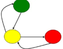
side of the signal, while in the case of autonomous, traffic is managed by observing the traffic on each side of the signal and set time accordingly. There are three different direction of the vehicles at the traffic signal which are left, right and straight [1]. The lights at signal changes as: green to yellow, red to yellow, yellow to green or red as shown in Figure 1. However, green light never changes to red light directly and vice versa.
The mechanism that is used for planning and controls traffic signals for vehicles on roads is known as the traffic management system. Traffic Volume 12, Issue 4, December 2018, pages 216–225
https://doi.org/10.12913/22998624/100387
Dynamic Traffic Control and Management System
for Smart Cities
Abdul Mateen
1*, Sabeen Sher
1, Amjad Rehman
2, Zahid Hanif
1,
Tooba Akhtar
1, Mahmood Ashraf
11 Department of Computer Science, Federal Urdu University of Arts, Science & Technology, Islamabad, Pakistan 2 College of Computer and Information Systems, Al Yamamah University, Riyadh,11512, Saudi Arabia
* Corresponding author’s e-mail: [email protected]
ABSTRACT
The computational capabilities of computers enable a human being to control the vehicles and their traffic. Au
-tomatic traffic control system not only reduces the effort of human but also provides secure and accurate results. Here, the architecture of Agent-Based Autonomous Controller (ABAC) that manages vehicles at traffic signals intelligently was proposed. The proposed solution is followed by a vehicle counting by infrared (IR) sensor; providing solution for independent and mutual dependent signals for smooth traffic flow; emergency vehicles alert and priority over public vehicles through Radio Frequency Identification (RFID). Finally, the proposed research was tested through simulation that reveals the performance over the previous traffic control and man
-agement architectures.
Keywords: traffic flow, management, mutual dependent, infrared
Research Journal
Accepted: 2018.11.05Available online: 2018.12.18
management is used to control traffic on roads in an effective way. For example, management of ve -hicles at extra lanes during rush hours and entrance ramp control. The Advanced Traffic Management System (ATMS) is a primary subfield within the In -telligent Transportation System (ITS). The ATMS view is a top-down management perspective that integrates technology primarily to improve the flow of vehicle traffic and safety.
Well-planned arrangements of components such as traffic signals, detectors or sensors and controller play a vital role in any tolling solution. Traffic signal lights are placed beside or above road to guide, warn, and regulate the flow of traf -fic, which includes motor vehicles, motorcycles, bicycles and pedestrians. An automated Traffic controller system is used to control and coordi -nate with the traffic lights in order to manage the vehicles at signals. A sensor is used to check the volume of traffic on signal and detection of some specialized vehicles such as ambulance, rescue etc. Nowadays, multiple sensors are used to detect vehicles, e.g. IR sensors, piezoelectric sensors, magnetic sensor and video vehicle detection etc.
IBM introduced the concept of autonomic computing in 2001 [2-6]. A number of systems have used the agent-oriented and autonomic com -puting approach since then. In agent-oriented systems, there are various agents which work to -gether in order to provide solution of the given problem [7]. In this piece of work, an agent-based architecture is proposed that is autonomous with respect to gathering data from the environment using sensors and making decisions that should handle the traffic loads smoothly in order to miti -gate congestions. The solution-based case study was also performed by taking the traffic data of Islamabad, capital of Pakistan. In this case study, the traffic signals were divided into two types, ac -cording to their relationship, i.e. independent and dependent signals. Two signals which are con -nected and close with each other are said to be mutual dependent traffic signals.
The rest of the paper is organized as follows: Section II discusses the previous research and studies that are dedicated to control and manage traffic. Section III presents the architecture of our proposed architecture to remove traffic conges -tion and handling of rescue vehicle. Sec-tion IV discusses the assign time algorithm of mutual dependent signal. Section V provides case study of mutual dependent signal. Section VI simulates the purposed architecture and its working. It re
-flects the effectiveness of the ABAC architecture and finally section VII provides the conclusion and future directions.
RELATED WORK
There are various studies which were carried out in past for traffic monitoring, control and man -agement. Some of these are discussed as under:
An agent-based traffic system was proposed where expertise of the agents is calculated by com -parison of nearby agents and weights are assigned to each [8-9]. The proposed method was tested on the traffic lights and achieved good results.
The traffic management architecture was pro -posed to handle the emergency vehicle [11-13] through Radio Frequency Identification (RFID). Specific vehicle is identified with coordinates by using RFID and Global Positioning System (GPS). Driver uses buzzer for emergency vehicle to open the signal.
Inductive loop that works on constant fre -quency [15] was introduced [15], in which wire ends are connected to the Monitor Unit. It uses a switch which is a few meters away from the traffic intersection. Whenever a vehicle is passed at that point an increment occurred in the vehicle count. When an emergency vehicle is reached, it communicates with Road Side Unit (RSU) and receives a tag for emergency vehicle. Due to the Radio Frequency Identification (RFID) on the emergency vehicle, emergency count is in -cremented and is sent to the Traffic Control Unit (TCU). If there are two or more emergency vehi -cles at any side, then the TCU turns on the green signal for that side. No manual effort is needed and priority is given to the emergency vehicle that saves time for the ambulances. The proposed system has the ability to work in all the condi -tions except the rough weather.
Predictive Road Traffic Management System (PRTMS) was introduced in [16]. PRTMS used a communication system to predict the future traf -fic congestion. Rerouting the vehicles is also in -cluded in PRTMS. Central Control Unit (CCU) is used to predict the future traffic congestion based on Linear Algorithm. A Road Side Unit (RSU) is used to exchange information from each inter -section. The RSU was connected with the CCU with Wide Area Network (WAN). Every vehicle should have an On Board Unit (OBU) that is re -sponsible of sending trip information including Point of Attraction (POA) through RSU. CCU predicts the traffic flow on every intersection and provides the trip route with minimum time. The RSU and OBU are connected wirelessly. When OBU is entered into the range of RSU, it is detected dynamically. Each RSU broad cast a packet in every second to each OBU. Each OBU sends a unicast response messages to RSU after 5 seconds. The RSU sends the traffic information to CCU through Ethernet link. Then, , the CCU predicts the traffic every minute and sends the route information to a corresponding RSU. The RSU delivers this message by broadcasting. At the same time the CCU changes the cycle time of the intersection. The proposed system depends upon the communication between CCU, RSU and OBU. The system is very complex and expensive; it is not possible to connect every vehicle with OBU country like in Pakistan.
Multi-agent system with two modes was introduced [17-18]; in the first mode, an agent learns from other agents without cooperation
but in the second mode, an agent learns from the other nearest agent through an algorithm. In the proposed system, emergency vehicles were given no priority and there is no explanation how these agents communicate with each other. Moreover, the system is much too slow and cannot work properly in poor weather conditions.
Two modules were proposed in [19] where system transmitter and receiver were used. When an emergency vehicle comes into the range of the radio waves, then the transmitter module of emergency vehicle sends the radio signal on the road side that is received by the Receiver. After processing the data, the green signal is turned on for the emergency vehicle. When an emergency vehicle crosses the intersection, the green light turns to red. The maximum range for the radio signal is 25 meters which is too short and may cause accidents.
The proposed system, as discussed in [20], obtained input from sensors and image processing techniques. The system proceeds on the number of vehicles and the average speed of the vehicles. Then green light works according to the traffic flow. However, the system is not efficient until all the intersection have communication and synchro -nization with each other. The other thing is that getting the input is major issue and crucial but in this system the mechanism of obtaining inputs is not clear, though the system seems to be very fast.
In the research that was presented in [21-22], the numbers of vehicles at each lane were counted and the Round Robin Scheduling Algorithm was applied. In an Intelligent Traffic Management System (ITMS), vehicles are assumed; otherwise, the number of vehicles is taken from the sensors or by applying image processing or some other technique. In the proposed system, there is no priority for emergency vehicles and ITMS frame -work may fail if any mishap occurs at the traffic control point.
that constitutes an optimized solution for traffic management by considering all relevant factors and constraints. Each vehicle was given time in such a manner that the average waiting time was reduced. The proposed traffic management archi -tecture was also tested through a simulation.
THE ABAC TRAFFIC MANAGEMENT
ARCHITECTURE
When there is huge traffic, autonomous agents are the better option to handle them. The Agent-Based Autonomous Controllers (ABAC) architecture for traffic management, where each component of the proposed architecture is repre -sented by an autonomous agent, was discussed. Here, these components were not discussed in de -tail, as they have already been discussed in our previous work.
Environmental Components
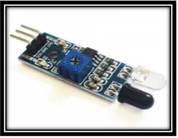
There are several ways to detect and count ve -hicles on road and traffic signal [10]. One method to detect a vehicle is by using IR Sensors. For each of the four roads that comes to junction have IR obstacle sensor modules that are installed at each lane. The IR sensor is also placed on the exit point of the road. These IR sensor modules only detect the obstacle which crosses the IR Beam. Each IR sensor works together with the Arduino board which is installed on each lane of the road. Each lane of the road is about 8 to 10 feet wide. There -fire, the range of IR Sensors is set to detect any vehicle that comes in the range of 8 to 10 feet only. Each road side has 4 lanes of 10 feet wide and each IR obstacle Sensor Modules Set consists of 4 IR sensors with the Arduino Uno board to detect and count vehicles that pass through these lanes.
Figure 2, shows the IR Obstacle module [24-25] which has 3 pins; 2 pins are used for power up the module that is 5V DC and 3rd pin is used for output. This module is connected to the Ar -duino Uno Board. The output pin of the module is attached to analog pin 2 of the Board. The IR module is installed at each lane of the road. The working principle of the IR Obstacle module [26] in which IR transmitter throw IR beam on object and it reflects back when any vehicle comes in its way. The beam reflected back is then sensed by the IR Receiver. The detection range can be changed by setting up the variable mounted on the IR Obstacle Module.
The value measured by the Analog pin of Arduino Uno is approximately 1000, when there is no vehicle. This value may decrease up to 200 when vehicle obstacles come into its range. When a vehicle is detected, a pulse (binary 1) is sent to the Main PIC controller to add the count by 1 to the vehicle count of that side. Note that for each lane of the road there the number of IR Sensors installed corresponds to the number of lanes. Therefore, if four vehicles come at a time on the road, an IR sensor is installed on each lane to detect only its own lane vehicle and send binary 1 to the main controller. Hence, vehicles are counted by the main controller and the same procedure is applied for the vehicles which exit from the exit point of the road junction. The IR sensor modules installed at the exit point of each lane send a pulse to the main controller when the vehicle obstacle is sensed, which deduces the counting variable value by 1 for each sensor of each lane of the road. This procedure is repeated for the signal to count the vehicles at each side of the signal. The road counting is then consid -ered by time allocation algorithm at the end of each timing cycle.
Nowadays, the number of vehicles on roads increases rapidly. These vehicles include cars, motorbikes, cabs, buses, trucks, as well as emer -gency vehicles like ambulances, fire brigade ve -hicles, police cars, VIP vehicles etc. Emergency vehicle need to be detected to give them priority over other public vehicles. Normal vehicles are detected through IR sensors, but it is not enough for detecting emergency vehicles.
emergency vehicle in a database. Each RFID tag contains important information of the emergency vehicle e.g., Vehicle Registration number, type (Ambulance, VIP, Fire brigade, police etc.,), En -gine number, chassis number etc.
The mounted RFID tags are detected by the RFID readers that are located on each lane of each road, approximately 500 meter away from the signal. Each emergency vehicle has their own RFID mounted Tag. When an emergency vehicle comes on the road at 500 meter away from the signal it is detected by RFID readers. As shown in Figure 3, a RFID reader reads the unique tag ID and relates the information from the database. If it is a valid Tag ID, then it gives signal to the DM to turn all signals to red, and green of the road from which an emergency ve -hicle is coming. Before turning all signals to red, the current state of signals is saved. When an emergency vehicle crosses the signal, DM re -store signal to its previous state. For each side of the road, there are two RFID Readers: one in -stalled on the entry and other on the exit point of junction.
Figure 4, shows the wiring diagram of RFID reader to arduino board [28].
MESSAGE FORWARDING FOR
EMERGENCY VEHICLE APPROACHES
TO NEXT SIGNAL
When an emergency vehicle is detected by the RFID Readers on the exit point of signal junction, a message is sent to the corresponding next signal about the incoming emergency vehicle. This mes -sage contains the information about the detected emergency vehicle, like the Vehicle Registration number, its type, and approximated time to reach the next signal junction.
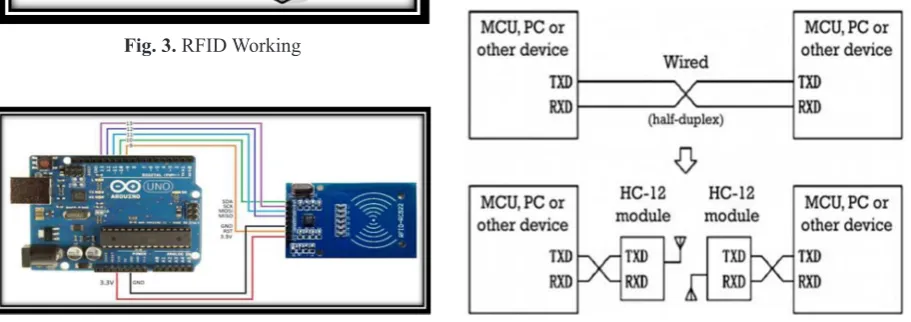
As shown in Figure 5, it uses 2 HC-12 mod -ules for wireless serial communication instead of physical wired commutation. When one mi -crocontroller sends data to other mi-crocontroller wirelessly it needs two HC-12 modules. Each one is connected to the one microcontroller. On the transmitting side, a microcontroller is connected to module in such a way that the transmitting pin of the controller is connected to the receiving pin of module and the receiving pin of the controller is connected to the transmitting pin of the mod -ule. The same connection scheme is repeated on the receiving side for second module and its mi -crocontroller [29].
Whenever a HC-12 module receives data on its receiving pin RXD, it automatically sends a signal wirelessly using radio waves. At the same time, the second HC-12 module receives data wirelessly and sends a signal to microcontroller from its transmitting pin TXD. This module al -lows half-duplex communication, meaning at a time, one module sends data and the other re -ceives it, and next time the other module sends signal, while the other module receives it. Both modules cannot send or receive data over the air at the same time [29].
Fig. 3. RFID Working
This communication of message to next sig -nal is done by using HC-12 (Wireless serial port communication) module. HC-12 uses multiple channels (up to 100 channels) within range of 433 to 437 MHz, each communication channel is about 400 KHz bandwidth. Maximum 100 mW of power is consumed in transmission at 20dBm. For longer distance communication, the serial baud rate should be reduced [29].
As multiple channels are available for commu -nication, different channels are used for communi -cation between four different directions of junction but similar channels for corresponding two signals (line of sight). This wireless communication takes place up to 2 kilometer distance using half duplex serial communication link. For reliable communi -cation, the baud rate must be 1200 for longer dis -tances. If we want to communicate over greater distances, we must set repeaters appropriately.
When a signal receives the input information from HC-12 module, the current information is analyzed and the time to approach the signal is calculated, then it is sent to a signal controller which then turns signal to green for an incoming emergency vehicle, before it approaches the sig -nal. After an emergency vehicle passes from the signal, the previous signal cycle is restored and the information on the exit of this emergency ve -hicle is sent to the next corresponding signal.
Knowledge Base
A database which stores the traffic intensity, threshold of each signal, traffic flow, distance of next connected signals at each side, emergency alarms and RFID tag information e.g. (ID, Ve -hicle Registration number, type).
Observer
It comprises an Analyzer, Decision Making (DM) and Learner agent.
Analyzer Agent: It takes the input from the
both IR sensor and RFID reader, makes decision about the dependent as well as mutual indepen -dent signal on the basis of distance to next signal and process accordingly. The traffic flow infor -mation is sent to DM agent. On the other hand, when a rescue sound is detected then DM agent is called for quick response.
Decision Making Agent: It receives two types
of inputs from the Analyzer agent, i.e. vehicle count from the IR sensor and emergency vehicle sound.
In the case of IR sensing, the assigned time is cal -culated by adding the exit time of first and next rows. The exit time for first row is calculated by using the formula 3600/10000 * Distance, where 3600/10000 represents the time to cover a meter when the vehicle’s average speed is 10 km/hour. This policy is adopted as vehicle initiates with 0 speed and finally reaches up to 20 km/hour when exits it the signal. The exit time for the next rows is calculated for 2 meters which is the distance of vehicle from its successor row. All four sides were assigned time by using this strategy. Finally, the signal is opened that has minimum time. Signal cycle time is updated on regular basis. when there is mutual dependent signal, first sum up the num -ber of vehicles of the dependent signal, 70% from straight signal. After summation, the assigned time is calculated by adopting the same startegy as mentioned for independent signal. However, when a sound is received from rescue vehicle, DM agent stores the current sequence into the knowl -edge base, restoring the signal sequence after 10 sec. The information about an emergency vehicle is passed to next signal for making arrangement of rescue vehicle passeged without any wait.
Learner Agent: It takes data from the reposi
-tory, with traffic flow patterns and updates the knowledge base if necessary that is further used by the Analyzer and DM agent in future.
MUTUAL DEPEDENT SIGNAL ASSIGN
TIME ALGORITHM
Mutual Signal Assign Time Algorithm (Fig -ure 6) is used to calculate the assigned time of all four sides of both the signals S1 and S2 as shown in (Figure 7) for handling huge traffic in an effec -tive way. This algorithm is invoked on the regular basis in order to update assign time of all sides of the signal and keep it updated according to the traffic flow. Mutual dependent sides of the signal update their assigned time according to the ve -hicle of the signal on which they are dependent.
CASE STUDY
Traffic is the common problem in large mod -ern cities as well as in third world countries. Developed countries have already paid keen at -tention to the traffic congestion problem and are solving it by adopting intelligent strategies. Traf -fic signals are divided into two types of signals i.e. independent and mutual dependent signals. The solution of mutual dependent signal was dis -cussed in this section, whereas the independent signals have already been discussed in our previ -ous paper [30].
Two signals which are connected and close to each other are said to be mutual dependent traffic signals. In the case of mutual dependent traffic signals, the traffic flow of one signal af -fects the traffic flow of the other signal and vice versa. There are 7 roads and each road has two sub-roads i.e. incoming and outgoing, as shown in Figure 7. The assigned time of the signal ‘C’ depends on the vehicles that are waiting on Signal ‘C’ and outgoing traffic of signal ‘G’. The case for signal ‘E’ is similar; the assigned time depends on the vehicles waiting on ‘A’.
Let us consider a mutual dependent traffic signal where the number of vehicles at signal A, B, C and D are 13, 20, 10 and 11 while at signal
E, F, G and H are 8, 21, 27 and 13 respectively. The above-mentioned mutual-dependent traf -fic signals can be represented through Figure 9, where each signal is denoted through a node and the incoming edge represents traffic or number of vehicles moving towards that node. The signals of Figure 7 are divided into two types, as shown in Figure 8, i.e. independent (A, B, D, F, G and H) – only depending on their own traffic, dependent (E, C) depends on its own and the vehicles wait -ing at signal (A, G) respectively.
The above-mentioned automata representa -tion can easily be understandable through an ad -jacency list. In graph theory, an ad-jacency list is a way to represent the nodes with their con -nectivity to other nodes. The first row of Table 1 represents the individual signal of the scenario above, while the second row shows the depen -dent signals.
As the signal A, B, D, F, G and H are inde -pendent signals; that is why they were calcu -lated according to the independent signal sce -nario. However, the assigned time and remain -ing assigned time (RTA) of the mutual depen -dent signals were calculated by using following formulae:
Assigned Time of C = No of vehicles (C + 0.7G) (1)
Assigned Time of E = No of vehicles (E + 0.7A) (2)
RTA of Signal B = (VB/VB+VD)·RT (3)
Fig. 6. Mutual Signal Assign Time Algorithm
Fig. 7. Mutual-Dependent Traffic Signal Scenario
In the equations above (1 and 2), 0.7 repre -sents 70% of the total vehicles that approached towards the respective signal. These ratios were taken very carefully and with various traffic flow scenarios. After experimenting, it was found that 70% of the traffic moved towards dependent sig -nal if it approached from the straight side. When the total time of both signals S1 and S2 are not same then RTA is added to the independent side of the signal having less time by using Eq (3), where calculation for only one signal is provid -ed. In the same way, this formula (eq. 3) was adopted according to the specific side of each independent signal. Table 2 represents the as -signed time and RTA to each signal by using the above-mentioned formulae.
SIMULATION AND RESULTS
Simulation provides the most effective way to handle and portray the real world problems. The traffic simulation can be categorized into deter -ministic (predictable) and stochastic [23, 27]. The deterministic simulation is the one which produc -es the same r-esult for specific input; on the other hand, the stochastic simulation may produce dif
-ferent outcome for same input. The other types of simulation are discrete or continuous. In discrete simulation, the system’s states are modeled and their states vary after a specific interval or event (discrete time and discrete event simulation), while in the continuous simulation state of the model is determined by calculating the equations which are based on real values.
Traffic Simulation Entitie and Environment Traffic simulation is used to simulate the flow of traffic in two types of vehicle traffic network, i.e. motorway and city traffic. However, here simulation was provided only for the city traffic. The main entities of the traffic include the cars, buses, roads and traffic signals. The traffic signals in this simulation were divided into independent and dependent traffic signal. There are four roads in the case of the independent traffic signal, while the dependent signal consists of two signals with six connecting roads. Vehicles and emergency ve -hicles are created on the roads randomly.
Independent Traffic Signal
The parameters used in calculation include the lanes, vehicles and priority in the case of emergency vehicles. The scenarios for indepen -dent traffic signals have already been discussed in [24] which showed that the ABAC architec -ture is more efficient than all other traffic control architectures.
Table 1. Signals with Associated Dependency
Independent
Signals A B D F G H
Dependent
Signals C E
Mutual-Dependent Traffic Signals
In this section, more complex form of the traf -fic signals i.e. dependent signals was discussed. Two signals which are connected and close to each other are called dependent traffic signals. In the case of the dependent traffic signals, the traffic flow of one signal affects the other signal and vice versa, as shown in Figure 9.
In the scenario above, signals are opened ac -cording to their number of vehicles waiting at some signal as well as their dependent signal’s traffic. The opening sequence of the dependent signal works according to vehicles.
Mutual Dependent Traffic Signals with Rescue Vehicle
Here, the case where the rescue vehicle ap -pears on the interconnected signals was consid -ered as shown in Figure 10. Priority of that road increases from where an emergency vehicle is coming and information about the emergency
vehicle is sent to the Decision Making agent of the next coming traffic signal. After obtaining this information, the next signal will modify its signal opening sequence in such a way so that the emer -gency vehicle passes away without any interfer -ence and delay.
In the above-mentioned scenario, an emer -gency vehicle is approaching to signal. Due to the emergency, the priority of this signal increases and signal is opened with 20 sec more than the actual allocated time. After the passage of the emergency vehicle, DM agent is responsible for sending information to the next signal. After re -ceiving this information, DM agent of next signal arranges the smooth passage of the emergency vehicle on first priority and after the emergency vehicle passage, the DM will resume signal to their previous sequence.
CONCLUSIONS
An autonomous agent-oriented traffic con -trol system which manages the traffic flow on signals was proposed to save time. It manages the traffic flow without any human intervention. Vehicles are counted by the IR sensor. The al -gorithm was purposed to allocate time for mu -tual dependent signals. The emergency vehicles were given priority over public vehicles by us -ing RFID tags. The research handles the traffic congestion problem intelligently and validated it through a simulation. The purposed system was demonstrated through simulation by taking dif -ferent traffic scenarios. In future, this architec -ture can be integrated with other systems such as traffic bulletin boards that show traffic conges -tion on next signal or road.
Acknowledgements
We are grateful to the Higher Education Com -mission (HEC) of Pakistan who are supporting this research work.
REFERENCES
1. Mueller E.A., Aspects of the history of traffic signals. IEEE T. on Vehicular Technology, 19(1), 1970, 6–17.
2. Horn P., Autonomic Computing: IBM’s Perspec
-tive on the State of Information Technology, IBM Journal, 2001.
Fig. 9. Dependent Traffic Signal Scenario
3. Kephart J.O. and Chess D.M., The Vision of Auto
-nomic Computing. Computer, 36(1), 2003, 41-50. 4. An Architectural blueprint for autonomic comput
-ing, IBM White paper, 3rd Edition, 2005.
5. Huebscher M.C.J. and Mccann A., A survey of Au
-tonomic Computing Degrees, Models, & Applica
-tions”, ACM Computing Surveys, 40(3), 2008. 6. Stuart R. and Peter N., Artificial Intelligence, A Mod
-ern Approach, 2nd Edition, 81-7758-367-0, 2008.
7. Alagar V.S. and Muthiayen D., A Rigorous Approach to Modeling Autonomous Traffic Control Systems. In: The 6th International Symposium on Autonomous
Decentralized Sys., Italy, 2003, 193-200.
8. Shamshirband S.S., Shirgahi H., Gholami M. and Kia B., Coordination between Traffic Signals Based on Cooperative, World App. Sc. J. Vol. 5 (5), 2008, 525-530.
9. Liu X. and Fang Z., An Agent-Based Intelligent Transport System. In: 11th Int. Conference on
Computer Supported Cooperative Work in Design, 2007, 304-315.
10. Casey M., MPEG-7 Sound Recognition Tools, Mitsubishi Electric Research Labs, Cambridge, MA, USA.
11. Albagul A., Hrairi M., Wahyudi, and Hidayathul
-lah M.F., Design & Development of Sensor Based Traffic Light System, American J. of App. Sc. 3 (3), 2006, 1745-1749.
12. Huang Y., Design of Traffic Light Control Systems Using Statecharts, The Computer Journal, 49(6), 2006.
13. Rajeshwari S., Hebbar S. and Golla V., Implement
-ing Intelligent Traffic Control System for Conges
-tion Control, Ambulance Clearance and Stolen Ve
-hicle Detection.
14. Bode M., Jha S.S. and Nair S.B. A mobile agent based autonomous partial green corridor discov
-ery and maintenance mechanism for emergency services amidst urban traffic. In: Proceedings of 1st
Int. Conference on IoT in Urban Space, 2014, pp. 13-18.
15. Bharadwaj R., Deepak J., Baranitharan M. and Vaidehi V.V. Efficient dynamic traffic control sys
-tem using wireless sensor networks. In: Recent Trends in Information Technology (ICRTIT), In
-ternational Conference on, IEEE, 2013, 668-673. 16. Nafi N.S., Khan R.H., Khan J.Y. and Gregory M.
A predictive road traffic management system based on vehicular ad-hoc network. In: Telecommunica
-tion Networks and Applica-tions Conference, Aus
-tralasian, IEEE, 2014, 135-140.
17. Grover S., Saxena V.S. and Vatwani T. Design of intelligent traffic control system using image seg
-mentation. Int. J. of Advances in Eng. & Tech., 7(5), 2014.
18. El-Tantawy S., Abdulhai B. and Abdelgawad H. Multiagent reinforcement learning for integrat
-ed network of adaptive traffic signal controllers (MARLIN-ATSC): Methodology and large-scale application on downtown Toronto. Intelligent Transportation Systems. IEEE Transactions on, 14(3), 2013, 1140-1150.
19. llmudin A., Hashim M.H.A., Ja’afar N.M.Z., Salleh A.S., Jaafar A., and Sam M.F.M. Traffic Light Control System using 434 MHz Radio Fre
-quency. Int. J. of Research in Advent Technology, 2(8), 2014, 26-31.
20. Latha J.R. and Suman U. Intelligent Traffic Light Controller. International Journal, 38, 2015. 21. Ramzanzad M. and Kanan H.R. A new method for
design and implementation of intelligent traffic control system based on fuzzy logic using FPGA. In IEEE Fuzzy Systems, 13th Iranian Conference,
2013, 1-4.
22. Alam M., Chowdhury M., and Purohit P. Develop
-ment of an Intelligent Traffic Manage-ment System Based on Modified Round-Robin Algorithm Emer
-gency, 7(12), 2014.
23. Champion A., Mandiau R., Kolski C., Heidet A. and Kemeny A. Traffic Generation with the SCAN
-eR II Simulator: Towards Mulit-Agent Architec
-ture. In: Proceedings of the first Driving Simula
-tion Conference, 1999, 311-324.
24. Elementz Engineers Private Limited, ,July 2018 http://www.elementzonline.com/ir-infrared-obsta
-cle-avoidance-sensor-module
25. Mreeco Electronics, July 2018, http://www.mree
- co.com/product/ir-infrared-obstacle-avoidance-sensor-module
26. Electronic Hub, August 2018, http://www.elec
-tronicshub.org/ir-sensor/
27. Traffic Simulation with Matlab, July 2018, https:// www.elprocus.com/rfid-basic-introduction-sim
-ple-application
28. Arduino, September 2018. https://create.arduino. cc/projecthub/gadget-programmers/online-atten
-dance-system-without-ethernet-c07682
29. Elecrow Technology, September 2018, https:// www.elecrow.com/download/HC-12.pdf
30. Mateen A., Khalid A., Khan L., Majeed S., and Akhtar T. Vigorous algorithms to control urban ve