1
INFLUENCE OF THE FLUID-WALL INTERACTION ON THE
MULTISCALE FLOW THROUGH A MICRO SLIT PORE CONSIDERING
THE ADSORBED LAYER-FLUID INTERFACIAL SLIPPAGE
Yongbin Zhang
*College of Mechanical Engineering, Changzhou University , Changzhou,213164, Jiangsu Province, China
ABSTRACT
A multiscale analysis is carried out for the pressure driven flow rate through a micro/nano slit pore when the adsorbed layer-fluid interfacial slippage is considered. The flow of the adsorbed layer on the channel wall is described by the flow factor approach model for nanoscale flow, and the flow of the continuum fluid intermediate between the two adsorbed layers is described by a continuum fluid model. The adsorbed layer-fluid interfacial slippage is considered, while the adsorbed layer-wall surface interfacial slippage is ignored. The weak, medium-level and strong fluid-wall interactions and the solid adsorbed layer assumption are respectively taken. It is shown that when the thickness of the adsorbed layer is far lower than the continuum fluid film thickness, the adsorbed layer can be treated as a solid layer in spite of the fluid-wall interaction, otherwise the fluid-wall interaction has a significant influence on the critical power loss on the channel for motivating the interfacial slippage and on the total volume flow rate through the channel before the occurrence of the interfacial slippage; However, when the adsorbed layer-fluid interfacial slippage occurs, the fluid-wall interaction has a negligible influence on the normalized total volume flow rate through the channel vs. power loss on the channel curve and when using this curve for calculating the dimensionless volume flow rate through the channel the adsorbed layer can be taken as a solid layer. In general, only when the fluid-wall interaction is strong, the adsorbed layer can be taken as a solid layer in simulating the channel flow.
Keywords: Adsorbed layer; Flow; Fluid; Interfacial slippage; Micro/nano channel; Multiscale
1. INTRODUCTION
When the channel inner size is big enough such as on the scales of 1mm or even 0.1mm, a continuum flow model is sufficient for describing the flow in the channel, and in this case the effect of the physical adsorbed layer on the channel wall can be neglected (Cho, 1982; Kawamura et al., 1986; Lemenand and Peerhossaini, 2002; Vallikivi et al., 2011). When the channel inner size is reduced to the scales of 1nm or 10nm, the fluid in the channel is whole adsorbed to the wall surface, the fluid is essentially continuum across the channel height, and a non-continuum flow model is required to describe this nanochannel flow by considering the fluid discontinuity and inhomogeneity effects across the channel height (Bitsanis et al., 1987; Jabbarzadeh et al., 1997; Somers and Davis, 1992; Zhang, 2006). There are the channel flows intervening between the macroscopic flow and the nanochannel flow, where the thickness of the adsorbed layer on the channel wall is comparable with the thickness of the continuum fluid film intermediate between the two adsorbed layers and the effect of the adsorbed layer is considerable on the channel flow. In this microchannel flow, a multiscale analysis is required for describing both the flows of the adsorbed layers and the flow of the intermediate continuum fluid. In the previous studies, molecular dynamics simulation (MDS) was used to model the flow of the adsorbed layer, and a conventional continuum flow theory was used to model the flow of the intermediate continuum fluid (Atkas and Aluru, 2002; Liu et al., 2007; Nie et al., 2004; Sun et al., 2010; Yang and Zheng, 2010; Yen et al., 2007). The shortcoming of these multiscale schemes is that they
*Email:[email protected]
should take long time to calculate an engineering problem because of the long channel size in the flow direction. Other multiscale approaches have also been proposed for saving the computational time, such as the MDS-LBM (lattice Boltzman method) scheme (Zhang, 2011) and the internal multiscale scheme (Borg et al., 2013), both of which use the MDS only in the smallest regions.
In the former study (Zhang, 2019), the author proposed a multiscale approach to the multiscale flow in a micro slit pore where the effect of the adsorbed layer on the channel wall should be considered. In this approach, the flow factor approach model for nanoscale flow describes the adsorbed layer flow, and a continuum flow model describes the flow of the intermediate continuum fluid. Three closed-form explicit flow equations have been given respectively for calculating the flow rates of the two adsorbed layers and the flow rate of the intermediate continuum fluid. Obviously, this approach has the advantage of giving fast solutions to a sort of engineering problems.
The present study is a successive work of the previous study (Zhang, 2019). It aims to explore the influence of the fluid-wall interaction on the multiscale flow in a micro channel. The adsorbed layer-fluid interfacial slippage is considered, while the adsorbed layer-wall surface interfacial slippage is ignored. The weak, medium and strong fluid-wall interactions are respectively taken. The results for them are compared with that based on the solid layer assumption. Important results and conclusions are obtained.
2. STUDIED CHANNEL FLOW
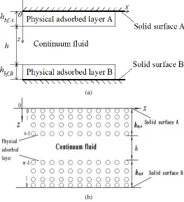
Figure 1(a) shows the studied pressure-driven flow in a micro slit pore
Frontiers in Heat and Mass Transfer
2 where the thicknesses (ℎ𝑏𝑓,𝐴 and ℎ𝑏𝑓,𝐵) of the physical adsorbed layers on the channel walls are comparable with the film thickness (ℎ) of the intermediate continuum fluid. In this channel, the flows of the adsorbed layer and the continuum fluid respectively occur on different size scales. Instead of by MDS, here the flow rate of the adsorbed layer is calculated from the flow factor approach model for nanochannel flow (Zhang, 2006) and the continuum fluid flow is calculated from the non-Newtonian flow theory with the interfacial slippage. The flow in Figure 1(a) can be equivalently treated as Figure 1(b) shows. The interfacial slippage on the adhering layer-fluid interface is assumed, but that on the adhering layer-wall surface interface is ignored, as in a normal channel flow the adhering layer-fluid interfacial slippage would more easily occur because of the adhering layer-fluid interface considerably weaker than the adhering layer-wall surface interface (Rozeanu and Snarsky, 1977). The adsorbed layers respectively on the coupled channel walls are taken as completely the same. The used coordinates are also shown in Figure 1(b).
(a)
(b)
Fig.1 The studied flow in a micro slit pore (Zhang, 2019).
3. ANALYSIS
The local density and viscosity across the adsorbed layer thickness is inhomogeneous because of the fluid-wall interaction. There are the local viscosity gradient and the varying separation between the neighboring molecules across the adsorbed layer thickness. Within the adsorbed layer, the local viscosity is defined as the ratio of the local shear stress to the local shear strain rate. The effective viscosity of the adsorbed layer is defined as the ratio of the shear stress on the wall surface to the velocity gradient across the adsorbed layer thickness when the adsorbed layer is in the Couette flow.
The interfacial slippage on the adsorbed layer-fluid interface is the result of the shear stress on this interface exceeding the shear strength of this interface. Because of the limited shear strength of the adsorbed layer-fluid interface, which is normally relatively weak, in the present pressure-driven flow, the shear stress on the adsorbed layer-fluid interface will be large so that its magnitude exceeds the shear strength of the adsorbed layer-fluid interface when the pressure gradient along the
channel is large enough. If this exceeding occurs, there is the relative motion of the adsorbed layer with respect to the continuum fluid on the adsorbed layer-fluid interface i.e. the interfacial slippage occurs on the adsorbed layer-fluid interface. Within the continuum fluid, the rheological model is still assumed as Newtonian.
For the case of isothermal laminar flow with ideally smooth channel walls, detailed multiscale analysis for the flow in Figure 1(b) has been shown by Zhang (2019); Because of the length and complexity, here only the derived results are listed. In Figure 1(b), the pressure gradient is assumed as negative so that the flow direction is from the left-hand side to the right-hand side.
3.1 When the adsorbed layer is treated as a flowing layer
For this case, the present multiscale scheme gives the dimensionless critical power loss per unit channel width on the channel for motivating the interfacial slippage as follows (Zhang, 2019):
𝐾cr= 2𝜆𝑏𝑓{
𝜀 (1+∆𝑥
𝐷)𝐶𝑦
+ 2𝜀𝜆𝑏𝑓
(1+∆𝑥
𝐷)𝐶𝑦
(1 − 𝑞0−𝑞0𝑛
𝑞0𝑛−1−𝑞0𝑛
∆𝑛−2
ℎ𝑏𝑓) −
𝜆𝑏𝑓𝐹1
3𝐶𝑦 +
1 6𝜆𝑏𝑓2
+ 1
𝐶𝑦𝜆𝑏𝑓{
1 1+∆𝑥
𝐷
− 2𝜆𝑏𝑓[
𝐹2
6− (1 −
𝑞0−𝑞0𝑛
𝑞0𝑛−1−𝑞0𝑛
∆𝑛−2 ℎ𝑏𝑓) 1 1+∆𝑥 𝐷 ]}} (1)
When the slippage occurs on both of the adsorbed layer-fluid interfaces, the dimensionless volume flow rate per unit channel width through the channel is calculated from the following equation (Zhang, 2019):
𝑄𝑣=𝐾12𝜆−𝐾𝑐𝑟
𝑏𝑓 + 1 𝐶𝑦[ 𝜀 1+∆𝑥 𝐷
+2𝜀𝜆𝑏𝑓
1+∆𝑥
𝐷
(1 − 𝑞0−𝑞0𝑛
𝑞0𝑛−1−𝑞0𝑛
∆𝑛−2
ℎ𝑏𝑓) −
𝐹1𝜆𝑏𝑓
3 ] + 1
6𝜆𝑏𝑓2
+ 1
𝐶𝑦𝜆𝑏𝑓{
1 1+∆𝑥
𝐷
− 2𝜆𝑏𝑓[𝐹62− (1 − 𝑞0−𝑞0
𝑛
𝑞0𝑛−1−𝑞0𝑛
∆𝑛−2 ℎ𝑏𝑓) 1 1+∆𝑥 𝐷 ]}
for 𝐾1≥ 𝐾𝑐𝑟 (2)
When no slippage occurs on the adsorbed layer-fluid interface, the dimensionless volume flow rate through the channel is calculated from the following equation (Zhang, 2019):
𝑄𝑣= 𝐾1
1/2
{ 𝜀
𝐶𝑦(1+∆𝑥𝐷)
(1 + 1
2𝜆𝑏𝑓−
𝑞0−𝑞0𝑛
𝑞0𝑛−1−𝑞0𝑛
∆𝑛−2
ℎ𝑏𝑓) −
𝐹1
6𝐶𝑦+
1
12𝜆𝑏𝑓3
−𝐶1
𝑦𝜆𝑏𝑓3 [
𝐹2𝜆𝑏𝑓2
6 − 𝜆𝑏𝑓
1+∆𝑥
𝐷
(12+ 𝜆𝑏𝑓− 𝑞0−𝑞0
𝑛
𝑞0𝑛−1−𝑞 0𝑛
∆𝑛−2
ℎ )]} 1/2
for 𝐾1< 𝐾𝑐𝑟 (3)
3.2 When the adsorbed layer is treated as a solid layer
For this case, only a continuum fluid flow occurs in the channel, and the results are derived as follows.
3.2.1 For the case of the interfacial slippage
When the interfacial slippage occurs on both of the adsorbed layer-fluid interfaces, the volume flow rate per unit channel width through the channel is: 𝑞𝑣,𝑠= 𝑢̅ℎ − ℎ 3 12𝜂 𝜕𝑝 𝜕𝑥= 𝑢̅ℎ +
ℎ2𝜏 𝑠,𝑏−𝑓
6𝜂
(4)
Where on the right-hand side, the first term is the Couette flow and the second term is the Poiseuille flow (𝑢̅ is the interfacial slipping velocity).
The power loss per unit channel width on the channel is: 𝑃𝑂𝑊𝑠=
∆𝑝𝑞𝑣,𝑠, where ∆𝑝 is the pressure drop on the channel. Substituting Eq. (4) into this equation and re-arranging gives that:
𝑃𝑂𝑊𝑠= 2𝜏𝑠,𝑏−𝑓Δ𝑙𝑢̅ + 𝑃𝑂𝑊𝑠,𝑐𝑟 (5)
Where 𝑃𝑂𝑊𝑠,𝑐𝑟 is the critical power loss per unit channel width on the channel for motivating the interfacial slippage and it is expressed as:
unit channel width on the channel for motivating the interfacial slippage is:
𝐾𝑠,𝑐𝑟=3𝜆1
𝑏𝑓 (6)
Substituting Eqs.(5) and (6) into Eq.(4) and re-arranging gives the dimensionless volume flow rate per unit channel width through the channel as follows:
𝑄𝑣,𝑠=
𝐾𝑠,1−𝐾𝑠,𝑐𝑟
2𝜆𝑏𝑓 +
1 6𝜆𝑏𝑓2
, for 𝐾𝑠,1> 𝐾𝑠,𝑐𝑟 (7)
3.2.2For the case of no interfacial slippage
When no interfacial slippage occurs anywhere, the volume flow rate per unit channel width through the channel is:
𝑞𝑣,𝑠=
ℎ3∆𝑝
12𝜂∆𝑙 (8)
The power loss per unit channel width on the channel is:
𝑃𝑂𝑊𝑠= ∆𝑝𝑞𝑣,𝑠=
12∆𝑙𝜂𝑞𝑣,𝑠2
ℎ3 (9)
Normalizing Eq.(9) gives that:
𝑄𝑣,𝑠=
1 𝜆𝑏𝑓√
𝐾𝑠,1
12𝜆𝑏𝑓 , for 𝐾𝑠,1≤ 𝐾𝑠,𝑐𝑟 (10)
4. CALCULATION
In the present calculation, ∆x/D = ∆𝑛−2/D = 0.15 and 𝜂𝑙𝑖𝑛𝑒,𝑖/
𝜂𝑙𝑖𝑛𝑒,𝑖+1= 𝑞0𝑚, where 𝑚 is a positive constant (Zhang, 2006). It was formulated that (Zhang, 2014):
C𝑦(𝐻𝑏𝑓) =
𝜂𝑏𝑓𝑒𝑓𝑓(𝐻𝑏𝑓)
𝜂 = 𝑎0+ 𝑎1
𝐻𝑏𝑓+
𝑎2
𝐻𝑏𝑓2 (11)
where 𝐻𝑏𝑓= ℎ𝑏𝑓/ℎ𝑐𝑟,𝑏𝑓, ℎ𝑐𝑟,𝑏𝑓 is a critical thickness, and 𝑎0, 𝑎1 and 𝑎2 are respectively constant and their values are shown in Table 1.
Table 1 Fluid viscosity data for different fluid-wall interactions (Zhang, 2014)
Parameter
Interaction a0 a`1 a2
Strong 1.8335 -1.4252 0.5917
Medium 1.0822 -0.1758 0.0936
Weak 0.9507 0.0492 1.6447E-4
The weak, medium and strong fluid-wall interactions considered respectively have the following characteristic parameter values: Weak interaction: m=0.5, n=3, 𝑞0= 1.03, ℎ𝑐𝑟,𝑏𝑓= 7𝑛𝑚 Medium interaction: m=1.0, n=5, 𝑞0= 1.1, ℎ𝑐𝑟,𝑏𝑓= 20𝑛𝑚 Strong interaction: m=1.5, n=8, 𝑞0= 1.2, ℎ𝑐𝑟,𝑏𝑓= 40𝑛𝑚
5. RESULTS
5.1 Dimensionless critical power loss on the channel for motivating the interfacial slippage
Figure 2 shows the dimensionless critical power loss per unit channel width on the channel for motivating the interfacial slippage when the adsorbed layer is respectively taken as a solid layer and a flowing layer. A notable point in this figure is that when the fluid-wall interaction is strong, for a given 𝜆𝑏𝑓 the values of 𝐾𝑐𝑟 and 𝐾𝑠,𝑐𝑟 are very close.
This again suggests that for a strong fluid-wall interaction, the adsorbed layer can be taken as a solid layer. However, for both the weak and medium fluid-wall interactions, if 𝜆𝑏𝑓 is so large as over 0.06 (i.e. the continuum fluid film thickness is not far larger than the adsorbed layer thickness), it is shown that the adsorbed layer can not be treated as a solid layer but should be taken as a flowing layer, and the solid layer assumption would give an underestimated calculation of the critical power loss on the channel for motivating the interfacial slippage especially for a weak fluid-wall interaction and a high 𝜆𝑏𝑓 value. It indicates that when the film thickness h of the intermediate continuum fluid is on the same scale with the thickness ℎ𝑏𝑓 of the adsorbed layer, for both the weak and medium fluid-wall interactions, the flowing property of the adsorbed layer should be considered.
Fig.2 Values of the dimensionless critical power loss per unit channel width on the channel for motivating the interfacial slippage respectively based on the solid layer and flowing layer assumptions.
5.2 Dimensionless volume flow rate through the channel
Figures 3(a)-(c) show the dependences of the dimensionless volume flow rate (𝑄𝑣 or 𝑄𝑣,𝑠) per unit channel width through the channel on the dimensionless power loss (𝐾1 or 𝐾𝑠,1) on the channel respectively for different 𝜆𝑏𝑓 and different fluid-wall interactions when the adsorbed layer is treated as a solid layer or a flowing layer. On each curve in these figures, there is a critical turning point which shows the beginning of the adsorbed layer-fluid interfacial slippage. After this point, for a given fluid-wall interaction, the dimensionless volume flow rate 𝑄𝑣 through the channel is rapidly increased with the increase of the power loss on the channel due to the interfacial slippage; Before this point, for a given fluid-wall interaction, because of the no slippage occurrence, the slope of the variation of 𝑄𝑣 with 𝐾1 is mostly significantly smaller than that in the case of the interfacial slippage. The benefit of the interfacial slippage in improving the volume and mass transportation through the channel is evident. The 𝑄𝑣 vs. 𝐾1 curve for the strong fluid-wall interaction is nearly completely overlaid with the 𝑄𝑣,𝑠 vs. 𝐾𝑠,1 curve based on the solid layer assumption. It further suggests that when the fluid-wall interaction is strong, the adsorbed layer can be treated as a solid layer and it has a very poor flowing ability. It is also noted that when the interfacial slippage occurs, the curves in Figs.3(a)-(c) for all the fluid-wall interaction types and for the solid layer assumption are nearly completely overlaid. This means that for any given fluid-wall interaction, when the interfacial slippage occurs, there is a very weak flowing behavior within the adsorbed layer and the adsorbed layer can be treated as a solid layer. However, when no interfacial slippage occurs, this treatment can not be done except for the case of the strong fluid-wall interaction; Otherwise, the volume flow rate through the channel will be considerably underestimated just because of being based on the solid
0 5 10 15 20 25
0.0 0.1 0.2 0.3 0.4 0.5
K
cr
,
K
s,cr
Solid layer
Strong interaction
Medium interaction
Weak interaction
bf
layer assumption. This is particularly severe for a weak fluid-wall interaction. According to the dimensional forms of Eqs.(1)-(3), for a given operating condition, overall a weak fluid-wall interaction is very helpful for the fluid transportation through the channel whenever the interfacial slippage occurs or is absent. This has also been verified by experiments (Joseph et al., 2006; Vinogradova et al., 2009).
(a) 𝜆𝑏𝑓= 0.05
(b) 𝜆𝑏𝑓= 0.1
(c) 𝜆𝑏𝑓= 0.2
Fig.3 Dependences of the dimensionless volume flow rate (𝑄𝑣 or
𝑄𝑣,𝑠) per unit channel width through the channel on the dimensionless power loss (𝐾1 or 𝐾𝑠,1)on the channel for different cases.
6. CONCLUSIONS
An analysis is presented for the pressure-driven volume flow rate through a micro slit pore based on the solid layer assumption when the adsorbed layer-fluid interfacial slippage occurs or not. In this microchannel flow, the effect of the adsorbed layer on the channel wall may be considerable due to the adsorbed layer thickness on the same scale with the channel height. The calculation results are compared with the multiscale calculation results for the same channel fow when the fluid-wall interaction is respectively weak, medium-level and strong and the adsorbed layer is treated as a flowing layer. It is shown that when the interfacial slippage occurs, for any given fluid-wall interaction, the adsorbed layer can be treated as a solid layer and it has a very poor flowing ability. This obviously substantially simplifies the analysis for the volume and mass transfer through the present particular micro channel, as a multiscale scheme for such a case is not required. However, when no interfacial slippage occurs, for both the weak and medium fluid-wall interactions, the adsorbed layer can not be treated as a solid layer, the multiscale analysis incorporating the adsorbed layer flow is required for the volume and mass transfer through the present channel, and it gives a considerably higher flow rate through the channel than that based on the solid layer assumption especially for a weak fluid-wall interaction. However, when the fluid-wall interaction is strong, even in the case of no interfacial slippage, the adsorbed layer can be taken as a solid layer and a multiscale analysis is not required for the flow in the channel just by neglecting the adsorbed layer flowing property.
NOMENCLATURE
𝑎0, 𝑎1, 𝑎2=constant, Eq.(11)
𝐶𝑦= 𝜂𝑏𝑓
𝑒𝑓𝑓
/𝜂
𝐷 = fluid molecule diameter
𝐹1= 𝜂𝑏𝑓
𝑒𝑓𝑓(12𝐷2𝜓 + 6𝐷𝜙)/ℎ
𝑏𝑓 3
𝐹2= 6𝜂𝑏𝑓
𝑒𝑓𝑓
𝐷(𝑛 − 1)(𝑙∆𝑙−1/𝜂𝑙𝑖𝑛𝑒,𝑙−1)𝑎𝑣𝑟,𝑛−1/ℎ𝑏𝑓2
ℎ = thickness of the intermediate continuum fluid
ℎ𝑐𝑟,𝑏𝑓= critical film thickness
ℎ𝑏𝑓,𝐴, ℎ𝑏𝑓,𝐵= thicknesses of the physical adsorbed layers on the coupled channel walls respectively
ℎ𝑏𝑓 = thickness of either of the adsorbed layers on the channel walls,
ℎ𝑏𝑓,𝐴 or ℎ𝑏𝑓,𝐵
𝐻𝑏𝑓= ℎ𝑏𝑓/ℎ𝑐𝑟,𝑏𝑓
𝑖, 𝑗 = order numbers of the fluid molecule across the adsorbed layer thickness respectively, Fig.1(b)
𝐾1= dimensionless power loss per unit channel width on the channel (used in the flowing adsorbed layer model), 𝑃𝑂𝑊𝜂/(𝜏𝑠,𝑏−𝑓2 ℎ𝑏𝑓Δ𝑙)
𝐾𝑠,1= dimensionless power loss per unit channel width on the channel (used in the solid layer model), 𝑃𝑂𝑊𝑠𝜂/(𝜏𝑠,𝑏−𝑓2 ℎ𝑏𝑓Δ𝑙)
𝐾𝑐𝑟= dimensionless critical power loss per unit channel width on the channel for motivating the interfacial slippage based on the flowing adsorbed layer model, 𝑃𝑂𝑊𝑐𝑟𝜂/(𝜏𝑠,𝑏−𝑓2 ℎ𝑏𝑓Δ𝑙)
𝐾𝑠,𝑐𝑟= dimensionless critical power loss per unit channel width on the channel for motivating the interfacial slippage based on the solid layer assumption
𝑚 = positive constant
𝑛 = equivalent number of the fluid molecules across the adsorbed layer thickness
𝑝 = fluid film pressure
𝑃𝑂𝑊𝑐𝑟= dimensional critical power loss per unit channel width on the channel for motivating the interfacial slippage based on the flowing adsorbed layer model
0 10 20 30 40 50 60 70 80 90 100
0 1 2 3 4 5 6 7 8 9 10
K1,Ks,1
Q
v
,
Q
v,s
Solid layer
Strong interaction
Medium interaction
Weak interaction
0 5 10 15 20 25 30 35 40 45 50
0 1 2 3 4 5 6 7 8 9 10
K1,Ks,1
Q
v
,
Q
v,s
Solid layer
Strong interaction
Medium interaction Weak interaction
0 5 10 15 20 25
0 1 2 3 4 5 6 7 8 9 10
K1,Ks,1
Q
v
,
Q
v,s
Solid layer
Strong interaction
Medium interaction
5
𝑃𝑂𝑊 =dimensional power loss per unit channel width on the channel (used in the flowing adsorbed layer model)
𝑃𝑂𝑊𝑠,𝑐𝑟=critical power loss per unit channel width on the channel for motivating the interfacial slippage based on the solid layer assumption
𝑞0= Δ𝑗+1/Δ𝑗(> 1)
𝑞𝑣= dimensional volume flow rate per unit channel width through the channel (used in the flowing adsorbed layer model)
𝑞𝑣,𝑠= dimensional volume flow rate per unit channel width through the channel based on the solid layer assumption
𝑄𝑣= dimensionless volume flow rate per unit channel width through the channel (used in the flowing adsorbed layer model), 𝑞𝑣𝜂/(𝜏𝑠,𝑏−𝑓ℎ𝑏𝑓2 )
𝑄𝑣,𝑠=dimensionless volume flow rate per unit channel width through the channel based on the solid layer assumption, 𝑞𝑣,𝑠𝜂/(𝜏𝑠,𝑏−𝑓ℎ𝑏𝑓2 )
𝑢̅=adsorbed layer-fluid interfacial slipping velocity based on the solid layer assumption
𝑥, 𝑧 = coordinates
𝜆𝑏𝑓= ℎ𝑏𝑓/ℎ
𝜂 = fluid bulk viscosity
𝜏𝑠,𝑏−𝑓=shear strength of the adsorbed layer-fluid interface
Δ𝑙 =channel dimension in the flow direction
Δ𝑝 =pressure drop on the channel
Δ𝑥 =separation between the neighboring fluid molecules in the flow direction
Δ𝑗−1, 𝜂𝑙𝑖𝑛𝑒,𝑗−1= separation and local viscosity between the 𝑗𝑡ℎand
(𝑗 − 1)𝑡ℎ fluid molecules across the adsorbed layer thickness
respectively
𝜂𝑏𝑓𝑒𝑓𝑓= effective viscosity of the adsorbed layer, 𝐷ℎ𝑏𝑓/ [(𝑛 − 1)(𝐷 +
Δ𝑥)(Δ𝑙/𝜂𝑙𝑖𝑛𝑒,𝑙)𝑎𝑣𝑟,𝑛−1]
ε = (2𝐷𝐼 + 𝐼𝐼)/ [ℎ𝑏𝑓(𝑛 − 1)(Δ𝑙/𝜂𝑙𝑖𝑛𝑒,𝑙)𝑎𝑣𝑟,𝑛−1]
𝑖(Δ𝑙/𝜂𝑙𝑖𝑛𝑒,𝑙)𝑎𝑣𝑟,𝑖= ∑ Δ𝑗−1/𝜂𝑙𝑖𝑛𝑒,𝑗−1 𝑖
𝑗=1
𝑖(𝑙Δ𝑙−1/𝜂𝑙𝑖𝑛𝑒,𝑙−1)𝑎𝑣𝑟,𝑖= ∑ 𝑗Δ𝑗−1/𝜂𝑙𝑖𝑛𝑒,𝑗−1 𝑖
𝑗=1
11
, ,
)
/
(
n
i
i avr l line l
i
I
𝐼 = ∑ 𝑖(Δ𝑙/𝜂𝑙𝑖𝑛𝑒,𝑙)𝑎𝑣𝑟,𝑖
𝑛−1
𝑖=1
𝐼𝐼 = ∑ [𝑖(Δ𝑙/𝜂𝑙𝑖𝑛𝑒,𝑙)𝑎𝑣𝑟,𝑖+ (𝑖 + 1)(Δ𝑙/𝜂𝑙𝑖𝑛𝑒,𝑙)𝑎𝑣𝑟,𝑖+1]
𝑛−2
𝑖=0
Δ𝑖
𝜓 = ∑ 𝑖(𝑙Δ𝑙−1/𝜂𝑙𝑖𝑛𝑒,𝑙−1)𝑎𝑣𝑟,𝑖
𝑛−1
𝑖=1
𝜙 = ∑ [𝑖(𝑙Δ𝑙−1/𝜂𝑙𝑖𝑛𝑒,𝑙−1)𝑎𝑣𝑟,𝑖+ (𝑖 + 1)(Δ𝑙/𝜂𝑙𝑖𝑛𝑒,𝑙)𝑎𝑣𝑟,𝑖+1]
𝑛−2
𝑖=0
Δ𝑖
REFERENCES
Atkas, O., Aluru, N. R., 2002, “A combined continuum/DSMC technique for multiscale analysis of microfluidic filters.” J. Comput. Phys, 178,342-372.
https://doi.org/10.1006/jcph.2002.7030
Bitsanis, I., Magda, J. J., Tirrell, M., Davis, H. T., 1987, “Molecular dynamics of flow in micropores.” J. Chem. Phys., 87, 1733-1750.
http://dx.doi.org/10.1063/1.453240
Borg, M. K., Lockerby, D. A., Reese J. M., 2013, “A multiscale method for micro/nano flows of high aspect ratio.” J. Comput. Phys., 233, 400-413.
http://dx.doi.org/10.1016/j.jcp.2012.09.009
Cho, Y. I., 1982, “Non-Newtonian fluids in circular pipe flow.” Adv. Heat Transf., 15, 59-141.
https://doi.org/10.1016/S0065-2717(08)70173-4
Jabbarzadeh, A., Atkinson, J. D., Tanner, R. I.,1997, “Rheological properties of thin liquid films by molecular dynamics simulations.” J.
Non-Newtonian Fluid Mech., 69, 169-193.
http://dx.doi.org/10.1016//S0377-0257(96)01520-0
Joseph, P., Cottin-Bizonne, C., Benoît, J. M., Ybert, C., Journet, C., Tabeling, P., Bocquet, L., 2006, “Slippage of water past superhydrophobic carbon nanotube forests in microchannels.” Phys. Rev. Lett., 97, 156104.
https:\\doi.org/10.1103/PhysRevLett.97.156104
Kawamura, T., Takami, H., Kuwahara, K., 1986, “Computation of high Reynolds number flow around a circular cylinder with surface roughness.” Fluid Dyn. Res., 1, 145-150.
https:\\doi.org/10.1016/0169-5983 (86)90014-6
Lemenand, T., Peerhossaini, H., 2002, “A thermal mode for prediction of the Nusselt number in a pipe with chaotic flow.” Appl. Therm. Eng.,
22, 1717-1730.
https://doi.org/10.1016/s1359-4311(02)00075-3
Liu, J., Chen, S., Nie, X., Robbins, M. O., 2007, “A continuum-atomistic simulation of heat transfer in micro- and nano- flows.” J. Comput. Phys.,
227, 279-291.
http://dx.doi.org/10.1016/j.jcp.2007.07.014
Nie, X. B., Chen, S., Robbins, M. O., 2004, “A continuum and molecular dynamics hybrid method for micro- and nano- fluid flow.” J. Fluid Mech.,
500, 55-64.
http://dx.doi.org/10.1017/s0022112003007225
Rozeanu, L., Snarsky, L., 1977, “The unusual behavior of a lubricant boundary layer.” Wear, 43, 117-126.
https://doi.org/10.1016/0043-1648(77)90047-3
Somers, S. A., Davis, H. T., 1992, “Microscopic dynamics of fluids confined between smooth and atomically structured solid surfaces.” J. Chem. Phys., 96, 5389-5407.
http://dx.doi.org/10.1063/1.462724
Sun, J., He, Y., Tao, W. Q., 2010, “Scale effect on flow and thermal boundaries in micro-/nano- channel flow using molecular dynamics-continuum hybrid simulation method.” Int. J. Num. Meth. Eng., 81, 207-228.
http://dx.doi.org/10.1002/nme.2683
Vallikivi, M., Hultmark, M., Bailey, S. C. C., Smits, A. J., 2011, “Turbulence measurements in pipe flow using a nanoscale thermal anemometry probe.” Exp. Fluids, 51, 1521-1527.
https:\\doi.org/10.1007/s00348-011-1165-4
Vinogradova, O. I., Koynov, K., Best, A., Feuillebois, F., 2009, “Direct measurements of hydrophobic slippage using double-focus fluorescence cross-correlation.” Phys. Rev. Lett., 102, 118302.
6 Yang, X., Zheng, Z. C., 2010, “Effects of channel scale on slip length of flow in micro/nano channels.” ASME J. Fluids Eng., 132, 061201. http://dx.doi.org/10.1115/1.4001619
Yen, T. H., Soong, C. Y., Tzeng, P. Y., 2007, “Hybrid molecular dynamics-continuum simulation for nano/mesoscale channel flows.”
Microfluid. Nanofluid., 3, 665-675.
http://dx.doi.org/10.1007/s10404-007-0154-7
Zhang, Y. B., 2006, “Flow factor of non-continuum fluids in one-dimensional contact.” Industr. Lubr. Trib., 58, 151-169.
http://dx.doi.org/10.1108/00368790610661999
Zhang, J., 2011, “Lattice Boltzman method for microfluidics: models and applications.” Microfluid. Nanofluid., 10, 1-28.
http://dx.doi.org/10.1007/s10404-010-0624-1
Zhang, Y. B., 2014, “Lubrication analysis for a line contact covering from boundary lubrication to hydrodynamic lubrication: Part I- Micro contact results.” J. Comput. Theor. Nanosci., 11, 62-70.
https:\\doi.org/10.1166/jctn.2014.3336