Available Online at www.ijpret.com 226
INTERNATIONAL JOURNAL OF PURE AND
APPLIED RESEARCH IN ENGINEERING AND
TECHNOLOGY
A PATH FOR HORIZING YOUR INNOVATIVE WORK
SECURE PACKET USING DYNAMIC PROBABILISTIC PACKET MARKING
ANIL V. TURUKMANEComputer Science & Engineering Department, Dr. Babasaheb Ambedkar University, Aurangabad, India Accepted Date: 05/03/2015; Published Date: 01/05/2015
\
Abstract: Most of the probability of packet marking (PPM) have existed many problems such as the loss of marking information, the difficulties to reconstruct attack path, low accuracy and so on. In this work, we present a new approach, called dynamic probabilistic packet marking (DPPM), to further improve the effectiveness of PPM. Instead of using a fixed marking probability, we propose to judge whether the packet has been marked or not then choose a proper marking probability. DPPM may solve most of the problems in PPM method. Formal analysis indicates that DPPM outperforms PPM in most aspects.
Keywords: Structured Network, Secure Data Sharing.
Corresponding Author: MR. ANIL V. TURUKMANE
Access Online On:
www.ijpret.com
How to Cite This Article:
Anil V. Turukmane, IJPRET, 2015; Volume 3 (9): 226-233
Available Online at www.ijpret.com 227 INTRODUCTION
The denial-of-service (DoS) attack has been a pressing problem in recent years. DoS defiance research has blossomed into one of the main streams in network security. Various techniques such as the pushback message, ICMP trace back, and the packet filtering techniques are the results from this active field of research. The probabilistic packet marking (PPM) algorithm by Savage et al. Has attracted the most attention in contributing the idea of IP trace back. The most interesting point of this IP trace back approach is that it allows routers to encode certain information on the attack packets based on a predetermined probability. Upon receiving a sufficient number of marked packets, the victim (or a data collection node) can construct the set of paths that the attack packets traversed and, hence, the victim can obtain the location(s) of the attacker(s).
The Probabilistic Packet Marking Algorithm The goal of the PPM algorithm is to obtain a constructed graph such that the constructed graph is the same as the attack graph, where an attack graph is the set of paths the attack packets traversed, and a constructed graph is a graph returned by the PPM algorithm. To fulfill this goal, Savage et al. suggested a method for encoding the information of the edges of the attack graph into the attack packets through the cooperation of the routers in the attack graph and the victim site. Specifically, the PPM algorithm is made up of two separated procedures: the packet marking procedure, which is executed on the router side, and the graph reconstruction procedure, which is executed on the victim side.
The packet marking procedure is designed to randomly encode edges’ information on the packets arriving at the routers. Then, by using the information, the victim executes the graph reconstruction procedure to construct the attack graph. We first briefly review the packet marking procedure so that readers can become familiar with how the router marks information on the packets.
R1
R2
R3
V
R1
R2
R3
X
V
X: Source V: Victim
R1,R2,R3: Routers
Router inscribes ( ) onto a packet With probability p
i
R Ri1,Ri
Attack path Reconstruction
Available Online at www.ijpret.com 228
Example – Probabilistic Packet Marking
A new probabilistic packet marking technology (called as P3M) based on path identification to defense serious distributed denial of service attacks and solves complex computation and other problem existed in traditional probabilistic packet marking (PPM) technologies. First contribution is constructing a new payload to carry router address and path identification. The second contribution is designing a new path identification scheme based on router addresses and hash algorithm. P3M is a practical technology to defense DDoS.
To overcome above shortcomings, we design a new probabilistic packet marking technology -- P3M in this article. Comparing with the traditional PPM technologies, our first contribution is a new payload (called as P3M payload below) carrying router address and path identification to avoid influencing the normal running of recombining packets and Qos mechanism. Our second contribution is a new path identification scheme based on router addresses and hash algorithm. The use of path identification makes our probabilistic packet
Marking technology P3M simple when victim computes DDoS attack paths. And path identification also could be used by other network security equipment’s.
1. P3M TECHNOLOGY
P3M payload
Definite a new payload in P3M and insert it between ip header and transport layer header to carry router address and path identification which is different with existing technologies.
R1
R2
R3
V
X
V
X
V
0
R
1
X
X
V
1
R
2
R
1
X
V
2
R
2
R
1
Distance from router Edge start Edge end
Available Online at www.ijpret.com 229 Figure 1. P3M payload format
2. PATH IDENTIFICATION
Idea is: every router passed by the packet will insert a globally unique identifier into the “Path Identification” domain, so the packets arriving at the receiver through different network paths must have different “Path Identification” domain values.
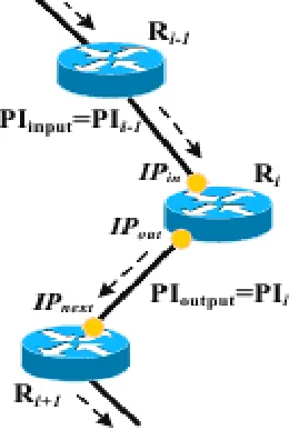
Figure 2. Path identification technology
In Figure, the dashed represents the path that packet P passed. IPin and IPout respectively is the ip address of Ri’s network interface that P goes into and out. For packet P, Ri’s next hop is IP next. Pretending the path identification computed by router Ri-1 is PIi-1, Ri will compute PIi according to formula (1).
Available Online at www.ijpret.com 230
3. PRINCIPLE OF P3M TECHNOLOGY
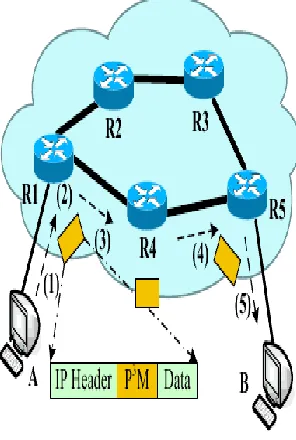
As shown in Figure 3, pretending routers R1, R4, R5 have deployed P3M technology and the network path between terminals A and B is Path AB= {R1, R4, R5}, so the work flow between A and B is:
Figure 3. P3M scheme
A sends a packet P whose source ip address is IPa and destination ip address is IPb.
After P arrives at router R1, firstly R1 will insert a P3M payload between P’s ip header and transport layer data, alter the “Protocol” domain value of ip header to 256 and insert its raw value to P3M payload’s “Procotol” domain. Secondly, R1 set P3M payloads “Hops” domain 1, and compute the “Path Identifier” value PI1 according to formula (1). Finally, R1 get p by computing according to formula (2) and alter the “Router Address” and “Locator” domain value by probability p. Notice that the “Locator” domain value is equal to “Hops” domain value.
P = 1 / h (2)
In formula (2), h is the currently “Hops” value. After above processing, R1 transmits packet
Available Online at www.ijpret.com 231
transmits packet P.R5 will perform the same operation as R4.P reaches the destination B. If B finds DDoS attack, after receiving a certain amount of packets, it can reconstruct the DDoS attack paths by its trapped P3M payloads.
The packet marking procedure aims at encoding every edge of the attack graph, and the routers encode the information in three marking fields of an attack packet: the start, the end, and the distance fields (wherein Savage ET alohas discussed the design of the marking fields). In the following, we describe how a packet stores the information about an edge in the attack graph, and the pseudo code of the procedure in is given in Fig. 1 for reference.
When a packet arrives at a router, the router determines how the packet can be processed based on a random number x (line number 1 in the pseudo code). If x is smaller than the predefined marking probability pm, the router chooses to start encoding an edge. The router sets the start field of the incoming packet to the router’s address and resets the distance field of that packet to zero. Then, the router forwards the packet to the next router.
When the packet arrives at the next router, the router again chooses if it should start encoding another edge.
For example, for this time, the router chooses not to start encoding a new edge. Then, the router will discover that the previous router has started marking an edge, because the distance field of the packet is zero. Eventually, the router sets the end field of the packet to the router’s address. Nevertheless, the router increments the distance field of the packet by one so as to indicate the end of the encoding.
Now, the start and the end fields together encode an edge of the attack graph. For this encoded edge to be received by the victim, successive routers should choose not to start encoding an edge, that is, the case x > pm in the pseudo code, because a packet can encode only one edge.
5 EXECUTION DIAGRAM OF THE DYNAMIC PROBABILISTIC PACKET MARKING ALGORITHM According to the previous section, it is observed that the TPN, the constructed graph, and the execution of the rectified graph reconstruction procedure are closely related. Such a relationship can be visualized by the construction of the execution diagram, The execution diagram presents the dynamics of the execution of the rectified graph reconstruction procedure.
Available Online at www.ijpret.com 232
an execution state.” Otherwise, we say that “the rectified graph reconstruction procedure is in the termination state.” 1) When the procedure is in the start state, labeled by “0,” it means that the procedure has started running, and there are no edges in the constructed graph. 2) When the procedure is in a connected state, it means that the constructed graph is connected. A connected state, labeled by Ci , means that the constructed graph is connected and contains i edges.
3) When the procedure is in a disconnected state, the constructed graph is disconnected. A disconnected state, labeled by Di , means that the constructed graph is disconnected and contains i edges. Note that both the connected and disconnected states, say, Ci and Di , respectively, refer to all the possible graphs that have i edges. Last, when the procedure is in the termination state, it means that the procedure has stopped.
There are two kinds of transitions in the execution diagram. When the procedure takes a growth transition, it means that a new edge is added to the constructed graph. When the procedure takes a termination transition, it means that the procedure is going to stop running. The transition structure is derived from the pseudocode of the rectified graph reconstruction procedure.
1) If a packet that encodes a new edge arrives before the number of received packets is larger than the TPN, then the procedure takes a growth transition and proceeds to either a connected state or a disconnected state, depending on the connectivity of the updated constructed graph.
2) If the number of received packets is larger than the TPN, then the procedure takes the termination transition and proceeds to the termination state.
3) If the procedure is in one of the disconnected states, then it is meaningless to return such a graph as the correct constructed graph, and there is no transition that connects the disconnected states to the termination state.
6. CONCLUSION
Available Online at www.ijpret.com 233
Path reconstruction is the fundamental goal of packet marking. Reduced false positives. High false positives are actively suppressed due to the above improvements. Effectiveness to handle large-scale DDoS attacks which is dominant in today’s Internet.
REFERENCES
1. Software Engineering – A Practitioners Approach, 7th Edition by Pressman UML User Guide,
By Grady Booch, James Rumbaugh and Ivar JacobsanF. Baker. Requirements for IP Version 4 Routers. RFC 1812, June 1995.
2. S. Savage, D. Wetherill, A. Karl in, and T. Anderson, “Network Support for IP Trace back,” IEEE/ACM Trans. Networking, vol. 9, pp.226-237, Jun. 2001.
3. D. Song and A. Perrig, “Advanced and Authenticated Marking Schemes for IP trace back,” IEEE INFOCOM 2001, Anchorage, AK.
4. A. Year, A. Perrig, and D. Song, “Fast Internet Trace back,” IEEEINFOCOM 2005, in press. 5. T. Peng, C. Leckie and R. Kotagiri, “Adjusted Probabilistic Packet Marking for IP trace back,” Proc. Of Networking, 2002, Pisa, Italy, May 2002.
6. J. Liu, Z. Lee, and Y. Chung, “Efficient dynamic probabilistic packet marking for IP trace back,” the 11th International Conf. Networks (ICON 2003), Sydney, Australia, Sep. 2003.
7. B. Rizvi and E. Fernandez-Gaucherand, “Analysis of adjusted Probabilistic Packet Marking,” IP Operations & Management (IPOM2003), Kansas City, MO, Oct. 2003..
8. M. Adler, “Tradeoffs in Probabilistic Packet Marking for IPTraceback,” Annual ACM Symp. Theory of Computing’02, Quebec, Canada, 2002.
9. H. Aljifri, M. Smets and A. Pons, “IP traceback using headercompression,” Computer & Security, vol. 22, pp.136-151, 2003.