Available Online at www.ijpret.com 1689
INTERNATIONAL JOURNAL OF PURE AND
APPLIED RESEARCH IN ENGINEERING AND
TECHNOLOGY
A PATH FOR HORIZING YOUR INNOVATIVE WORK
A MULTIPLE LEVEL EXAMPLAR BASED IMAGE INPAINTING WITH SINGLE IMAGE
SUPER RESOLUTION
BALU TANDALE, DIMPLE CHAUDHARI
Dept. of Electronics &Telecommunication Eng., YTIET, Karjat, Mumbai-410201 Accepted Date: 15/03/2016; Published Date: 01/05/2016
\
0
Abstract: This paper introduces a complete framework for examplar-based in painting. It
consists in performing first the in painting on a coarse version of the input image. A hierarchical super-resolution algorithm is then used to recover details on the missing areas. The advantage of this approach is that it is easier to inpaint low-resolution pictures than high-resolution ones. The gain is both in terms of computational complexity and visual quality. However, to be less sensitive to the parameter setting of the in-painting method, the low-resolution input picture is in-painted several times with different configurations. Results are efficiently combined with a loopy belief propagation and details are recovered by a single-image super-resolution algorithm. Experimental results in a context of image editing and texture synthesis demonstrate the effectiveness of the proposed method. Results are compared to five state-of-the-art in-painting methods.
Keywords: Examplar-based inpainting, single-image, super-resolution, loopy belief
propagation
Corresponding Author: MR. BALU TANDALE Access Online On:
www.ijpret.com
How to Cite This Article:
Balu Tandale, IJPRET, 2016; Volume 4(9): 1689-1703
Available Online at www.ijpret.com 1690 INTRODUCTION
Available Online at www.ijpret.com 1691
energy functional defined on a class of images which is then used as a regularization term together with interpolation techniques [11]. This prior information can also take the form of example images or of corresponding LR-HR (Low Resolution - High Resolution) pairs of patches learned from a set of un-related training images [12] or from the input low resolution image itself [13]. This latter family of approaches is known as based SR methods [12]. An examplar-based super- resolution method embedding K nearest neighbours found in an external patch database has also been described in [14]. Instead of constructing the LR-HR pairs of patches from a set of un-related training images, the authors in [13] extract these correspondences by searching for matches across different scales of a multi-resolution pyramid constructed from the input low-resolution image. The proposed method builds upon the super-resolution-based inpainting method proposed in [10] which is based on examplar-based inpainting(in particular Criminisi-like approach [4]) and single-image examplar-based super- resolution [13]. The main novelty of the proposed algorithm is the combination of multiple inpainted versions of the input picture. The rationale behind this approach is to cope with the sensitivity of examplar-based algorithms to parameters such as the patch size and the filling order. Different combinations have been tested and compared. Besides this major point, different adjustments regarding examplar-based inpainting and SR methods are described such as the use of the coherence measure to constrain the candidate search [15].In summary, the proposed method improves on the state- of-the-art examplar-based inpainting methods by proposing a new framework involving a combination of multiple inpainting versions of the input picture followed by a single-image examplar-based SR method. Notice that the SR method is used only when the inpainting method is applied on a low resolution of the input picture.The paper is organized as follows. In Section II, an overview of the proposed examplar-based inpainting algorithm is presented. In Section III, the details of the inpainting algo- rithm as well as the combination of the inpainted pictures are given. Section IV presents the super-resolution method. Experiments and comparisons with state-of-the-art algorithms are performed in Section V. Finally we conclude this work in Section VI.
2. Notat ions and al gorithm overvie w Notation
The following notations are used throughout this paper:
Available Online at www.ijpret.com 1692
x
px
𝐼: |£ϲ𝑅𝑋→𝐼(𝑋)𝑛→𝑅𝑚
Where n = 2 and in this case x = (x , y) represents
a vector indicating spatial coordinates of a pixel px.
£ is the generic definition domain of images. I is a color image composed of three components (m = 3). Here, we consider the ( R, G, B ) color space.
• Ii : £ → R represents the i th image channel of I.
• The definition domain is here composed of two parts:
£ = S ∪ T , S being the known part of I (source region) and T the target one or unknown parts of I.
Î(𝑐) is the inpainted picture obtained by using the 𝐶𝑡ℎ setting configuration.
Î(∗) is the final inpainted picture.
• We denote by 𝑝𝑥𝑘 the pixel located at x in the image I(k) .
ψ px is the patch centered on the pixel px.
L R and H R denote Low Resolution
and High Resolution respectively. ψ H R is a patch of high resolution.
D H R is a set of HR patches (a dictionary) which is used by the super-resolution algorithm.
B. Algorithm Overview
Image completion of large missing regions is a challenging task. As presented in the previous section, there are a number of solutions to tackle the inpainting problem. In this paper, we propose a new inpainting framework relying on both the combination of low-resolution inpainting pictures method and a single-image super-resolution algorithm. In the following sections, we briefly present the main ideas of this paper and the reasons why the proposed method is new and innovative.
Available Online at www.ijpret.com 1693
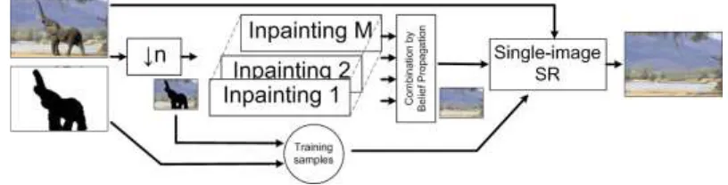
picture. Indeed a low-resolution picture is mainly represented by its dominant and important structures of the scene. We believe that performing the inpainting of such a low-resolution image is much easier than performing it on the full resolution. A low-resolution image is less contaminated by noise and is composed by the main scene structures. In other words, in this kind of picture, local orientation singularities which could affect the filling order computation are strongly reduced. Second, as the picture to inpaint is smaller than the original one, the computational time is significantly reduced compared to the one necessary to inpaint the full resolution image. To give more robustness, we inpaint the low-resolution picture with different settings (patch’s size, filling order, etc). By combining these results, a final low-resolution inpainted picture is obtained. Results will show that the robustness and the visual relevance of inpainting is improved. The second operation is run on the output of the first step. Its goal is to enhance the resolution and the subjective quality of the inpainted areas. Given a low-resolution input image, which is the result of the first inpainting step, we recover its high-resolution using a a single-image super resolution method. Single-image super-resolution approach. Fig. 1 illustrates the main concept underlying the proposed method namely: 1) a low-resolution image is first built from the original picture;
2) An inpainting algorithm is applied to fill in the holes of the low-resolution picture. Different settings are used and inpainted pictures are combined;
3) The quality of the inpainted regions is improved by using a single-image super-resolution method.
III. Multiple examplar-based inpainting
This section aims at presenting the proposed inpainting method and the combination of the different inpainted images.
A. Examplar-Based Inpainting:
The proposed examplar-based method follows the two clas- sical steps as described in [4]: the filling order computation and the texture synthesis. These are described in the next sections. 1) Patch Priority:
Available Online at www.ijpret.com 1694
exactly the one defined in [4]. Regarding the data term, a tensor-based [9] and a sparsity-based [16] data terms have been used. These terms are briefly described below.
The tensor-based priority term is based on a structure tensor also called Di Zenzo matrix [17]; this is given by:
J = ∑𝑚 ∇I𝛻𝐼𝑇.
𝑖=0 (1)
J is the sum of the scalar structure tensors ∇Ii∇I T
i of each image channel Ii (R,G,B). The tensor can be smoothed without cancellation effects: Jσ = J * Gσ where Gσ = 1/2πσ2 exp(−(x2+y2)/2σ2), with standard deviation σ. One of the main advantages of a structure tensor is that a structure coherence indicator can be deduced from its eigenvalues. Based on the discrepancy of the eigenvalues, the degree of anisotropy of a local region can be evaluated. The local vector geometry is computed from the structure tensor Jσ. Its eigen vectors v1, v2 (viƐRn) define an oriented orthogonal
basis and its eigenvalues λ1,2 define the amount of structure variation. The vector v1 is the orientation with the highest fluctuations (orthogonal to the image contours), whereas v2 gives the preferred local orientation. This eigenvector (having the smallest eigenvalue) indicates the isophote orientation. A data term D is then defined as [18:]
D(Px) = α + (1 − α) exp (− η
(λ1 − λ2)2) (3)
Where η is a positive value and α ∈ [0, 1] (η = 8 and α = 0.01). On flat regions (λ1 ≈ λ2), any direction is favoured for the propagation (isotropic filling order). When λ1 >> λ2 indicating the presence of a structure, the data term is important. The sparsity-based priority has been proposed recently by Xu et al. [16]. In a search window, a template matching is performed between the current patch ψpx and neighbouring patches ψpj that belong to the known part of the image. By using a non-local means approach [15], a similarity weight wpx,pj (i.e. proportional to the similarity between the two patches centered on px and pj) is computed for each pair of patches. The sparsity term is defined as:
D(Px) = ‖Wpx‖ ×√|Ns(px)| .
Available Online at www.ijpret.com 1695
where Ns and N represent the number of valid patches (having all its pixels known) and the total number of candidates in the search window. When _‖Wpx‖_2 is high, it means larger sparseness whereas a small value indicates that the current input patch is highly predictable by many candidates.
2) Texture Synthesis: The filling process starts with the patch having the highest priority. To fill in the unknown part of the current Patch ᴪukpx
.
, the most similar patch located in a local neighbourhood W centered on the current patch is sought. A similarity metric is used for this purpose. The chosen patch ᴪpx∗ maximizes the similarity between the known pixel values of the current patch to be ᴪuk
px .
filled in ψk px and co-located pixel values of patches belonging to W:
ᴪpx∗ = arg ᴪpjminɛW d(ᴪkpx, ᴪkpj) (5)
S.t coh(ᴪukpx .
) < λcoh
Where d(.) is the weighted Bhattacharya used in [10]. Coh(.)
Is the coherence measure initially proposed by Wexler et al. (15)
coh(ᴪpxuk) =pj ɛ S.
min(d
SSD(ᴪpx
uk, ᴪuk
pj)) (6)
Where dSSD is the sum of square differences. The coherence measure Coh simply indicates the degree of similarity between the synthesized patch ᴪpxuk and original patches. Therefore, the constraint in equation (5) prevents pasting in the unknown regions a texture that would be too different from original textures. If none of the candidates fulfil the constraint (5), the filling process is stopped and the priority of the current patch is decreased. The process restarts by seeking the patch having the highest priority. It is interesting to note that a recent study [19] uses a similar term to predict the quality of the inpainting. Compared to our previous work [10], there is another substantial difference: we only use the best match to fill in the hole whereas a linear combination of the K most similar patches is generally performed to compute the patch ᴪp∗x in [10], [15], [16], [20]. In these cases, the estimated patch is then given by:
Available Online at www.ijpret.com 1696
Where K is the number of candidates which is often adapted locally so that the similarity of chosen neighbours lies within a range (1+α) ×dmin, where dmin is the distance between the current patch and its closest neighbours. Different methods can be used to compute the weights. It could be based on either a non-negative matrix factorization (NMF) [21] or a non-local means filter [15], [22], to name a few. Combining several candidates increases the algorithm robustness However, it tends to introduce blur on fine textures as illustrated by Fig. 2. In our method, only the best candidate is chosen. Its unknown parts are pasted In to the missing areas. A Poisson fusion [23] is applied to hide the seams between known and unknown parts. An α-blending is also applied to combine known parts (ψk Px ← αψk px\ + (1 − α)ψk, px , with α = 0.75). It gives more robustness by locally regularizing the results. Although the proposed method is able to fill in holes in a visually pleasant fashion (as illustrated by Figs. 2 and 9), it still suffers from problems of one-pass greedy algorithms. Indeed for most of existing approaches, the setting such as the patch size and the filling order, to name the most important factors, may dramatically impact the quality of results. To overcome this issue, we combine inpainted pictures obtained when different settings are used. In this study, we consider M = 13, meaning that the low-resolution picture is inpainted 13 times. Parameters are given in Table I: the patch size is chosen between 5 × 5, 7 × 7, 9 × 9 and 11 × 11. The filling order is computed by either the sparsity-based or the tensor-based method. The input picture can also be rotated by 180 degrees. This allows changing the filling order
Available Online at www.ijpret.com 1697
1. Original 2. TM
3. NLM 4. NMF
Original Mask Inpainted Image
B. Combining Multiple Inpainted Images
The combination aims at producing a final inpainted picture from the M inpainted pictures. Before delving into this subject in details, Fig. 3 illustrates some inpainted results obtained.
Table1: Configurations used to fill in the unknown parts of the picture
Setting Parameters
1 Patch’s size 5 × 5
Decimation factor n = 3
Available Online at www.ijpret.com 1698 Sparsity-based filling order
2 default + rotation by 180 degrees
3 default + patch’s size 7 × 7
4 default + rotation by 180 degrees+patch’s size 7 × 7
5 default + patch’s size 11 × 11
6 default + rotation by 180 degrees+ patch’s size 11 × 11
7 default + patch’s size 9 × 9
8 default + rotation by 180 degrees
+ patch’s size 9 × 9
9 default + patch’s size 9 × 9
+ Tensor-based filling order
For a given setting. We notice again that the setting plays an important role. To obtain the final inpainted picture, three kinds of combination have been considered. The first two methods are very simple since every pixel value in the final picture is achieved by either the average or the median operator.
IV. SUPER-RESOLUTION ALGORITHM
Once the combination of the low-resolution inpainted pictures is completed, a hierarchical single-image super resolution approach is used to reconstruct the high resolution details of the single-image. We stress the point that the single-image SR method is applied only when the input picture has been down sampled for the inpainting purpose. Otherwise the SR method is not required. As in [10], [12], the problem is to find a patch of higher-resolution from a database of examples. The main steps, illustrated in Fig. 6 are described below:
Available Online at www.ijpret.com 1699
composed of known pixels. In the proposed approach, high-resolution and valid patches are evenly extracted from the known parts of the image. The size of the dictionary is a user-parameter which might influence the overall speed/quality trade-off. An array is used to store the spatial coordinates of HR patches (DHR). Those of LR patches are simply deduced by using the decimation factor equal to 2;
2) Filling order of the HR picture: The computation of the filling order is similar to the one described in Section
3) For the LR patch corresponding to the HR patch having the highest priority, its best neighbour in the inpainted images of lower resolution is sought. This search is performed in the dictionary and within a local neighbourhood.
Only the best candidate is kept. From this
LR candidate, a HR patch is simply deduced. Its pixel values are then copied into the unknown parts of the current HR patch ψHR
V. EXPERIMENTAL RESULTS
In this section, the proposed approach is tested on a variety of natural images and compared to five state-of-the-art inpainting methods.
A. Intrinsic Performance of the Proposed Method
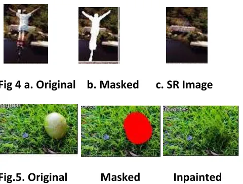
Figs. 4 and 5 illustrate the results of the proposed approach.
A down sampling factor of 4 in both directions is used. Pictures have a resolution varying in the range 420 × 380 to 720 × 512. Fig. 7(b) gives the inpainted low-resolution picture whereas the column (c) illustrates the final result. The proposed approach faithfully recovers the texture such as the grass, the sand and the snow. Structures are also well recovered. Fig. 8 presents more results which are visually plausible and pleasing in most of the cases. The less favourable results are obtained when the hole to be filled in is rather small. In this case it might be better to reduce the down sampling factor or even to perform the inpainting at the full resolution.
B. Parameters Analysis
Available Online at www.ijpret.com 1700
very simple since every pixel value in the final picture is achieved by either the average or the median operator
Î(∗)(px)= 1
M∑ Î
(i) M
i=1 (px) (8)
Î(∗)(px)= M E DMÎ(i)(px) (9)
The advantage of these operators is their simplicity. However they suffer from at least two main drawbacks. The average operator as well as the median one do not consider the neighbours of the current pixel to take a decision. Results might be more spatially coherent by considering the local
Fig 4 a. Original b. Masked c. SR Image
Fig.5. Original Masked Inpainted
Neighbourhood. In addition, the average operator inevitably introduces blur as illustrated by Fig. 5.
To cope with these problems, namely blur and spatial consistency of the final result, the combination is achieved by minimizing an objective function. Rather than using a global minimization that would solve exactly the problem, we use a Loopy Belief Propagation which in practice provides a good approximation of the problem to be solved. This approach is described in the next section.
Available Online at www.ijpret.com 1701
priority Belief Propagation in order to deal with this complexity bottleneck. Indeed, the number of labels in [23] is equal to the number of patches in the source region. Here the approach is simpler since the number of labels is rather small; a label is simply the index of the inpainted picture from which the patch is extracted. A finite set of labels L is then composed of M values (M = 13 here), going from 1 to M. This problem can be formalized with a Markov Random Field (MRF) G = (ν,) defined over the t lattice composed of pixels inside T. Edges are the four connected image grid graph centered on each node. We denote N4 this neighbourhood system. The labelling assigns a label l (l ∈ L) to each node/pixel px (px ∈ T) so that the total energy E of the MRF is minimized (we denote by l p the label of pixel Px ).
E(l) = ∑p∈vVd(lp)+ ∑(n,m)∈N4Vs(ln, lm) (10)
Where,
•Vd (l p) is called the label cost (or the data cost) [24]. This represents the cost of assigning a label l p to a pixel px .given by
Vd(lp) = ∑n∈∅∑u∈v{Î(l)(x + u) − Î(n)(x + u)}2 (11)
Where υ is a square neighbourhood (3 × 3) centered on the current pixel. The cost increases when the dissimilarity between the current patch and colocated patches in other inpainted pictures is high.
VI. CONCLUSION
A novel inpainting approach has been presented in this paper. The input picture is first down sampled and several in-paintings are performed. The low-resolution inpainted pictures are combined by globally minimizing an energy term. Once the combination is completed, a hierarchical single image super resolution method is applied to recover details at the native resolution. Experimental results on a wide variety of images have demonstrated the effectiveness of the proposed method.
REFERENCE:
Available Online at www.ijpret.com 1702
2. D. Tschumperlé and R. Deriche, “Vector-valued image regularization with PDEs: A common framework for different applications,” IEEE Trans. Pattern Anal. Mach. Intell., vol. 27, no. 4, pp. 506–517, Apr. 2005.
3. T. Chan and J. Shen, “Variational restoration of non-flat image features: Models and algorithms,” SIAM J. Appl. Math., vol. 61, no. 4, pp. 1338–1361, 2001.
4. A. Criminisi, P. Pérez, and K. Toyama, “Region filling and object removal by examplar-based image inpainting,” IEEE Trans. Image Process., vol. 13, no. 9, pp. 1200–1212, Sep.2004.
5. I. Drori, D. Cohen-Or, and H. Yeshurun, “Fragment-based image completion,” ACM Trans. Graph., vol. 22, no. 2003, pp. 303–312, 2003.
6. P. Harrison, “A non-hierarchical procedure for re- synthesis of complex texture,” in Proc. In Conf. Central Eur. Comput. Graph., Vis. Comput Vis., 2001, pp. 1–8.
7. C. Barnes, E. Shechtman, A. Finkelstein, and D. B. Goldman, “Patch Match: A randomize correspondence algorithm for structural image editing,” ACM Trans. Graph., vol. 28, no. 3, p. 24, Aug. 2009.
8. A. A. Efros and T. K. Leung, “Texture synthesis by non-parametric sampling,” in Proc. 7th IEEE Comput. Vis. Pattern Recognit., Sep. 1999, pp. 1033–1038.
9. O. Le Meur, J. Gautier, and C. Guillemot, “Examplar-based inpainting based on local geometry,” in Proc. 18th IEEE Int. Conf. Image Process. Sep. 2011, pp. 3401–3404.
10. O. Le Meur and C. Guillemot, “Super-resolution-based inpainting,” in Proc. 12th Eur. Conf. Comput. Vis., 2012, pp. 554–567.
11. S. Dai, M. Han, W. Xu, Y. Wu, Y. Gong, and A Katsaggelos, “SoftCuts: A soft edge smoothness prior for color image super-resolution,” IEEE Trans. Image Process., vol. 18, no. 5, pp. 969– 981, May 2009.
12. W. T. Freeman, T. R. Jones, and E. C. Pasztor, “Example-based super resolution,” IEEE Comput. Graph. Appl., vol. 22, no. 2, pp. 56–65,Mar.–Apr.02
13. D. Glasner, S. Bagon, and M. Irani, “Super- resolution from a single image,” in Proc. IEEE Int. Conf. Comput. Vis., vol. 10. Oct. 2009, pp. 349–356.
14. H. Chang, D.-Y. Yeung, and Y. Xiong, “Super-resolution through neighbour embedding,” in Proc. IEEE Comput. Vis. Pattern Recognit., vol. 1. Jun.–Jul. 2004, pp. 275–282.
15. Y. Wexler, E. Shechtman, and M. Irani, “Space time video completion,” in Proc. IEEE Comput. Vis. Pattern Recognit., Jun.–Jul. 2004, pp. I-120–I-127.
Available Online at www.ijpret.com 1703
17. S. Di Zenzo, “A note on the gradient of a multi-image,” Comput. Vis. Graph., Image Process., vol. 33, no. 1, pp. 116–125, 1986.J. Weickert, “Coherence-enhancing diffusion filtering,” Int. J. Comput Vis., vol. 32, nos. 2–3, pp. 111–127, 1999.
18. J. Kopf, W. Kienzle, S. Drucker, and S. B. Kang, “Quality prediction for image completion,” ACM Trans. Graph., vol. 31, no. 6, p. 131, 2012.
19. A. Bugeau, M. Bertalmío, V. Caselles, and G. Sapiro, “A comprehensive framework for Image inpainting,” IEEE Trans. Image Process., vol. 19, no. 10, pp. 2634–2644, Oct. 2010.
20. D. D. Lee and H. S. Seung, “Algorithms for non-negative matrix factorization,” in Advances in Neural Information Processing System. Cambridge, MA, USA: MIT Press, 2000.
21. A. Buades, B. Coll, and J. Morel, “A non-local algorithm for image denoising,” in Proc. IEEE Comput. Vis. Pattern Recognit., vol. 2. Jun. 2005, pp. 60–65.