T. Madhu
et al
, International Journal of Computer Science and Mobile Applications,
Vol.2 Issue. 10, October- 2014, pg. 22-28 ISSN: 2321-8363
F
AULT
C
URRENT INTERRUPTION IN A RADIAL
DISTRIBUTION SYSTEM BY USING THE
DVR
T. Madhu
1, V.K.R. Mohan Rao
2, Y.Rambabu
31
P.G Scholar, EEE, Holy Mary Institute of Technology and Sciences, Telangana State, India
2Associate Professor and HOD, EEE, Holy Mary Institute of Technology and Sciences,
Telangana State, India
3
Associate Professor, EEE, Holy Mary Institute of Technology and Sciences, Telangana State, India
ABSTRACT: With the increase in use of electronic equipments there has been rise in problems related to power quality. Power quality deals with utilization of electric energy from the distribution system successfully without interference or interruption. The various power quality disturbances are transients, interruptions, voltage sag, voltage swell, voltage collapse, harmonics etc. These power quality related problems can be solved with the help of various custom power devices. Dynamic voltage restorer (DVR) is a custom power device used for the compensation of voltage sag and swell. It can provide the most commercial solution to mitigation voltage sag by injecting voltage as well as power into the system. In this paper an overview of DVR, its components, functions, compensating techniques and control methods are reviewed in detail and the compensating techniques are compared.
Keywords: Power quality, Dynamic voltage restorer, control methods, compensating techniques
I. INTRODUCTION
T. Madhu
et al
, International Journal of Computer Science and Mobile Applications,
Vol.2 Issue. 10, October- 2014, pg. 22-28 ISSN: 2321-8363
II.CONTROL STRATEGY
Different type of voltage sag and load conditions can limit the possibility of compensating voltage sag. Therefore, the control strategy depends on the type of load characteristics. There are three different methods to inject DVR compensating voltage.
fig 1.0 Prefault compensation method
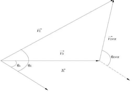
B. In-phase Compensation
In-phase voltage compensation method restores voltage to be in phase with the voltage sag. In other words, the phase angle will be same as the angle of sagged voltage while the voltage magnitude is restored to pre-fault value. Fig 3 shows the single-phase vector diagram for in-phase compensation method
Fig 2.0 In-phase compensation method
T. Madhu
et al
, International Journal of Computer Science and Mobile Applications,
Vol.2 Issue. 10, October- 2014, pg. 22-28 ISSN: 2321-8363
1. Pre-sag compensation method 2. In-phase compensation method
3. In-phase advanced compensation method
4. Voltage tolerance method with minimum energy injection
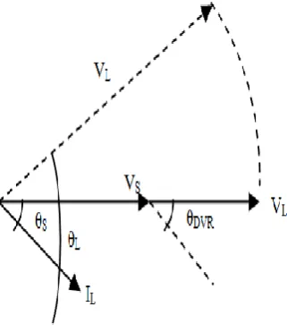
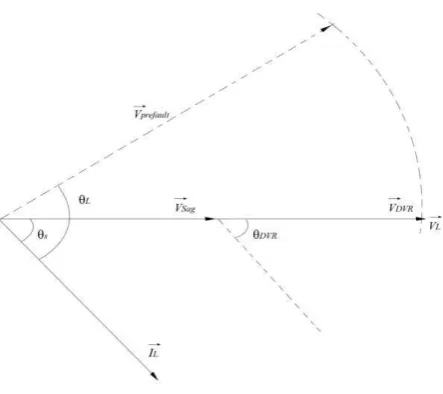
A Pre-Sag Compensation:
The sag method tracks the supply voltage continuously and compensates load voltage during fault to pre-fault condition When it detects any disturbances in supply voltage it injects the difference voltage between the sag or voltage at PCC and pre-fault condition, so that the load voltage can be restored back to the pre-fault condition. Compensation of voltage sags in the both phase angle and amplitude sensitive loads would be achieved by pre sag compensation method. In this method the injected active power cannot be controlled and it is determined by external conditions such as the type of faults and load conditions This method is achieved by using a fault detector to freeze the output from the Phase Locked Loop (PLL) circuit, when the fault occurs. The voltage of DVR is given as:
VDVR = Vprefault – Vsag
Fig 3 : Pre sag compensation
B. In phase Compensation method:
T. Madhu
et al
, International Journal of Computer Science and Mobile Applications,
Vol.2 Issue. 10, October- 2014, pg. 22-28 ISSN: 2321-8363
Fig 4 : In Phase compensation method
C. In Phase advanced compensation:
In this method the real power spent by the DVR is decreased by minimizing the power angle between the sag voltage and load current. In case of pre-sag and in-phase compensation method the active power is injected into the system during disturbances. The active power supply is limited stored energy in the DC links and this part is one of the most expensive parts of DVR. The minimization of injected energy is achieved by making the active power component zero by having the injection voltage phasor perpendicular to the load current phasor. In this method the values of load current and voltage are fixed in the system so we can change only the phase of the sag voltage. IPAC method uses only reactive power and unfortunately, not al1 the sags can be mitigated without real power, as a consequence, this method is only suitable for a limited range of sags.
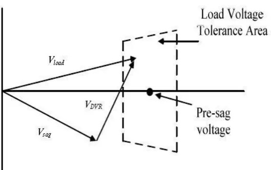
D. Voltage tolerance method with minimum energy injection:
T. Madhu
et al
, International Journal of Computer Science and Mobile Applications,
Vol.2 Issue. 10, October- 2014, pg. 22-28 ISSN: 2321-8363
T. Madhu
et al
, International Journal of Computer Science and Mobile Applications,
Vol.2 Issue. 10, October- 2014, pg. 22-28 ISSN: 2321-8363
IV.CONCLUSION
T. Madhu
et al
, International Journal of Computer Science and Mobile Applications,
Vol.2 Issue. 10, October- 2014, pg. 22-28 ISSN: 2321-8363
[5] J. V. Milanovic and C. P. Gupta, “Probabilistic of financial losses due to interruptions and voltage sags–Part I: The methodology,” IEEE Trans Power Del., vol. 21, no. 2, pp. 918-924, 2006.
[6] J. V. Milanovic and C. P. Gupta, “Probabilistic of financial losses due to interruptions and voltage sags–Part II: Practical implementation,” IEEE Trans Power Del., vol. 21, no. 2, pp. 925- 932, 2006.
[7] A. Ghosh and Gerard, “Power quality enhancement using custom power devices,” Kluwer Power Electronics and Power SystemSeries, 2002.
[8] A. Ghosh and G. Ledwich, “Compensation of distribution system voltage using DVR,” IEEE Trans. on Power Del., vol. 17, pp. 1030-1036, 2002.
[9] D. V. Hertem, M. Didden, J. Driesen, and R. Belmans, “Choosing the correct mitigation method against voltage dips and interruption: A customer-based approach,” IEEE Trans. on Power Delivery, vol. 22, no. 1, pp. 331-391, Jan 2007.
[10] S. S. Choi, J. D. Li and D. M. Vilathgamuwa, “Dynamic voltage restorating with minimum energy injection,” IEEE Trans. OnPower Sys., vol. 15, pp. 51-57, Feb 2000.
[11] M. R. Qader, M. H. J. Bollen, and R. N. Allan, “Stochastic prediction of voltage sags in a large transmission system,” IEEETrans. Industrial Applications, vol. 35, no. 1, pp. 152–162, Jan /Feb 1999.
[12] E. E. Juarez and A. Hernandez, “An analytical approach for stochastic assessment of balance and unbalanced voltage sags in large system,” IEEE Trans. Power Del., vol. 21, no. 3, pp. 1493- 1500, July 2006.
Authors Bibliography
Madhu Tanneru completed his B.Tech from prakasam engineering college, kanigiri road kandukur, prakasam dt AP university. i am currently working towards the m.tech degree in electrical engineering from holy mary institute of technology & science, jntu hyd, hyderabad, india.
R. MOHAN RAO received the M.Tech. degree in Power Electronics from J.N.T.U in the year 2006 from PRRM College, Shabad, R. R. Dist. Andhra Pradesh, India, B.Tech in EEE from J.N.T.U in the year 2002 from Viswanadha Institute of Technology and Management and Diploma in EEE from SBTET in 1997 from A.A.N.M. & V.V.R.S.R. Polytechnic College, Gudlavalleru, Andhra Pradesh, India . He has 07 years of Teaching Experience & 04 years of Industrial Experience. Currently working as HOD & Professor in Holy Mary Institute of Technology & Science, Bogaram, R.R. Dist, Hyderabad, and Andhra Pradesh, India in the Dept. of Electrical & Electronics Engg. His Interested areas are Power Systems, Power Electronics & Drives, FACTS, etc. He is a member in International Association of Engineers (IAENG).