Analysis of Energy Efficient Network
Beamforming Design
Using Power-Normalized SNR
Roopa.A.S 1, Dr.Hemanth Kumar.A.R2
P.G. Student, Department of Electronics Engineering, BIT Engineering College, Bengaluru, Karnataka, India1
Professor, Department of Electronics Engineering, BIT Engineering College, Bengaluru, Karnataka, India2
ABSTRACT: In this work, a novel efficiency measure is adopted for amplify-and-forward (AF) an relay network which is the received SNR per unit power. This efficiency measure is called as the power-normalized SNR (PN-SNR). We determine the PN-SNR maximization problems and investigate the network performance for several relay network scenarios with both SISO (Single Input Single Output) configuration and MIMO (Multiple Input Multiple Output) configuration. Initially, for single-relay networks with SISO configuration the PN-SNR for a given transmitter power is found using an optimal relay power control scheme that maximizes a PN-SNR. Then, for multi-relay networks for SISO configuration with a sum relay power constraint, we show that the PN-SNR optimization problem has a unique maximum, and thus using a gradient-ascent algorithm the globally optimal solution can be found. Then, for multi-relay networks for SISO configuration with an individual power constraint on each relay, we obtain a globally optimal solution for which an algorithm is proposed and also for a suboptimal solution we propose a low complexity algorithm. Finally, for single relay networks the comparisons of SISO and MIMO configurations is done and showed that for same transmitted power, PN-SNR is maximized and outage probability is minimized for MIMO configuration.
KEYWORDS:Relay network, Power-Normalized SNR, Efficiency, Power Control, Outage Probability.
I. INTRODUCTION
Popular efficiency measures include spectral efficiency (or capacity if the bandwidth is fixed) and energy efficiency. There has been a significant volume of literature addressing these two efficiency measures for various network configurations. Spectral efficiency is defined as the achievable transmission bit-rate and its maximization guarantees the highest amount of information flow for a fixed transmit power. But it does not consider how efficient the power is used in achieving the maximum. Energy efficiency is defined as the number of transmitted bits per unit energy or power. It is thus a natural efficiency measure. However for most communication systems, energy efficiency is maximized when the transmit power approaches 0, i.e., when the system works in the low SNR regime. To see this, we consider the simple point-to-point single-antenna system with transmit power P, unit-variance noise, and channel gain λ. The energy efficiency of the system is given as[ (1 + )]/ , which takes its maximum λ when P → 0. Hence, an energy efficiency- optimal scheme will trap the system in the low SNR regime, where the communication bit-rate and reliability can be low. In this work, the aforementioned limitations of spectral efficiency and energy efficiency measures has inspired us to study new efficiency metric, namely SNR-per-unit-power or power normalized SNR (PN-SNR), to design network beam forming algorithms and to evaluate the network efficiency. For a singleuser network, the PN-SNR is defined as
≜ / ……. (1)
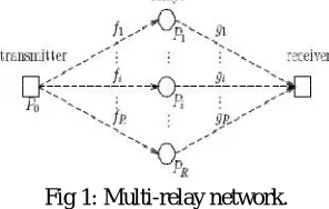
A general distributed network with one transmitter, one receiver and R relays, as depicted in Fig. 1 is considered. Each relay has only one single antenna which can be used for both transmission and reception. We denote the channel from the transmitter to the − ℎ relay as and the channel from the − ℎ relay to the receiver as . The assumption is that there is no direct link between the transmitter and the receiver and that and are i.i.d. complex Gaussian with zeromean and unit-variance, so the channel magnitudes follow Rayleigh distribution. All channels are assumed to be flat-fading channels. It is assumed that each relay knows its own channels, i.e., the − ℎ relay knows and , and the receiver knows all channels. The required channel state information at the receiver can be obtained via channel estimation. The − ℎ relay can obtain by training and by feedback.
Fig 1: Multi-relay network.
Let ≜ [ , . . . ] and ≜ [ , . . . ] , which are the transmitter-relay and relay-receiver channel vectors. We define the effective end-to-end channel vector between the transmitter and the receiver as ≜ . We herein consider a two-hop amplify-and-forward (AF) relaying protocol with relay beamforming, where the relays adjust the amplitudes and the phases of their received signals before forwarding them. During the first hop, the transmitter sends √ , where the information symbol s is randomly selected from the codebook S. We assume that s in the codebook are normalized as {|s| } = 1. Thus, the average power used at the transmitter is for each transmission. The signals received at the relays can be represented as
= + ……. (2)
where is the × 1 complex vector of the signals received by the relays and is the × 1complex vector of the relay noises. We assume that all noises are i.i.d. complex Gaussian random variables with zero-mean and unit-variance. In the second hop, the ℎ relay multiplies its received signal by a complex weight to adjust the phase and magnitude of the signal, and transmits the adjusted signal. All relays share the same channel and are assumed to be perfectly synchronized. The × 1 complex vector of the transmitted signals of all relays can then be expressed as
= ………. (3)
where ≜[ . . . ] is referred to as the beamforming vector. Denote the ℎ entry of as . The power consumed on the ℎ relay, denoted as , can be calculated, using (3), as
= {| | } = (1 + | | )| | ……. (4)
The signal received at the receiver, denoted as , can be written as
= ℎ + ( ) +
where the noise n at the receiver is assumed to be independent of , . . . , and is Gaussian distributed with zero mean and unit variance. With straightforward calculation, the end-to-end received SNR can be expressed as
=
| | …. (5)
≜ 1 + | | … … 1 + | |
The total transmit power consumed in the whole network is thus = + | | . According to our definition in (1), the PN-SNR of the relay network is
≜ =
| | | | …… (6)
Denote the amplitude and the phase of as and , respectively, i.e., = e . Let ≜ [ ··· ] ≜
[ ··· ] . Note that both | | and | | are independent of the phase vector . Thus, the denominator of given in (6) is independent of . It is obvious that the numerator is maximized when = −∠ℎ for any given α, where ℎ = is the ℎ entry of ℎ. With the optimal phase adjustment at the relays, the end-to-end received SNR in (5) reduces to
= α
|α | ……… (7)
and the PN-SNR in (6) reduces to
= α
|α | |α | ……. (8)
where ≜ [| | ··· | |] and ≜ [| |,···, | |].
In this work, is assumed to be fixed. Our design problem is to find the relay power control vector α such that the PN -SNR in (8) is maximized. It is conceivable that if we allow the transmitter power to be adaptive as well and consider the optimization of not only the relay power but also the transmitter power under a fixed total , a higher PN-SNR may be obtained. However, this formulation implies that the transmitter and relays can freely share power, which may not be practical for many distributed relay networks. Also, it causes extra computation or hardware burden on the transmitter in optimizing and adjusting the power. In this work, it is assumed that the transmitter has its own power source and fixed transmission power, while the relays can adjust their powers in cooperation for the highest efficiency.
III.EXPERIMENTAL RESULTS
A. Single-Relay Networks with SISO configuration For SISO Configuration:
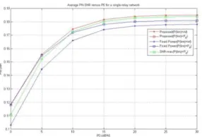
We simulate the average PN-SNR, end-to-end received SNR, and outage probability with threshold γth = 0dB for the proposed PN-SNR-maximizing scheme (denoted as “Proposed”), the SNR-maximizing scheme (denoted as “SNR-max”) and the fixed relay power scheme (denoted as “Fixed power”).
Fig. 2. Average PN-SNR versus P0 for a single-relay network.
Fig. 3. Average received SNR versus P0 for a single-relay network.
Fig. 3 shows the average end-to-end received SNR versus P0 for the three schemes. Our proposed scheme has comparable performance in average SNR with the fixed relay power scheme but it is inferior to the SNR-maximizing scheme.
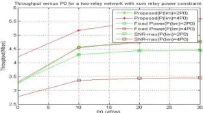
Fig. 4. Average Throughput versus P0 for a single-relay network.
Fig. 4 shows the average Throughput versus P0 for the three schemes. We can see that in the proposed PN-SNR maximizing scheme, the throughput increases as PR,lim increases. In the fixed relay power scheme, the throughput decreases as PR,lim increases. Among the three schemes, our proposed scheme always achieves the highest throughput.
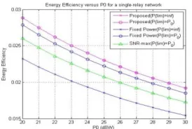
Fig. 5. Energy efficiency versus P0 for a single-relay network.
In Fig. 5, we evaluate the energy efficiency in bits per Joule of the three schemes. We observe that our proposed design achieves the best energy efficiency. However, the energy efficiency for all three schemes is low and is decreasing as P0 increases. Thus, as we have explained, to achieve high energy efficiency, the system needs to function in the low SNR regime, where the network SNR and throughput are low. This actually motivates our use of PN-SNR as efficiency measure.
B. Multi Relay Networks with a Sum Relay Power Constraint For SISO Configuration:
.
Fig. 6. Average PN-SNR versus the number of relays for multirelay networks with sum power constraint
Fig. 6 shows the average PN-SNR versus number of relays for the two schemes. In the proposed PN-SNR-maximizing scheme, the average PN-SNR increases linearly with the number of the relays. In the SNR maximizing scheme, however, the average PN-SNR increases with a significantly smaller rate and saturates as the number of the relays increases.
Fig .7. Average SNR versus PO for muti relay networks with sum power constraint
Fig. 7 shows the average end-to-end received SNR versus P0 for the three schemes. Our proposed scheme has comparable performance in average SNR with the fixed relay power scheme but it is inferior to the SNR-maximizing scheme
Fig .8. Average PN-SNR versus PO for muti relay networks with sum power constraint
Fig. 8 shows the average PN-SNR versus P0 for the three schemes. In the PN-SNR-maximizing scheme, the average PN-SNR slightly increases as PR,lim changes from 2P0 to 4P0. In the fixed relay power scheme, the average PN-SNR slightly decreases as PR,lim increases. In the SNR-maximizing scheme, the average PN-SNR sharply decreases as
PR,lim increases. Among the three schemes, the proposed scheme always achieves the highest PN-SNR.
PN-SNR slightly increases as PR,lim changes from 2P0 to 4P0. In the fixed relay power scheme, the average PN-SNR slightly decreases as PR,lim increases. In the SNR-maximizing scheme, the average PN-SNR sharply decreases as
PR,lim increases. Among the three schemes, the proposed scheme always achieves the highest PN-SNR.
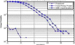
Fig .10. Outage probability versus PO for multi relay networks with sum power constraint
Fig. 10 shows the outage probability versus P0 for the three schemes. Note that for all three schemes, the outage probabilities decreases as PR,lim grows from 2P0 to 4P0.
C. Multi Relay Networks with Separate Relay Power Constraint For SISO Configuration :
In this subsection, we investigate the performance of multirelay networks with separate power constraints on the relays. We simulate the average PN-SNR and outage probability with threshold γth = 0 dB for the PN-SNR-maximizing scheme (denoted as “Proposed”) and compare them with the SNR-maximizing scheme (denoted as “SNR-max”).
Fig.11. Average PN-SNR versus PO for multi relay networks with separate relay power constraint
Fig. 11 shows the average PN-SNR versus P0 for the three schemes in a two-relay network. First we can see that the PN-SNR of the suboptimal solution is almost the same as the optimal solution. Also, the proposed PN-SNR-maximizing scheme outperforms the other two schemes in terms of the PNSNR. When P0 = 30 dBW, we can read from the plot that our proposed scheme is superior by 20.4% and 40% compared with the other two schemes.
Fig. 12. Outage probability versus PO for multi relay networks with separate relay power constraint
Fig. 12 shows the outage probability versus P0 for the three schemes. We can see that the proposed scheme is worse in outage probability than the SNR-maximizing scheme.
-5 0 5 10
10-3 10-2 10-1 100 P0(dBW) O u ta g e P ro b a b ili ty
P0 v/s Outage Probability for Sum Power Constraint Proposed(P(lim)=2P0) Proposed(P(lim)=4P0) Fixed Power(P(lim)=2P0) Fixed Power(P(lim)=4P0) SNR-max(P(lim)= 2P0) SNR-max(P(lim)= 4P0)
0 5 10 15 20 25 30
0. 1 0. 15 0. 2 0. 25 0. 3 0. 35 0. 4 0. 45
Average PN-SNR versus P0 for a two-relay network with separat e relay power const raint.
P0 (dBW) P N -S N R Proposed Fixed Power SNR-max
-5 0 5 10 15 20
10-3 10-2 10-1 100 P0(dBW ) O u ta g e P ro b a b ili ty
P0 v/s Outage Probability for Seperate Power Constraint
D. Comparision of SISO and MIMO configurations for Single Relay Networks:
We simulate the average PN-SNR, average SNR, average energy efficiency and outage probability for the proposed PN-SNR-maximizing scheme for SISO and MIMO configurations.
Fig.13. Average PN-SNR versus PO for single relay network for SISO and MIMO configurations
Fig. 13 shows the average PN-SNR versus P0 for the proposed scheme for both MIMO and SISO configurations. We can see that in the MIMO configuration, the PN-SNR increases as PR,lim increases. In the SISO configuration, the PN-SNR decreases as PR,lim increases. Our proposed scheme always achieves the highest PN-SNR for MIMO configuration.
Fig.14. Average SNR versus PO for single relay network for SISO and MIMO configurations
Fig. 14 shows the average end-to-end received SNR versus P0 for the two configurations. The average SNR in MIMO configuration is inferior to the SISO configuration.
Fig.15. Average energy efficiency versus PO for single relay network for SISO and MIMO configurations
In Fig.15, we evaluate the energy efficiency in bits per Joule of the two configurations. We observe that MIMO configuration achieves the best energy efficiency. Because at some Point SISO configuration will achieve highest energy efficiency but as the transmit power increases, energy efficiency certainly decreases. But in MIMO configuration the energy remains constant as the P0 increases.
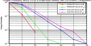
Fig.16. Outage Probability versus PO for single relay network for SISO and MIMO configurations
0 5 10 15 20 25 30
0.05 0. 1 0.15 0. 2 0.25 0. 3 0.35 0. 4 0.45 0. 5
Average PN-SNR ver sus P0 for a single-r elay network with SISO/MIMO configur at ions
P0 (dBW) P N-S NR MIMO(P(lim)= inf) MIMO(P(lim)= P 0) SISO(P(lim)= inf) SISO(P(lim)= P0)
0 5 10 15 20 25 30
-10 -5 0 5 10 15 20 25 30
Average SNR versus P0 for a single-relay network with SIS O/MIMO configurations
P0 (dBW )
A v e ra g e S N R MIMO(P(lim)=inf) MIMO(P(lim)=P0) SISO(P(lim)=inf) SISO(P(lim)=P0)
0 5 10 15 20 25 30
0.02 0.04 0.06 0.08 0.1 0.12 0.14 0.16 0.18
Average Energy Efficiency versus P0 for a s ingle-relay network with SISO/M IMO configurations
P0 (dBW )
E n e rg y E ff ic ie n c y MIMO(P(lim)=inf) MIMO(P(lim)=P0) SISO(P(lim)=inf) SISO(P(lim)=P0)
0 5 10 15 20 25 30
10-3 10-2 10-1 100
Outage Probability versus P0 for a single-relay network with SISO/ MIMO configurations
P0 (dBW )
worse in outage probability than the SISO configuration.
IV. CONCLUSION
we adopted a new metric, namely power normalized SNR (PN-SNR) to design efficient relay networks, and proposed an optimal relay power control scheme which maximizes this metric. Performance of the proposed scheme is analyzed and compared with existing schemes. Our studies showed that the proposed scheme achieves better PN-SNR while having comparable or even better outage performance compared with the fixed relay power scheme. Compared with the SNR-maximizing design, it has significantly higher PNSNR with moderate degradation in outage performance. The work discovered the potential of the PN-SNR as an efficiency measure in relay network design.
REFERENCES
[1] A. Sendonaris, E. Erkip, and B. Aazhang, “User cooperation diversity— part I: system description,” IEEE Trans. Commun., vol. 51, no. 11, pp. 1927–1938, Nov. 2003.
[2] C. J. K. Y. W. P. Hong, W. Huang, Cooperative Communications and Networking: Technologies and System Design. Springer, 2010.
[3] J. N. Laneman, D. N. C. Tse, and G.W.Wornell, “Cooperative diversity in wireless networks: efficient protocols and outage behavior,” IEEE Trans. Inf. Theory, vol. 50, no. 12, pp. 3062–3080, Dec. 2004.
[4] Y. Jing and H. Jafarkhani, “Network beamforming using relays with perfect channel information,” IEEE Trans. Inf. Theory, vol. 55, no. 6, pp. 2499–2517, June 2009.
[5] Y. Zhao, R. Adve, and T. J. Lim, “Improving amplify-and-forward relay networks: optimal power allocation versus selection,” IEEE Trans. Wireless Commun., vol. 6, no. 8, pp. 3114–3123, Aug. 2007.
[6] J. M. Paredes and A. B. Gershman, “Relay network beamforming and power control using maximization of mutual information,” IEEE Trans. Wireless Commun., vol. 10, no. 12, pp. 4356–4365, Dec. 2011.