i
tif c n
e C
i o
c n
S f
l e
a r
n e
o n
i c
t e
a 2
nr 0
et 1
1
n I
ISC 2011
Proceeding of the International Conference on Advanced Science,
Engineering and Information Technology 2011
Hotel Equatorial Bangi-Putrajaya, Malaysia, 14 - 15 January 2011
ISBN 978-983-42366-4-9
ISC 2011
International Conference on Advanced Science, Engineering and Information Technology
ICASEIT 2011
Cutting Edge Sciences for Future Sustainability
Hotel Equatorial Bangi-Putrajaya, Malaysia, 14 - 15 January 2011
SR
IE
AUNVI IT
NI
ESE
D K
O B
IN N
R AG
JA A
L S
A A
E N
P M
N A
A L
U A
T Y
A S
S A I
R
EP
N I
NOI TAI COSSA STNEDUTS NA ISENOD Organized by Indonesian Students Association Universiti Kebangsaan Malaysia Proceeding of the
Effectiveness of Truss Supporting During
Replacement of Damaged Column in a High-Rise
Frame Structure Building
Md. Kamrul Hassan
1, Md. Rabiul Alam
2, A. B. M. Amrul Kaish
3, and Muhammad Fauzi Mohd Zain
41&4
Dept. of Civil & Structural Engineeringt, Universiti Kebangsaan Malaysia Bangi-43600, Selangor, Malaysia
E-mail: [email protected], [email protected] 2&3
Dept. of Civil Engineeringt, Chittagong University of Engineering &Technology Chittagong-4349, Bangladesh
E-mail: [email protected]; [email protected]; [email protected] and [email protected]
Abstract— Truss supporting (TS) is a technique to support a building frame for replacing column when its stiffness reduces due to any kind of damage. This paper deals about the effectiveness of TS during replacement of damaged column in a high-rise frame structure building. For the case study of the effectiveness of TS, six columns that are damaged columns at different positions in the ground and first floors were taken into consideration. A suitable type of truss was modelled to transfer the load of damaged column to the lower column just below the damaged column. The numerical analysis of the 2-D frame with undamaged columns, damaged column and damaged column with truss supporting, was carried out using finite element software STAAD Pro 2004. The deflection, axial force, shear force and bending moment of the structural elements (beam & column) for TS case were obtained almost same as their design values.
Keywords— Truss Supporting, Numerical Analysis, Column Replacement and Frame Structure.
I. INTRODUCTION
For high-rise building, column is one of the most important structural elements, which is designed to support the compressive load and bending moment [1]. When columns of reinforced concrete (RC) frame building damage due to the effect of wind load or earthquake load or any other reasons, it is important to replace the entire damaged columns of the building especially for high-rise frame building during further servicing of structure. When a column damages, the beams over it get unsupported and its span will act as a span equal to twice the original beam span [2]. In this condition, a large positive moment develops at the centre of new beam and also negative moments at the ends of the beam rise up due to the upper column concentrated load and the new beam span. Another major problem is that the load of the damaged column transfers through the nearest columns, causing high axial load on
those columns. As a result, bursting of those columns may occur if the load exceeds its carrying capacity [3]. Therefore, total collapse of the frame structure building could happen in a minute.
T
o replace a column, propping & supporting techniquesII. ADVANTAGES OF TRUSS SUPPORTING OVER ‘PROPPING AND SUPPORTING’
Propping and supporting in a structure is used to relief the over burden stresses and deflections during the retrofitting work of any deteriorated structure [2, 3, 4, 5]. Props/supports are to be made of built up structural sections (tubular steel) of adequate capacity to be able to resist the total beam reactions from all upper stories. For propping the column at top, bottom or any intermediate column of the stories, props are provided at all stories below all beams meeting the column [4]. All props should be at the same position in all stories of building. Sequence of props/supports fixing would be 1-2-3-4 i.e. from lower to upper most story. And the sequence of props/supports removal would be 4-3-2-1 i.e. from topmost story to lower story [1]. Sometimes only vertical props/supports sitting on some beams and slabs may not be enough. For those cases diagonal bracing should also be considered to transfer the load to the adjacent [6]. In case of “truss supporting” it is needed only three stories such as damaged column level and above and below of that level. Retrofitting of joint can be done more easily by modelling a suitable truss than propping.
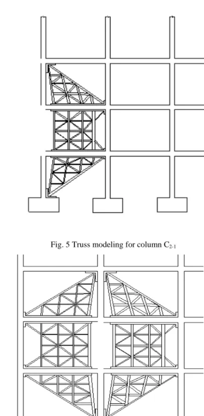
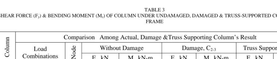
III. PROPOSED MODEL FOR TRUSS SUPPORTING
There are no definite rules of a truss modeling for supporting a frame. Many factors govern in a truss modeling for a frame such as; types of frame, loading condition, load distribution area of the modeled truss and type of occupancy, etc. Suitable types of trusses are modeled to relief the over burden stresses and strains during the retrofitting of high-rise frame structured building. Different types of trusses were modeled for replacement of column at different positions. The truss supporting systems, which are proposed in this study, are shown in the Figs. 1 to 4. Truss model for columns C1-3 and C2-3 is considered as same as truss model for column C1-2 and C2-2. Different size I-sections & L-sections are used to model truss members for transferring damaged column load to other nearest columns.
IV. STATEMENT OF HIGH-RISE BUILDING CONSIDERED IN THIS ANALYSIS
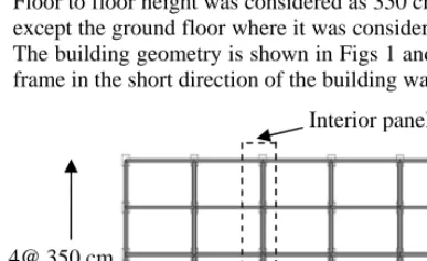
For a parametric study, one interior panel of a reference model of a 25-storied building of 4 x 5 bays was considered. Floor to floor height was considered as 350 cm for all stories except the ground floor where it was considered as 365.7 cm. The building geometry is shown in Figs 1 and 2. An interior frame in the short direction of the building was considered
Fig 1: Plan of the reference model
for the analysis since frame in this direction is found to be more vulnerable than other direction. Six damaged columns such as (C1-1, C1-2, C1-3, C2-1, C2-2, C2-3,)at different locations, which were considered for case studies, are shown in Fig. 2.
Fig. 2 Elevation of reference model of an interior panel
Fig. 3 Truss modeling for column C1-1
Fig. 4 Truss modeling for column C1-2
Interior panel
5@ 365.7 cm 4@ 350 cm
C1-1
C2-1
C1-2
C2-2
Fig. 5 Truss modeling for column C2-1
Fig. 6 Truss modeling for column C2-2
A. Finite Element Analysis
Finite element analysis of high-rise frame structure building with or without damaged columns and truss supporting was carried out using finite element software STAAD Pro. A total number of six damaged columns at different locations shown in Fig. 2 were. different locations shown in Fig. 2 were taken into consideration for the case study. For each case the frame was analyzed in three different conditions such as (1) frame without damage; (2) frame with damaged column and (3) frame with truss supporting (shown in Fig 7).
In all cases of the analysis, the cross-sections of beam and column were considered as 25.4 cm x 30.48 cm and 60.96 cm x 30.48 cm, respectively. The young’s modulus of elasticity and density of the concrete and steel materials
were considered as 21.72 kN/mm2 and 200 kN/mm2 and 2.4
gm/cm3 and 7.83 gm/cm3, respectively. The Poisson’s ratio
was set as 0.17 and 0.3 for concrete and steel, respectively.
Gravity load such as dead load (1.92 kN/m2), floor finish
(1.44 kN/m2) and live load (1.92 kN/m2) and lateral load
(wind) were considered. Lateral load as shown in Table 1, was calculated based on the wind velocity of 210 kmph.
Table 1
WIND LOAD AT DIFFERENT HEIGHTS OF RC FRAME STRUCTURE (UNIT: HEIGHT IN METER)
Fig. 7 Close view of the column and beam numbering of the actual frame Wind Load Calculation
Height Pressure (N/m2
) Point Load, kN
3.66 0.127 27.66
6.71 0.138 29.97
9.76 0.157 34.15
12.80 0.172 37.39
15.85 0.185 40.14
18.90 0.196 42.64
21.95 0.207 44.82
25.00 0.216 46.82
28.05 0.225 48.76
31.10 0.232 50.44
34.15 0.24 52.00
37.20 0.247 53.56
40.24 0.254 55.12
43.29 0.26 56.43
46.34 0.266 57.75
49.39 0.272 59.06
52.44 0.278 60.24
55.49 0.283 61.43
58.54 0.287 62.18
61.59 0.294 63.74
64.63 0.299 64.80
67.68 0.304 65.86
70.73 0.308 66.73
73.78 0.312 67.80
76.83 0.317 34.42
Two-noded beam elements with three dofs at each node were used to discretize the assumed interior panel. A total number of 225 beam elements were employed to model the panel. Two-noded bar elements were used to model the truss used in this study. At the interface of concrete and steel it is assumed that same strain will develop under the applied load.
V. RESULTS & DISCUSSION
In this study, the effectiveness of truss supporting was determined by comparing bending moment, shear force & deflection of beams and columns of RC frame high-rise building under the conditions of collapsed column with or without truss supporting. In all cases, bending moment, shear force & deflection values were calculated in the local coordinate system. All results based on the two load combination A = 1.2 DL +1.0 LL+ 1.6 WL (DL = dead load, LL = live load, WL = wind load, wind flow from left to right) and B = 1.2 DL + 1.0 LL + 1.6 WL (wind flow from right to left) were taken directly from STAAD Pro (2004) finite element analysis software. The shear forces and bending moments obtained in the beams and columns and axial forces in foundation for A & B load combination system and the three conditions of analysis (frame without damaged column, frame with damaged column and frame with truss supporting) are given in appendix as Table 6. When damage develops in the column, the nearest beams and columns of damaged column are normally affected more than the other one during the load acting on the structure. Therefore, the beams and columns, which are very close to the damaged column, are only taken into consideration in this comparison. From Table 2 it is observed that the shear
force, Fy (y-direction) and bending moment, Mz (about
z-direction) in beam 10 (beam numbering is shown in Fig. 7) at damaged condition of the column C2-3, are 523.94 kN and 1786.36 kN-m, respectively, which are greater than the values obtained from undamaged condition of the frame. However, when truss supporting was applied for the replacement of column C2-3, the shear force and bending moment values for the beam 10 were obtained as 132.17, kN and 139.75, kN-m respectively which are less than that of shear force (523.94 kN) and bending moment (1786.36 kN-m) of the beam 10 in actual frame. It is also seen that shear force and bending moment developed in beams 11, 12, 20 and 21 which are closed to the damaged column for truss supporting condition does not exceed the design shear force and bending moment of those beam at undamaged condition of the frame. This means that beams that are very close to the damaged column are safe if truss support is provided during replacing the damaged column.
From Table 3 it is observed that the maximum axial force, Fx and bending moment, Mz developed in column 6 at damaged condition of the column C2-3 , are 7309.34 kN and 5632.90 kN-m respectively. At undamaged condition, these values are 5640.75 kN and 1942.83 kN-m. And at truss supporting condition, these values are 5632.90 kN and 961.15 kN-m. From these results it is seen that the axial force of the column 6 at damage condition of the column
C2-3, is greater than that of undamaged condition. However, it
seems that bending moments of the column 6 obtained in both damaged and undamaged cases are close to each other. Maximum variation of bending moments in damage and undamaged cases is found to be 3.6%. Consideration of
TABLE 2
SHEAR FORCE (Fy) & BENDING MOMENT (Mz) OF BEAM UNDER UNDAMAGED, DAMAGED & TRUSS-SUPPORTED CONDITIONS OF FRAME.
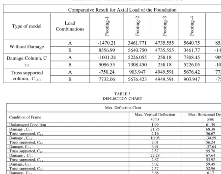
TABLE 3
SHEAR FORCE (Fy) & BENDING MOMENT (Mz) OF COLUMN UNDER UNDAMAGED, DAMAGED & TRUSS-SUPPORTED CONDITIONS OF
FRAME
Co
lu
mn Comparison Among Actual, Damage &Truss Supporting Column’s Result
Load
Combinations Node
Without Damage Damage, C2-3 Truss Supported, C2-3
Fy, kN Mz, kN-m Fy, kN Mz, kN-m Fy, kN Mz,
kN-6
A 2 3461.59 -1942.83 5226.95 -1786.36 903.96 24.20
7 -3418.34 -338.37 -5185.92 -568.13 -860.60 -168.03
B 2 5640.75 1942.42 7309.34 1776.84 5632.90 961.15
7 -5596.16 332.39 -7268.32 640.31 -5589.47 -551.27
Be
am
Comparison Among Actual, Damage &Truss Supporting Beam's Result
Load
Combinations Node
Without Damage Damage, C2-3 Truss Supported, C2-3
Fy ,Kn Mz, kN-m Fy, kN Mz, kN-m Fy, kN Mz, kN-m
10
A 6 -150.27 380.93 -153.13 386.64 75.75 -36.16
7 318.47 -476.23 321.41 -481.39 92.54 -66.89
B 6 324.67 -494.03 342.01 -523.94 132.17 -139.75
TABLE 4
AXIAL LOAD ON THE FOUNDATION (ALL DATA ARE IN kN)
TABLE 5 DEFLECTION CHART
Max. Deflection Chart
Condition of Frame Max. Vertical Deflection (cm) Max. Horizontal Deflection (cm)
Undamaged Condition 1.99 61.39
Damage , C1-1 21.95 68.38
Truss supported, C1-1 2.16 56.67
Damage , C1-2 10.05 134.59
Truss supported, C1-2 2.01 56.24
Damage, C1-3 6.91 137.64
Truss supported, C1-3 2.57 55.78
Damage , C2-1 22.28 67.64
Truss supported, C2-1 2.67 53.92
Damage, C2-2 5.02 59.49
Truss supported, C2-2 2.57 52.96
Damage, C2-3 3.68 61.7
Truss supported, C2-3 2.54 52.32
Max. allowable deflection 1.99 61.39
Deflection at damage condition 21.95 137.64
Deflection at truss supported condition 2.67 56.67
column as an axially loaded member could be the reason for this. From the analysis, it is seen that when truss supporting is provided for replacing damaged column C2-3, the axial force and bending moment of the columns such as column 8, 15 and 18 do not exceed the design axial force and bending moment of those column at the actual frame. This means that columns, which are close to the damaged column C2-3 are also safe when truss supporting is provided for replacing damaged column.
Table 4 shows reaction forces of different footings of the building, when column C1-1 is considered as damaged column. From this Table it is seen that the maximum reaction force developed in the footing 1 at undamaged condition is found as 8556.9 kN. At damage condition this reaction force is found as 9096.55 kN and in case of truss supporting this force is found as 7732.06 kN. For footing 2, the reaction forces at undamaged, damaged and truss supporting cases are found as 5640.75 kN, 7308.45 kN and 5676.423 kN, respectively. For footing 3, these values are found as 4735.55 kN, 258.18 kN and 4949.59 kN, respectively, and for footing 4 these values are found as 8556.99 kN, 9096.55 Kn and 7732.06 kN, respectively and also for footing 5, these values are found as 8556.9 kN, 9096.55 kN and 7732.06 kN. It is seen from these results that the reaction forces of the footing 1, footing 2, footing 4
and footing 5 at damage condition of the column C2-3, are increased and for footing 3, it is decreased because the load which transferred through the damage column, distributed to the nearest columns. But, in the truss supporting condition, the reaction force of the all footings is almost same of the original frame condition. From the summary results of Table 6, it is seen that the maximum reaction force of the footings at damage condition can be reduced by applying the truss supporting during the replacement of damaged column. Table 5 shows the maximum vertical and horizontal deflections of the frame at undamaged, damage and truss supporting condition. When frame is analyzed under undamaged condition based on the loading combinations, the maximum vertical and horizontal deflections at the top of the frame were found as 1.99 cm and 61.39 cm. But in the case of damaged condition, the maximum vertical and horizontal deflections are found as 3.68 cm and 61.70 cm respectively. From these results, it is seen that the vertical and horizontal deflections at damaged condition are found higher than that of the undamaged state of frame. However, when truss support was provided for the replacement of the damaged column C2-3, the maximum vertical and horizontal deflections at the top of the frame were found 2.54 cm and 52.32cm, which are lower than the damaged state of the frame.
Comparative Result for Axial Load of the Foundation
Type of model Load
Combinations
Fo
o
tin
g
-1
Fo
o
tin
g
-2
Fo
o
tin
g
-3
Fo
o
tin
g
-4
Fo
o
tin
g
-5
Without Damage A -1470.21 3461.771 4735.555 5640.75 8556.99
B 8556.99 5640.750 4735.555 3461.77 -1470.21
Damage Column, C 2-3
A -1001.24 5226.055 258.18 7308.45 9096.55
B 9096.55 7308.450 258.18 5226.05 -1001.24
Truss supported column, C 2-3
A -750.24 903.947 4949.591 5676.42 7732.06
VI. CONCLUSION
In this paper, truss supporting is proposed to support a frame structure high-rise building during replacement of damaged column. To verify the effectiveness of the truss supporting in the replacement of damaged column, numerical analysis of the supported frame structure with different conditions (undamaged frame, frame with damaged columns at different locations and frame with truss supporting at the location of damaged column) was carried out using finite element software STAAD Pro - 2004. The results obtained from this analysis it is seen that the maximum moments developed in beams just above the damaged column exceed the design moment of the same beams obtained from the analysis of actual frame without any damaged column in the frame. However, when truss supporting is provided for the replacement of column, the moment of the same beams does not exceed the design moment. Similarly, shear force in the beams just above the damaged column obtained at truss supporting condition does not exceed the design shear force of the actual frame. This means that beams just above the damaged column are safe if a proper truss supporting is provided during replacing damaged column. In the case of other structural element such as columns, it is observed that large axial force developed at the columns that are close to the damaged column. If truss supporting is provided, the axial forces of those columns are minimized (see Table-8). Therefore, columns that are close to the damaged column could be made safe by truss supporting. Foundation load could exceed
their design load due to self weight of supported truss. However it can be minimized by proper designing of truss member and using of high strength material in making truss member. Maximum horizontal and vertical deflections (see Table-9) were found within their allowable limit in the case of “Truss supporting”
ACKNOWLEDGEMENTS
The authors would like to mention that this paper would not submit in any conference paper.
REFERENCES
[1] Taranath B.S. (1988) “Structural Analysis and Design of Tall
Buildings”. McGraw-Hill Book Company.
[2] Chapter 6 (Rehabilitation & Retrofitting Methods), Page: 1 to
VI-37) of “Handbook on Repair & Rehabilitation of RCC Buildings”–
Central Public Works Department. Govt. Of India, Published in 2002.
[3] “Evaluation and repair of concrete structures”-U.S. army corps of
engineers,Washington, DC 20314-1000, Manual No. 1110-2-2002.
[4] “National Earthquake Hazards Reduction Program (NEHRP) guidelines for the seismic rehabilitation of buildings”‐ (FEMA Publication 273, Published in October 1997, Washington, D.C.).
[5] Aoyama, H. [19861, “Seismic Strengthening of Existing Reinforced
Concrete Buildings in Japan”, Department of Architecture, Faculty of Engineering, The University of Tokyo, Japan, September.
[6] Higashi, Y., Endo, T., and Shimizu, Y. [1981], “Experimental
Studies on Retrofitting of Reinforced Concrete Structural Members”, Proceedings of the Second Seminar on Repair and Retrofit of Structures, pp. 126-155, University of Michigan, Ann Arbor, MI.
TABLE 6
COMPARATIVE RESULTS OF AXIAL LOAD ON THE FOUNDATION
Type of model Load Combinations
F
o
o
ti
n
g-1
F
o
o
ti
n
g-2
F
o
o
ti
n
g-3
F
o
o
ti
n
g-4
F
o
o
ti
n
g-5
Without Damage A -1470.21 3461.77 4735.55 5640.75 8557
B 8557 5640.75 4735.55 3461.77 -1470.21
Damage , C 1-1 A 0 1843.3 4472.47 5778.98 9239.24
B 0 14518.8 6006.4 3359.21 -4645.48
Truss supported C 1-1 A -2507.79 5600.62 4748.93 5618.45 8106.63
B 8597.13 1455.14 4561.65 3467.21 -943.01
Damage, C 1-1 A -706.01 0 5591.7 5016.48 8628.34
B 11040.71 0 6595 3367.51 -2471.67
Truss supported, C 1-2 A -2719.42 3110.66 4690.96 5591.7 8075.41
B 8632.8 5676.42 2456.83 3425.47 -994.02
Damage column, C 1-3 A -2205.24 5185.92 0 6652.96 8895.89
B 8895.89 6652.96 0 5185.92 -2205.24
Truss supported, C 1-3 A -1010.92 1314.18 4641.91 5359.83 8084.33
B 8084.33 5359.83 4820.28 1314.18 -1011.14
Damage, C 2-1 A -90.43 1991.56 4485.85 5778.98 11856.72
B 438.69 15183.2 6965.1 3354.8 -462.85
Truss supported, C 2-1 A -5949.32 5596.16 4753.39 5600.62 7821.25
B 8191.35 7584.91 4339.94 3456.64 -601.09
Damage, C 2-2 A 227.95 239.05 5961.8 5899.38 8561.45
B 11361.76 275.44 6924.97 3887.52 -1558.76
Truss supported, C 2-2 A -2886.73 2987.19 4659.75 5493.6 7740.98
B 8186.89 5729.93 1742.48 3356.8 -655.44
Damage Column, C 2-3 A -1001.24 5226.05 258.18 7308.45 9096.55
B 9096.55 7308.45 258.18 5226.05 -1001.24
Truss supported, C 2-3 A -750.24 903.95 4949.59 5676.42 7732.06
B 7732.06 5676.42 4949.59 903.95 -750.24
Max. load at actual condition 8557 5640.75 4735.55 5640.75 8557
Max. load at damage condition 11361.76 15183.2 6965.1 7308.45 11856.72