Please cite this article as: H. Kermani, F. Behnamfar, V. Morsali,Seismic Design of Steel Structures Based on Ductility, International Journal of Engineering (IJE), TRANSACTIONS A: Basics Vol. 29, No. 1, (January 2016) 23-30
International Journal of Engineering
J o u r n a l H o m e p a g e : w w w . i j e . i rSeismic Design of Steel Structures Based on Ductility
H. Kermania, F. Behnamfar*b, V. Morsalic
aSenior Structural Engineer, Tehran, Iran
bDepartment of Civil Engineering, Isfahan University of Technology, Esfahan 8415683111, Iran cDepartment of Civil Engineering, Saghez Branch, Islamic Azad University, Saghez , Iran
P A P E R I N F O
Paper history:
Received 30 July 2015
Received in revised form 13 December 2015 Accepted 24 December 2015
Keywords: Ductility
Nonlinear Dynamic Analysis Seismic Design
A B S T R A C T
In this paper a simple tool for seismic design of steel structures for a selected ductility level is presented. For this purpose, a consistent set of earthquakes is selected and sorted based on the maximum acceleration of ground surface. The selected records are applied as the base motion to a single-degree-of-freedom system with strain hardening and the maximum response acceleration is determined for three levels of ductility. The response results of the nonlinear dynamic analysis are presented in the shape of the maximum acceleration of the system versus the peak ground acceleration for a certain ductility demand. Using these graphs, the maximum acceleration and base shear of the system are calculated by accounting for its nonlinear behavior, hence eliminating the need for the response modification factor. This is the main advantage of the presented diagrams for nonlinear seismic design of steel moment frames.
doi: 10.5829/idosi.ije.2016.29.01a.04
1. INTRODUCTION1
Seismic design of structures in the framework of earthquake engineering building codes is generally based on determining maximum (artificial) inertial forces and applying these forces as external loads to the structural system. The internal structural forces resulted from the above analysis are deemed to be equivalent to the maximum forces induced in the system in the design earthquake. For determination of these design forces, factors including indeterminacy and ductility of system are accounted for. The effect of indeterminacy is included using an overstrength factor representing the ratio of the ultimate lateral strength of system to the yield strength.
The ductility of system is represented by the so-called “behavior factor for ductility” showing the ratio of the required lateral elastic strength to the ultimate lateral strength of system. Using the above two effects, it will be possible to considerably reduce the maximum accelerations by dividing them by the above factors. This way maximum accelerations of the system,
1*Corresponding Author’s Email:[email protected], (F. Behnamfar)
calculated assuming elastic behavior for simplicity, are reduced to a level of the corresponding lateral strength that can be practically provided for.
An approximate procedure currently suggested in related codes like Standard 2800 [1] is using a displacement amplification factor. This amplifier is to be multiplied to the displacements resulted from the linear analysis to approximately calculate the real nonlinear displacements. Numerical values of the displacement amplification factor, Cd, have been presented for each structural system in, e.g., uniform building code (UBC) 97 [2] and international building code (IBC) 2010 [3]. The approximate displacements calculated as such are compared with the admissible code prescribed values. The acceptable values are functions of the use and importance level of building [3]. Although, no definite criteria exists yet in design codes for the quantity and extent of the seismic damage admitted as above in a structure. In the above method, the principle is calculating the design forces; and the other responses are determined based on them. For this reason, the method is known as the force method. Meanwhile, as an exception, the seismic code of New Zealand [4] has adopted a different approach and calculates the base shear and lateral forces based on the ductility level of the considered structural system. Values of the ductility factor, as the ratio of the maximum lateral displacement of a system to its yield displacement, have been suggested in this code for various lateral load bearing systems.
In the above method, the basis is selecting a ductility factor or equivalently, the inevitable level of seismic damage, and calculating the design forces based on it. This is called the displacement method. Of course, also in the above building code, the ductility factors are presented as prescribed values and it is not known which are corresponding to what level of structural damage in the design earthquake.
In the same line, Priestley and his co-workers [5] developed the concept of designing structures to achieve a specified performance limit state that was first introduced, in New Zealand, in 1993. The method named DDBD was an alternative to the force-based code approaches. In their study, the aspects related to characterization of seismic input for displacement-based design, and to structural representation for design verification using time-history analysis, have also received special attention. In another work [6], a design method was proposed for moment frames based on achieving a prescribed performance level. Performance control method (PC) was suggested as a design strategy in which the strength, stiffness and other characteristics of groups of members were introduced in accordance with predetermined objectives rather than investigated with respect to certain design criteria. The aim of this methodology was to enable engineers to predict and control structural damage at preselected response stages such as at first yield, any fraction of the failure load or allowable drift ratio, etc.
Also, Zhai and his colleagues [7] calculated a ratio for the level of damage in the design process. The constant inelastic displacement ratios were used to allow evaluation of maximum inelastic displacement demand for structures with constant damage performance. The influences of period of vibration, levels of damage, site conditions, earthquake magnitude, rupture distance, post-yield stiffness, stiffness degradation, strength deterioration, and ductility factor on the damage index were evaluated and discussed statistically. A simplified expression was also proposed for calculation of the damage inelastic displacement ratios.
Considering the above-mentioned two visions, an approach based on the displacement method is followed in this paper and an alternative method is presented for design of structures, especially steel structures, based on ductility. The suggested method is based on calculating diagrams of maximum acceleration of a nonlinear single-degree-of-freedom (SDF) system with known initial period and ductility factors under consistent earthquakes.
In the following sections of the paper, the nonlinear SDF system and the accelerogams are introduced and then these diagrams are presented.
2. THE NONLINEAR SINGLE DEGREE OF FREEDOM SYSTEM
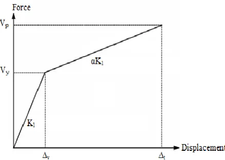
For determining the structural response with considering its inelastic behavior in an earthquake, a bilinear SDF system is taken into account. The diagram of the lateral behavior of this system is shown in Figure 1. The above SDF system is used to determine the spectral responses. In the simplest case, the tangent of the second branch of the behavior diagram can be assumed to be zero.
In practice, for moment frame systems with large indeterminacy, this tangent is positive and for systems with brittle behavior such as building frames with only tension braces, the tangent will be negative. The parameters determining the behavior diagram of Figure 1 are: The initial stiffness of the system K1 or its associated period T, the viscous damping ratio ξ, the yield displacement ∆y or its corresponding yield base shear Vy, the secondary system stiffness αK1 in which α is ratio of the secondary to the initial stiffness values, and the maximum displacement of the system ∆t. As such, the ductility factor of the system is defined with the following equation:
(1)
It is to be noted that the factor α can be assumed to be equal to 0.03 for moment frame steel structures with enough indeterminacy [8]. Also, the damping ratio is assumed to be 0.05.
3. THE UTILIZED ACCELEROGRAMS
Since the purpose is to present the suggested method in comparison with the current code-based routine, a suite of consistent earthquake records is used. These earthquake accelerograms have been recorded by the stations of the Building and Housing Research Center in the time period 1975-1995, and are available on the webpage of the center [9]. The above earthquakes, all of which have been recorded on firm soil, are composed of 13 pairs of perpendicular components. Both of the earthquake components will be used in the analysis. The earthquakes have been selected such that at least one of their horizontal components has a peak ground acceleration (PGA) larger than 0.1g.
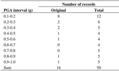
In the next step, the records are sorted in consecutive 0.1g intervals based on their PGA’s. Since the number of records was small in some intervals, some of the records were scaled to produce the records with appropriate PGA’s. To retain consistency of the scaled records with reality, the scale factor was kept between 0.5 and 2 [10]. As a result, at least 4 accelerograms were collected for each interval to be applied to the SDF system. Numbers of accelerograms in each interval including the original (needing no scaling) and original plus scaled records are mentioned in Table 1. Therefore, the total number of the records for the dynamic analysis is 50.
4. DYNAMIC ANALYSIS OF THE SDF SYSTEM
The SDF system with the characteristics shown in Figure 1 is subjected to the earthquake records of Table
2. For nonlinear analysis of this simple system use is made of NONLIN [11]. This software can be used to produce elastic and inelastic spectra with various ductility values. The period associated with the elastic behavior of the system, T, is considered to vary from 0.1 s to 1.0 s with 0.1 s increments. These values are approximately equivalent to the fundamental period of 1 to 10-story steel moment frames and cover the usual height range of these buildings. The ductility factor of this system, corresponding to its expected ductility in earthquake, is presumed to be μ=1, 1.5, 2, 2.5 with μ=1 showing elastic behavior. The nonlinear dynamic analysis of the system (for μ>1) is implemented iteration. In this analysis, first a ∆y is assumed and then ∆t is calculated with the nonlinear analysis. If ratio of ∆t to ∆y is not equal to the assumed μ, ∆t will be varied until convergency is satisfied. The maximum acceleration of the system in this case is stored as the peak acceleration corresponding to the presumed ductility. Value of the time increment in the linear and nonlinear dynamic analysis is taken as 0.01 s that is not larger than one-tenth of the natural period even for the shortest period system in this study. Smaller values of the increment were also evaluated and proved to be redundant for the systems under study.
Afterwards, the maximum acceleration of the system is calculated versus peak earthquake acceleration for different periods and ductility factors.
After accomplishing such a calculation, it is observed that with the increase of the peak earthquake acceleration, the maximum acceleration of the system also increases. Of course, it is seen that augmenting μ results in reduction of response increase rate compared to the increase rate of earthquake acceleration. Also, for each period, increase of the ductility factor results on average in reduction of the system’s maximum acceleration. All of the above observations are in line and expectable. The above facts can be more clearly seen in Figure 2 where variation of the absolutely maximum spectral acceleration is shown against the period and ductility factor.
TABLE 1. Number of records in each interval
PGA interval (g)
Number of records
Original Total
0.1-0.2 8 12
0.2-0.3 2 6
0.3-0.4 2 5
0.4-0.5 1 4
0.5-0.6 1 4
0.6-0.7 0 4
0.7-0.8 0 5
0.8-0.9 1 5
0.9-1.0 1 5
5. DETERMINATION OF THE SPECTRAL ACCELERATION MODIFICATION FACTOR FOR NONLINEAR BEHAVIOR
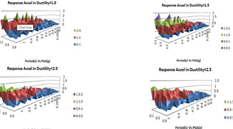
The average and average plus one standard deviation (σ) of Sa for each peak ground acceleration interval and for different ductility factors are depicted versus the natural period in Figures 3 and 4, respectively.
Using Figures 3 and 4, maximum acceleration of the system can be calculated for various ductility factors and natural periods as a function of PGA. To make this procedure similar to the equivalent static or the spectrum analysis method of the current codes and simplify the computations, a modification factor for
converting the elastic maximum acceleration to the one considering the nonlinear behavior of the system, or in brief, the nonlinear acceleration factor, ap, is introduced and calculated in this section.
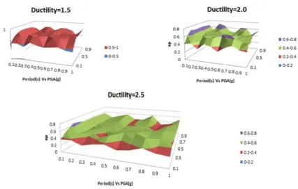
Value of this factor is determined by dividing the maximum acceleration of the system with a certain period and ductility factor in each PGA interval to the same quantity for μ=1 in Figures 3 and 4.
The nonlinear acceleration factors corresponding to the average and average+1σ levels are presented in Figures 5 and 6, respectively. It is noted that these factors are first calculated for the average of PGA’s of each interval and then are determined for PGA= (0.1-1.0) g with linear interpolation.
Figure 2. Absolutely maximum acceleration of the system versus period for μ=1-2.5
Figure 4. Average+1σ of the spectral accelerations versus PGA and natural period for different values of ductility factor
Now, using Figures 5 and 6, the maximum acceleration of the system including nonlinear behavior (normalized to g), Sap, is calculated as follows:
(2) Sap= ap Sa
Then, the ultimate base shear in each mode (with a known period), Vp, is determined from Equation (3)
(3) Vp= Sap W
Here, W is the effective modal weight of structure in the considered mode. Vp corresponds to the maximum displacement ∆t in Figure 1. The base shear according to the Load & Resistance Factors Design (LRFD) (or the ultimate limit design), Vu, is computed by dividing Vp to the system’s overstrength factor, Ω0, as follows:
(4) Vu= Vp / Ω0
Also, the base shear for the allowable stress design, V, is derived by dividing Vu to the design method factor, Y, as Equation (5):
(5) V= Vu / Y
Value of Ω0, for moment frame systems is 3 and Y can be taken as 1.4 for any loading system [12, 13]. The total base shear in each case can be calculated using one of the modal combination rules. Within the framework of modal spectrum analysis, the method can be used for any number of modes using Equations (2)-(5). This accepted procedure has other examples as what is done in modal pushover analysis. However, it should be noted that distribution of nonlinear behavior between the changing modes needs another comprehensive
study. This is a totally separate subject and can be followed independently in other works.
6. ESTIMATION OF THE DUCTILITY FACTOR, μ
When using Figures 5 and 6 and Equations (2)-(5) for determining the design base shear, it is necessary to select a suitable value for the structure’s ductility factor, μ. There are different methods for this purpose. Three of more practical methods are mentioned here.
7. DETERMINATION OF THE DUCTILITY FACTOR BASED ON THE EXPECTED DEFORMATIONS
The ductility factor can be selected based on the capacity of a system for accommodating the plastic deformations. Then, as will be shown in the following, μ=1.5, 2.0, 2.5 are suitable for ordinary, intermediate, and special moment frames, respectively.
8. THE DUCTILITY FACTOR RECOMMENDED BY THE CODE
.
Figure 5. Average of the nonlinear acceleration factor (ap) for different PGA’s and ductility factors versus the natural period
9. DUCTILITY FACTOR AS A FUNCTION OF BEHAVIOR FACTOR
The behavior factor (or the response modification factor) used in seismic codes like Standard 2800 [1], R, is calculated as:
(6) R= Y Ω0 Rμ
where Rμ is the behavior factor due to ductility and is a function of μ. Various relations have been suggested by different researchers to compute Rμ based on the value of μ. For instance, Newmark and Hall presented the following relation [14]:
(7) Rμ = μ : T 0.5 s
Rμ =√ : T<0.5 s
Also, the following relation has been suggested by Miranda [15]:
(8) Rμ = μ+ (1-μ)
In any case, by using one of the above relations, a suitable μ can be determined. For example, if use is made of the simple equation Rμ = μ, assuming Y=1.4, Ω0= 3.0, and μ= 1.5, 2.0, 2.5 , R= 6, 8, 10 is calculated that corresponds to ordinary to special steel moment frames and shows the suitability of the μ values in the calculations of the present research.
10. EXAMPLE OF APPLICATION
Application of the proposed seismic design method, Equations (2)-(5), is illustrated in this section in comparison with the conventional code-based method.
10. 1. Case Study: Design of a 4-Story Steel
Intermediate Moment Frame The general
geometry for the 4-Story building is shown in the figure below. A uniform story weight of 551 KN is assumed, for a total weight of 2204 KN. The total height of the frame is 17m. Grade A36 steel is used for all members.
10. 2. Method 1: Standard 2800 –Version 4
{
( ⁄ ) }
10. 3. The Proposed Method (Use of the Nonlinear Acceleration Factor)
{ ⁄ ( )
}
{
( ⁄ ) }
⁄
It is not surprising that the design base shear is more or less the same in both methods since the code-based response modification factor was used to calculate the ductility factor. If a different and more accurate approach, as the ones mentioned above, is taken, then the difference would be more highlighted.
11. SUMMARY AND CONCLUSIONS
out. The resulting diagrams, for each period and ductility factor, illustrated the maximum acceleration of the nonlinear single degree of freedom system as a function of PGA. Then, the averages of the responses were calculated in each PGA interval. The ratio of the response in each interval to its value in the same interval for μ =1 was introduced as the nonlinear acceleration factor. By multiplying this factor to the design spectral acceleration, structure’s maximum acceleration in the design earthquake can be calculated without using the behavior factor. This in turn, results in the design base shear. The prime advantages of the nonlinear acceleration factor presented in this research are that it includes the properties of the consistent earthquakes and it has been derived using the exact nonlinear dynamic analysis. Similarly, this factor can be calculated also for other nonlinear behavior patterns.
12. REFERENCES
1. Standard 2800,. Iranian Code of Practice for Seismic Resistant Design of Buildings, Standard No. 2800 (4th edition),. Building and Housing Research Center, (2015).
2. Uniform Building Code (UBC),. International Conference of Building Officials, Whittier, California (1997)
3. International Building Code (IBC),. International Code Council, Inc., USA. (2010)
4. Structural Design Actions, Part 5: Earthquake Actions , NZS1170.5. New Zealand Standards, (2004).
5. Priestley, M., Calvi, G. and Kowalsky, M., "Direct displacement-based seismic design of structures", in 2007 NZSEE Conference, (2007).
6. Grigorian, M. and Grigorian, C., "Performance control for seismic design of moment frames", Journal of Constructional Steel Research, Vol. 67, No. 7, (2011), 1106-1114.
7. Zhai, C.-H., Wen, W.-P., Zhu, T.-T., Li, S. and Xie, L.-L., "Inelastic displacement ratios for design of structures with constant damage performance", Engineering Structures, Vol. 52, No., (2013), 53-63.
8. American Society of Civil Engineers (ASCE),. Seismic Rehabilitation of Existing Buildings, ASCE41-13, Reston, Virginia (2013)
9. Building & Housing Research Center (BHRC). URL: http://www.bhrc.gov.ir/.
10. Kramer, S.L., "Geotechnical earthquake engineering, Prentice Hall Upper Saddle River, NJ, Vol. 80, (1996).
11. NONLIN: Nonlinear dynamic time history analysis, URL:Http://nees.Org/resources/nonlin.
12. American society of civil engineers (ASCE),. Minimum design loads for buildings and other structures, asce7-2010, reston, virginia. (2010)
13. Iranian seismic design code for oil industries, 2nd edition,. The oil ministry of iran. (2010)
14. Newmark, N.M. and Hall, W.J., "Earthquake spectra and design", Earth System Dynamics, Vol. 1, No., (1982).
15. Miranda, E., "Strength reduction factors in performance-based design", in Proceedings of EERC-CUREe Symposium, Berkeley, CA. Issue, (1997).
Seismic Design of Steel Structures Based on Ductility
H. Kermania, F. Behnamfarb, V. Morsalic
aSenior Structural Engineer, Tehran, Iran
bDepartment of Civil Engineering, Isfahan University of Technology, Esfahan 8415683111, Iran cDepartment of Civil Engineering, Saghez Branch, Islamic Azad University, Saghez , Iran
P A P E R I N F O
Paper history:
Received 30 July 2015
Received in revised form 13 December 2015 Accepted 24 December 2015
Keywords: Ductility
Nonlinear Dynamic Analysis Seismic Design
ديكچ ه
یرازبا ،هلاقم نیا رد هزرل یحارط یارب هداس
هزاس یا لکش حوطس یازا هب یدلاوف یاه .تسا هدش هئارا هدش باختنا یریذپ
هعومجم ،روظنم نیا یارب هلزلز زا یا
هتسد باتش ممیزکام ساسارب و باختنا راگزاس یاه هدش یدنب
باختنا یاهدروکر .دنا
هب هدش کی متسیس هب یپ تکرح ناونع شنرک راتفر اب دازآ هجرد
حوطس ساسارب باتش رثکادح و هدش لامعا هدنوش تخس
لکش یم نییعت یریذپ خساپ جیاتن .ددرگ
هب یطخریغ هدنیازف لیلحت زا لصاح یاه تروص
ییاهرادومن رثکادح هب طوبرم
( نیمز باتش ممیزکام لباقم رد متسیس باتش باتزاب PGA
لکش زاین کی یارب ) اب .تسا هدش هداد ناشن صاخ یریذپ
فتسا لکش نیا زا هدا هبساحم راتفر بیرض لماع هب زاین نودب یطخریغ راتفر یارب متسیس هیاپ شرب و باتش نیرتشیب ،اه
یم نیا یلصا یایازم زا هک ،ددرگ اهرادومن
هزرل یحارط یارب باق یطخریغ یا
.تسا یدلاوف یشمخ یاه