RCOE T.E(EXTC) SEMVI B-3 Page 1 CRC denotes either the function or the function's output. A CRC can be used as a checksum to detect
accidental alteration of data during transmission or storage. CRCs are popular because they are
simple to implement in binary hardware, are easy to analyze mathematically, and are particularly
good at detecting common errors caused by noise in transmission channels. The selection of
generator polynomial is the most important part of implementing the CRC algorithm. The
polynomial must be chosen to maximize the error detecting capabilities while minimizing overall
collision probabilities. The most important attribute of the polynomial is its length i.e. the number of
the highest nonzero coefficient, because of its direct influence of the length of the computed
checksum.
Error Detection and Correction:
Error detection is the ability to detect the presence of errors caused by noise or other impairments
during transmission from the transmitter to the receiver. Error correction is the additional ability to
reconstruct the original, error-free data. There are two basic ways to design the channel code and
protocol for an error correcting system.
Automatic Repeat Request (ARQ) : The transmitter sends the data and also an error detection code,
which the receiver uses to check for errors, and requests retransmission of erroneous data. In many
cases, the request is implicit; the receiver sends an acknowledgment (ACK) of correctly received
data, and the transmitter resends anything not acknowledged within a reasonable period of time.
Forward Error Correction (FEC) : The transmitter encodes the data with an error correcting
code (ECC) and sends the coded message. The receiver never sends any messages back to the
transmitter. The receiver decodes what it receives into the "most likely" data. The codes are designed
so that it would take an "unreasonable" amount of noise to trick the receiver into misinterpreting the
data. It is possible to combine the two, so that minor errors are corrected without retransmission, and
major errors are detected and a retransmission requested. The combination is called Hybrid automatic
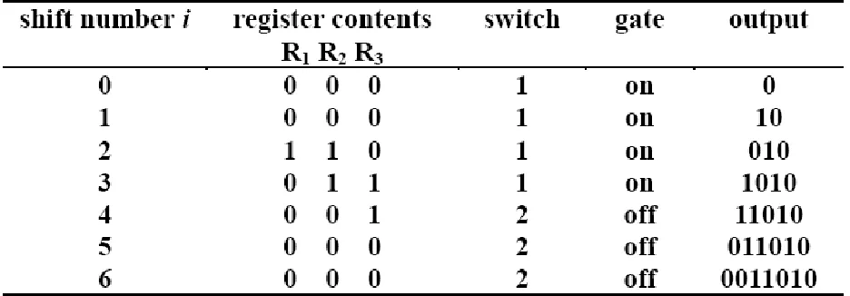
RCOE T.E(EXTC) SEMVI B-3 Page 2 Encoder for (7, 4) Cyclic Code Generator by g(x) =1+x2+x3
Table showing the register contents of encoder
The following describes the encoding procedure for encoder shown above:
1. Switch 1 is closed during the first k shifts, to allow transmission of the message into the n-k stage
encoding shift register.
2. Switch 2 is in the down position to allow transmission of the message bits directly to an output
register during the first k shifts.
3. After transmission of the kth message bit, switch 1 is opened and switch 2 is moved to the up
position.
4. The remaining n – k shifts clear the encoding register by moving the parity bits to the output
register.
5. The total number of shifts is equal to n, and the contents of the output register is the codeword
polynomial r(X) + xn-km(X). An (n,k) CRC code is capable of detecting all single bit errors and all
burst of adjacent bit errors with length less than or equal to the degree of the generator
RCOE T.E(EXTC) SEMVI B-3 Page 3 the polynomial division on the expanded bit stream and comparing the remainder with zero.
Some implementation Ex-ORs a fixed bit pattern into the remainder of the polynomial division. Some schemes view the low-order bit of each byte as "first". This convention makes sense when
serial-port transmissions are CRC-checked in hardware, because some widespread serial-port
transmission conventions transmit bytes least-significant bit first.
With multi-byte CRCs, there can be confusion over whether the byte transmitted first or stored in
the lowest-addressed byte of memory is the least-significant byte or the most-significant byte. For
example, some 16-bit CRC schemes swap the bytes of the CRC.
Since the high-order bit is always 1, and since an n-bit CRC must be defined by an (n + 1)-bit
divisor which overflows an n-bit register, assuming that it is unnecessary to mention the divisor's
RCOE T.E(EXTC) SEMVI B-3 Page 4 Connections for Cyclic Encoding and Decoding of BCD bit sequence
Procedure for Cyclic Encoding and Decoding of BCD bit sequence:
1. Connect the power supply mains cord to the ST2120, but do not turn ON the power supply until
connections are made for this experiment.
2. From Clock Section, connect 16 KHz Clock output to Clock Generator (Clock input).
3. Connect the Data Clock of clock generation section to Data Clock of Data Source.
4. Connect the Data Out of Data Source to Data In of Cyclic Encoder.
5. Connect the Code Clock of Clock Generation section to Code Clock of Cyclic Encoder.
RCOE T.E(EXTC) SEMVI B-3 Page 6 Data and Codeword
Observations for Cyclic Encoding and Decoding of BCD bit sequence:
1. The data output of Data Source is a repeating sequence of input data selected through BCD
switches.
2. The 8 bits of output data are binary coded decimal values on BCD switches.
3. The output data rate of Data Sources is selected through the input data clock.
4. Encoded and decoded data stream is same as observed on segmental display as well as waveforms
RCOE T.E(EXTC) SEMVI B-3 Page 7 Connections for Error Detection & Correction of bits sequence.
Procedure for Error Detection & Correction of bits sequence :
1. Connect the power supply mains cord to the ST2120, but do not turn ON the power supply until
connections are made for this experiment, and make all connections as in experiment 1.
2. Connect Code Word output of Cyclic Encoder to Code Word Input of Serial to Parallel convertor.
3. Connect output of Serial to Parallel convertor to input of Parallel to Serial Convertor.
4. Now transmit one of the bits of serial to parallel through Error insertion unit and observe that code
word of Parallel to Serial converter is different from that transmitted by Code Word generator, it
shows the presence of error in code word.
5. Connect the Code Word With Error terminal of Parallel to Serial Convertor to Received Code
Word terminal of Error Detection & Correction section,.
6. Connect Corrected Code Word terminal of Error Detection & Correction to Code Word terminal
RCOE T.E(EXTC) SEMVI B-3 Page 8 7. Connect the Data Out of Cyclic Decoder to Data In of display, which shows the received data
which is needed to be the same as transmitted by Data Source.
8. Repeat the above steps of experiment with different clock signal and observe the waveforms of
data and codeword.
Observation for Error Detection & Correction of bits sequence.
RCOE T.E(EXTC) SEMVI B-3 Page 9 Error Codeword and Corrected Codeword
Observations for Error Detection & Correction of bits sequence :
1. The received code word sequence pattern varies as we change the position of error bit in the
stream.
2. Encoded and decoded data stream is same as observed on segmental display as well as waveforms
on CRO.
CONCLUSION:
1. The data output of Data Sources on providing to Cyclic Encoder generate the code word by
inserting certain redundant bits to data bits.
2. The code word is appearing correctly with different data clock applied and the result is also
verified on oscilloscope.