©Shiraz University
A Comparison Between Numerical and Analytical Modeling of ECAP
M. Rejaeian and M. Aghaie-Khafri
*Faculty of Mechanical Engineering, K.N. Toosi University of Technology, Tehran, Iran. Abstract: Recent developments in nanostructured products draw considerable attention to ultrafine grained materials. These materials are normally manufactured by different severe plastic deformation (SPD) methods. In the present study, analytical models and finite element method (FEM) are used to calculate strain imposed to a specimen that was deformed by equal channel angular pressing (ECAP). In addition, strain inhomogeneity in term of coefficient of deviation (CV) for an aluminum alloy (AA6101) which was processed under ECAP was calculated. Dies with 90º, 105º and 120º intersecting angles were modeled based on FEM. Furthermore, the effect of friction on force-displacement curves was investigated using analytical and numerical approaches. Moreover, the energy loss that is due to friction was computed. Strains calculated by FEM for different die angles were identical to those evaluated by analytical models. Based on the numerical and analytical models, it has been shown that strain inhomogeneity increases when the angle between two channels decreases.
Keywords:ECAP, simulation, strain inhomogeneity, friction
1. Introduction
Since nanotechnology is regarded as an essential element for advanced industry fields, various methods such as powder metallurgy, thermo mechanical processing and severe plastic deformation (SPD) have been proposed in order to manufacture ultra-fine grained materials. SPD can be used to manufacture a full dense product whose strength is noticeably high. Equal channel angular pressing (ECAP) which was invented by Segal is known as a technique for imposing severe deformation on materials. It is possible to repeat this process for a number of passes to refine grain structure [1].
A comparison between numerical… 57
element modeling (FEM). Simulated load-stroke curve and peak load calculations were compared with the experimentally recorded load-stroke curve and peak load. A good conformity was observed between the FEM calculations and experimental results [7]. Basavaraj et al. carried out a 3D simulation of ECAP process for different channel angles for a strain hardening aluminum alloy [8].
However, in the present work, FEM was applied in order to predict strain, strain inhomogeneity and required loads during ECAP process. Results were compared with analytically obtained data. Process parameters are discussed based on the numerical and published analytical models.
2. Finite element analysis
A square cross section billet of 5mm5mm12mm was considered as starting material. Mechanical properties of aluminum alloy AA6101 [9] was assigned to the deformable work piece. Since dies are manufactured from high strength steel, both channels intersecting each other were modeled as rigid bodies. The inner and outer radiuses of the die were 0.01 m and 0.02 m, respectively. Dies with 90º, 105º and 120º intersecting angles (the angle at which two channels meet) were modeled. In order to reduce run time, only half section of the work piece was modeled.
Tangential behavior with various friction factors of 0.05, 0.1 and 0.15 were introduced as features of mechanical contact between specimen and tools. The amount of strain induced to an ECAPed billet was predicted based on Eq. (1) that is proposed by Iwahashi [10]:
2
2
cos
2
2
cot
2
3
nN
ec
(1)
where ψ is the outer radius angle and Φ is the intersecting angle. It is reported that Eq. (1) is a general form of other models presented in the literature [11].
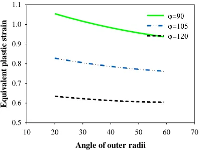
The coupled effect of ψ and Φ on the accumulated strain was plotted in Fig. 1, which is based on the Eq. (1). Despite the fact that there is a considerable increase in strain when Φ decreases, a reduction in ψ led to a slight rises of strain. The inhomogeneity index (Ci) as it is defined by Eq. (2) and the coefficient of variance of the equivalent plastic strain (CVεp, where subscript “εp” stands for the equivalent plastic strain) defined by Eq. (3) are frequently mentioned as the two main strain inhomogeneity indexes [8].
p p p i Avg Min Max C
(2) and, p p Avg stdev CV p
(3)
Where Max, Min, Avg and stdev are the maximum, the minimum, the average and the standard deviation of the equivalent plastic strain, respectively. The average of the strain is computed by Eq. (4):
n
Avg
n i i p p
1
(4)
Where n is the number of points at which strain has been measured. The strains in several points which located along a virtual path were calculated.
Angle of outer radii
10 20 30 40 50 60 70
Eq u iv al e n t p las ti c s tr ai n 0.5 0.6 0.7 0.8 0.9 1.0 1.1
Fig. 1. Plastic strain versus the angle of outer radii (
) for different intersecting angles (
).It should be pointed out that Eq. (3) is more accurate due to the fact that it takes all stain points into account, while Eq. (2) just considers two extreme values of strain. Perez and Luri‟s upper bound model, Eq. (5), is used in this study in order to obtain an approximate force that is required for conducting ECAP [6].
0F
DW
3
sin
2
2
0
initial int ext initial
1
m
w(2L
(
)(R
R )(1
)) D(2L
)
3
sin(
)
2
2
(5)
A comparison between numerical… 59
3. Results and Discussion 3-1 strain and strain inhomogeneity
Fig. (2) indicates strain inhomogeneity that is measured by the coefficient of variance of the equivalent plastic strain (CVεp).
Die angle
85 90 95 100 105 110 115 120 125
S
tr
a
in
i
n
h
o
m
o
g
e
n
e
it
y
(
C
V
)
0.24 0.26 0.28 0.30 0.32 0.34 0.36 0.38
Fig. 2. Strain inhomogeneity calculated based on CV for different die angles.
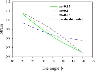
Some strain points were evaluated in a steady zone where deformation occurs in a constant rate. Then, average strain as well as strain inhomogeneity in term of the standard deviation of plastic strain was obtained. Fig. 3 shows that a die with
90
imposed severe strain to the sample.Die angle
85 90 95 100 105 110 115 120 125
S
tr
ai
n
0.6 0.7 0.8 0.9 1.0 1.1 1.2
m=0.15 m=0.1 m=0.05 Iwahashi model
Fig. 3. Analytically and numerically evaluated strains for different friction factors.
There is a considerable drop in strain and strain inhomogeneity when the angle between channels increases. It should be noted that other parameters such as outer and inner radius affect the deformation of the workpiece. Fig. 3 also indicates strain curves for different friction factors. It is clear that friction has a negligible effect on the induced strain.
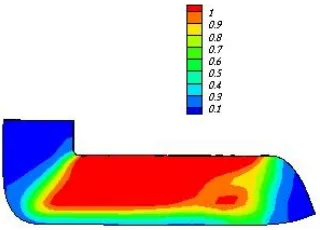
Fig. 4. Strain distribution profile for a) Φ=120º b) Φ=105º, c) Φ=90º, where Rext and Rint are 0.02 m and 0.01 m,
respectively.
Fig. 5 shows a die with external (Rext) and internal corners radius (Rint) of 0.015 m and 0.0006 m, respectively. As it can be observed, a die with sharper corners imposes more uniform strain on the deformable body and in this case the distribution of strain is more homogeneous when it is compared to a die which has a larger curvature (Fig. 4c). Thus, it is concluded that strain inhomogeneity reduces when the die corner radius decreases.
A comparison between numerical… 61
3-2 load-stroke curve
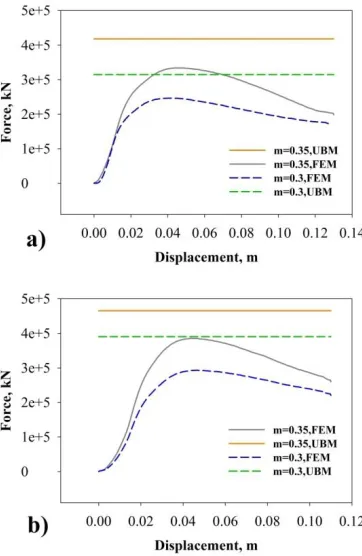
Load-stroke curves and required load for different friction conditions (0.3, 0.35) which were obtained via FEM and upper bound approach proposed by Perez and luri are discussed. Force-displacement curves for dies with 90º and 105º angles are shown in Fig. 6. It can be observed that there is a considerable
difference between the upper bound results and the FEM results. Results of the diversity of the finite element analysis and the upper bound analysis are discussed as following:
1. In the upper bound model, strain hardening is not considered and the yield stress or the average of the flow stress is used. Meanwhile, in the FEM (ABAQUS) analysis, the stress and force are calculated in each step via current yield point, which is updated based on the calculated strain.
2. The predicted load by the upper bound theorem is always greater than the real. It is well known that the upper bound theorem is founded on the kinematically admissible velocity fields (kavf). Among an infinite number of kavf, the one, which minimizes the total power, is recognized as the real velocity field. Perez and luri‟s upper bound model has been derived based on geometrical relations and no minimization has been done. If the minimization was carried out the model would predict more precise values for the pressing load.
3. A simple definition of contact surfaces and friction condition that is founded on the occurrence of the shear in the material is considered by the upper bound model. However, the properties of contact surfaces that is founded on the „mechanical contact theory‟ are more complex.
Considering Fig. 6, at the beginning of the process the force increases with a high rate. This is attributed to the work hardening phenomenon and the clearance between tool and material, which caused billet to be forged rather than ECAPed. When the gap was filled, material moved through exiting channel and non-uniform flow of the material was observed. Both the uniform deformation and the substitution of dynamic friction with static friction lead to a drop of load. As it can be observed, the load increases when the friction increases. This shows that friction mode has a noticeable effect on the force required for performing ECAP.
It must be pointed out that analytical and numerical approaches result in approximate solutions. However, they can be used to reduce the trial and error in the die design process. Furthermore, if the physical condition and process parameters are precisely taken into consideration, simulation results will be reliable.
4. Conclusion
ECAP of AA6101 aluminum alloy was investigated using the upper bound method and numerical approaches. The following conclusions can be drawn.
1. Measured strain by FEM for different die angles was almost close to those evaluated by analytical models.
2. Based on the numerical and analytical models, strain and strain inhomogeneity increase with the decreasing of the two channels interface angle.
3. In a die with low corners radii, the strain over the deformed workpiece was distributing more uniform.
4. The pressing loads are in good agreement for squeezing the billet through the channel that were assessed by simulation and analytical equations.
5. While force changes remarkably under different friction conditions, strain is not affected by the friction.
5. References
[1] K. Narooei, A. Karimi Taheri, A new model for prediction the strain field and extrusion pressure in ECAE process of circular cross section, Applied Mathematical Modelling, 34 (2010) 1901-1917.
[2] V. Segal, Slip line solutions, deformation mode and loading history during equal channel angular extrusion,
Materials Science and Engineering: A, 345 (2003) 36-46.
[3] M. Reihanian, R. Ebrahimi, M. Moshksar, Upper-bound analysis of equal channel angular extrusion using linear and rotational velocity fields, Materials & Design, 30 (2009) 28-34.
[4] B. Altan, G. Purcek, I. Miskioglu, An upper-bound analysis for equal-channel angular extrusion, Journal of
materials processing technology, 168 (2005) 137-146.
A comparison between numerical… 63
[7] A. Nagasekhar, S. Yoon, Y. Tick-Hon, H. Kim, An experimental verification of the finite element modelling of equal channel angular pressing, Computational Materials Science, 46 (2009) 347-351.
[8] V. Patil Basavaraj, U. Chakkingal, T. Prasanna Kumar, Study of channel angle influence on material flow and strain inhomogeneity in equal channel angular pressing using 3D finite element simulation, Journal of materials
processing technology, 209 (2009) 89-95.
[9] D. Nagarajan, 2005. Processing of an aluminium alloy by ECAE, p.t.c.e.M.S.T.I.I. of, p. Technology Madras. [10] Y. Iwahashi, J. Wang, Z. Horita, M. Nemoto, T.G. Langdon, Principle of equal-channel angular pressing for the processing of ultra-fine grained materials, Scripta Materialia, 35 (1996) 143-146.