Study on the Design of Soft Surgical Robots for
Endoscopic NOTES Applications
M.W. (Muhammad) Gifari
MSc Report
Committee: Prof.dr.ir. C.H. Slump Dr.ir. M. Abayazid H. Naghibi Beidokhti, MSc Dr. L. Masia
August 2018
031RAM2018
Robotics and Mechatronics
EE-Math-CS
University of Twente
P.O. Box 217
7500 AE Enschede
iii
Summary
With the advance of surgical operation from open surgery toward Minimally Invasive Surgery (MIS) and recently Natural Orifice Transluminal Endoscopic Surgery (NOTES) the surgeons are barely keeping up with the instrumentation. Endoscope that was originally a tool to examine the inside of patient body is now developed to perform surgical task. Advances have been made in the conventional endoscopic instruments, however several problems still arise.
The conventional endoscopic instruments can be categorized into two categories: rigid and flexible instrument. When the target organ is near incision point, such as in MIS, surgeons will place trocar and insert rigid endoscopes (can be several endoscopes at once) to perform the surgery. While this tool provide stability, it does not have flexibility. This rigid instrument is only effective when the target organ is directly in front of the incision point. When the target organ is deep inside patient body, or obscured by other organ, such as in gastrointestinal (GI) surgery, then flexible endoscope is the choice. Clearly this endoscope allows flexible navigation inside patient lumen. However, when a surgical intervention is performed, this flexible endoscope is not stable enough to perform the required operation.
Other problem of flexible endoscope is the trackability of the instrument inside the patient lumen. In case of rigid endoscope, trackability is not an issue because the instrument is not deeply inserted. In case of flexible endoscope, the view of endoscopic camera is usually narrow and currently the endoscope is not trackable inside the lumen. The endoscope may end up in wrong branch or arriving at incorrect operation target. Another limitation of flexible endoscope is the control method. Currently, the surgeons push the instrument manually inside patient body, and control is possible only at the tip of endoscope. This may cause the endoscope to form a loop inside patient body. In this case, further pushing of the endoscope is painful and the endoscopy is incomplete.
Our study aimed to design new surgical endoscope that can fulfill four important capabilities to tackle the problems mentioned: bendability, trackability, stiffness adjustability, and controllability. To attain the research aim, the idea is to design octopus-like soft robots actuated by pneumatic chambers. We improved previous pneumatic soft surgical robots (STIFF-FLOP) by increasing the number of chambers to four and merging stiffening and bending capability in each chamber. Benefits of having four chambers includes more intuitive control, antagonistic activation, and increase in resultant moment arm when activating two adjacent chambers. The embedding of stiffening sac into the chambers enable multi-level stiffness adjustment.
v
Acknowledgement
My biggest gratitude for God who has granted me courage, strength, and patience for this milestone in my life. Sincere thanks to my Prophet who introduced me to God and the beautiful way of life.
I thank my parent, my brother, and my wife for endless support until I can be where I am now.
I would like to thank Lembaga Pengelola Dana Pendidikan (LPDP) from Indonesian Ministry of Finance for supporting me with full scholarship. My study would not have been possible without their generous support.
My thanks also go to my supervisor, Momen Abayazid and Hamid Naghibi, for their support and guidance (and patience) that would make me possible to finish my master thesis.
Thanks for Lorenzo Masia and Prof Kees Slump for becoming my committee member.
Credit also goes to Jolanda for her support with all formalities, and the four technicians: Gerben, Sanders, Henni, and Marcel who has helped me greatly in the lab.
Thanks to Willem for the fruitful discussion about soft endoscope. Also, to Jorn who has developed the first control algorithm, and enable me to study greatly from his report. Thanks to Vincent for introducing me to the pneumatic components.
vii
Table of Contents
Summary... iii
Acknowledgement ... v
Table of Contents ... vii
List of Figures ... x
List of Tables ... xiii
1. Introduction... 1
1.1. Context ... 1
1.2. Limitation of Conventional Endoscope ... 1
1.3. Research Question... 2
1.4. Thesis Outline ... 2
2. Literature Review ... 5
2.1. Introduction ... 5
2.2. Method of Review ... 6
2.3. Soft Robotics: Nature Meets Engineering ... 6
2.3.1. Actuators ... 6
2.3.2. Stiffening in Soft Robots ... 8
2.3.3. Control ... 8
2.4. State-of-the-art Robotics Endoscopes ... 8
2.5. State-of-the-art Soft Robotics Endoscopes ... 9
2.5.1. MINIR ... 9
2.5.2. Meshworm ... 10
2.5.3. STIFF-FLOP ... 10
2.6. Design Summary and Gap... 11
2.7. Future Endoscope Design Concept & Specification ... 12
3. Mechanical Design of Multi-Level Stiffness Controllable (MOLLUSC) Endoscopic Module ... 15
3.1. Design platform: STIFF-FLOP ... 15
3.2. Improvements of STIFF-FLOP design ... 16
3.3. Design Overview... 18
3.4. Fabrication ... 20
3.4.1. Robot body fabrication ... 20
3.4.2. The Braided Sheath & Granular Jamming Membrane ... 21
3.4.3. Components assembly ... 21
4. Experimental Characterization of MOLLUSC Endoscopic Module ... 23
4.1. Aim of the Experiments ... 23
4.2. Experiment Setups ... 23
4.2.1. Maximum Pressure ... 23
4.2.2. One chamber bending... 23
4.2.3. Two chambers bending ... 24
4.2.4. Pressure versus Elongation ... 24
4.2.5. Pressure versus Force ... 24
4.2.6. Stiffening testing ... 24
4.3. Results... 24
4.3.1. Maximum Pressure ... 24
4.3.2. One Chamber Bending ... 26
4.3.3. Two Chambers Bending ... 26
4.3.4. Pressure versus Elongation ... 28
4.3.5. Pressure versus Force ... 28
4.3.6. Stiffening Testing ... 29
4.4. Discussion ... 30
4.4.1. Maximum Pressure ... 30
4.4.2. One Chamber Bending ... 30
4.4.3. Two Chambers Bending ... 31
4.4.4. Pressure versus Elongation ... 31
4.4.5. Pressure versus Force ... 32
4.4.6. Stiffening Testing ... 32
4.5. Conclusion of Experimental Characterization ... 32
5. Kinematic Position Control of MOLLUSC Manipulator ... 33
5.1. Robot mapping ... 33
5.1.1. Robot independent mapping ... 33
5.1.2. Robot specific mapping ... 34
5.2. 2D position control of the robot ... 35
5.3. Simplification and Assumption for 3D Control of the Robot ... 36
5.4. Implementation of the Control System ... 37
5.5. Validation: Static position control ... 38
5.6. Validation: Dynamic position control ... 40
5.7. Conclusion of kinematic control of the robot ... 42
ix
6.1. Conclusion ... 43
6.2. Future direction ... 43
References ... 45
Appendices ... 49
A. First Design Study – Antagonistic Pneu-net... 49
A.1. Design Overview... 49
A.2. Method of Manufacturing ... 50
A.3. Low-level Control System ... 51
A.4. Experimental Characterization: Bending testing ... 51
A.5. Discussion and shift to the next design ... 52
List of Figures
Figure 1.1 (left) rigid endoscope in operation[1]), (right) flexible endoscope in operation[2] ... 1 Figure 2.1 Common actuator for soft robots: (a) SMA actuator, (b) McKibben actuator, (c) FEA actuator, (d) Fiber-reinforced FEA [25] ... 7 Figure 2.2 (left) stretchable conductors to measure strain via measured current, (right) magnetic curvature sensor comprised of a miniature magnet and Hall effect sensor, embedded on a flexible circuit [13] ... 7 Figure 2.3 (left) tip of Invendoscoy E200 [23], (right) NeoGuide [23] ... 9 Figure 2.4 (a) Two configurations of tendon routing in continuum robot , (b) schematic of the forces acting in base disk when distal disk is bent according to cable routing of the 2nd configuration [21], (c) Meshworm robot [24] ... 10 Figure 2.5 (left) The first design of STIFF-FLOP manipulator, with semi cylindrical pneumatic chambers and external braided sheath [36] (middle) Improvements in the second design by using braided cylindrical pneumatic chambers [29], (right) 3rd design of STIFF-FLOP manipulator [3] ... 11
Figure 3.1 (left)The structure of STIFF-FLOP actuator, (right) bending of the STIFF-FLOP actuator without the external braided sheath [36] ... 15 Figure 3.2 (left) analysis of STIFF-FLOP design by Fras et al (2015), (1) depicted the non-actuated state, (2) depicted the actuated state. The resultant bending angle of simultaneous chamber activation is less than r1+r2 [35], (right) module design of third generation of STIFF-FLOP manipulator [3] ... 16 Figure 3.3 (left) cross-section center displacement in STIFF FLOP design, 1 depicts unactuated state, 2 depicts the actuated state, the resultant vector of two actuated chambers cross-section center is decreased [35], (right) the resultant cross-section center in our design is also decreased, but not as much as in [35] because the angle between chambers is 900 instead of 1200 so the net resultant vector is r2 instead of r .. 17
xi
Figure 3.9 manufactured MOLLUSC manipulator ... 22
Figure 3.10 control system to actuate one chamber of MOLLUSC actuator ... 22
Figure 4.1 (left) the failure at the bottom part of front chamber, (right) the bottom part of front chamber is torn ... 25
Figure 4.2 pressure versus bending angle characteristic for one chamber bending ... 26
Figure 4.3 pressure versus bending angle characteristic for two chambers bending ... 27
Figure 4.4 pressure versus bending angle characteristic for one and two chambers bending ... 27
Figure 4.5 pressure versus elongation graph for module with and without jamming ... 28
Figure 4.6 pressure versus force graph for module with jamming ... 29
Figure 4.7 Displacement versus applied force for stiffening testing of MOLLUSC manipulator in base condition, (inset) setup of the testing ... 29
Figure 4.8 Displacement versus applied force stiffening testing of MOLLUSC manipulator in bend condition ... 30
Figure 5.1 (left) constant curvature arc, the origin of curvature is located on (r,0), (right) arc parameter in constant curvature robot, 𝑙 is the robot backbone length, κ is the curvature of the robot, φ is out-of-plane rotation angle [39] ... 33
Figure 5.2 Kinematics model of constant curvature continuum robot according to Webster (2010) [39] 33 Figure 5.3 (left) schematic of three chambers robot depicting arc parameters of the robot and of chamber r1 (right) schematic of three chambers robot as seen from top, depicting also the arc parameters of the robot and of chamber r1 [39] ... 34
Figure 5.4 The fitting of pressure versus chamber length relationship for right bending of left bending of the module [47] ... 35
Figure 5.5 Algorithm of passive chamber compensation [47] ... 36
Figure 5.6 (left) Validation result of 2D bending angle control of MOLLUSC manipulator, (left) difference between setpoint and actual bending angle of left bending, (right) difference between setpoint and actual bending angle of right bending [47] ... 36
Figure 5.7 implementation of the control system on hardware level. The input signal of 𝜃 & ϕ is sent to Arduino and translated into pressure of the two regulators P1 and P2, and the ON/OFF configuration of the two solenoid valves to choose which chamber(s) to activate ... 38
Figure 5.9 algorithm to move the robot between two points. Input to this algorithm is the pair 𝜃, ϕ of the origin point 𝜃ori, ϕori 𝑎𝑛𝑑 𝑡ℎ𝑒 𝑒𝑛𝑑 𝑝𝑜𝑖𝑛𝑡 𝜃end, ϕend. First, the robot is moved to 𝜃ori, ϕori then the robot goes from 𝜃ori, ϕori to 𝜃ori, ϕend. Lastly, the algorithm will move the robot from 𝜃ori, ϕend to
𝜃end, ϕend ... 38 Figure 5.10 (left) determination of robot curvature, robot curvature is calculated by averaging the value of r1 and r2 (right) testing setup for 3D position control of the robot. Aurora tracker is placed in front of the robot... 39 Figure 5.11 Recorded robot position and cacluclated robot position at 𝜃=70 deg bending, as seen from above the X-Y plane. ... 40 Figure 5.12 robot trajectory compared to ideal trajectory for one quadrant movement as seen from above the X-Y plane. Direction of ϕ=0° is depicted by the black line ... 41 Figure 5.13 robot trajectory compared to ideal trajectory for full circle movement as seen from above the X-Y plane. Direction of ϕ=0° is depicted by the black line. X and Y are expressed in mm. ... 41 Figure 5.14 robot trajectory compared to ideal trajectory for full circle movement, (right) error in 𝜃 𝑎𝑛𝑑 𝜙
xiii
List of Tables
Table 2.1 Design Versus Specification for conventional and soft robotics endoscope solution ... 12
Table 3.1 Mechanical Design Characteristic of STIFF-FLOP 1st generation module [36] ... 15
Table 3.2-Use case scenario for MOLLUSC manipulator in base condition ( + denotes positive pressure, - denotes negative pressure, 0 denotes neutral ) ... 18
Table 3.2-Use case scenario for MOLLUSC manipulator in one chamber bending condition ( + denotes positive pressure, - denotes negative pressure, 0 denotes neutral ) ... 19
Table 3.3-Use case scenario for MOLLUSC manipulator in two chambers bending condition ( + denotes positive pressure, - denotes negative pressure, 0 denotes neutral ) ... 19
Table 3.4-Use case scenario for MOLLUSC manipulator in elongation condition ( + denotes positive pressure, - denotes negative pressure, 0 denotes neutral ) ... 19
Table 3.5-Use case scenario for MOLLUSC manipulator in three chambers bending condition ( + denotes positive pressure, - denotes negative pressure, 0 denotes neutral ) ... 20
Table 4.1- maximum pressure versus bending angle characteristic for module without granular jamming ... 25
Table 4.2- maximum pressure versus bending angle characteristic for module with granular jamming ... 25
1 CHAPTER 1. INTRODUCTION
1.
Introduction
1.1.
Context
With the recent trend in surgical operation field, surgeons have begun to move from open surgery to less-invasive and very recently non-less-invasive surgery. Open surgery is the very first established method of operation by incising the skin part outside of the organ to be intervened. Minimally invasive surgery is performed by introducing minimal incision in the nearest access point in patient body, and then place trocar that enables the instrument to get into the target organ (Figure 1.1). In this paradigm, surgeons operate the instruments from outside the patient body, unlike the open surgery in which the surgeons’ hand directly control the device inside the surgery opening. Non-invasive surgery makes use of body natural orifice such as vagina or mouth for the surgical instruments to be inserted. In the minimally invasive and non-invasive surgery an endoscope that can be controlled remotely is used to access the organ (Figure 1.1).
The endoscope concept is that the proximal end of the device is controlled through the other distant end. This transmitted control enables the surgeons to control the device from outside the patient body. The transmission medium between the proximal and distal end of the endoscope can be either a rigid rod (coined rigid endoscope) or a flexible tube (termed flexible endoscope). At the distal end of the endoscope, surgeons can place camera and surgical instruments. Sometimes several endoscopes are used simultaneously to simulate surgeons’ eye and two hands inside patient body.
Figure 1.1 (left) rigid endoscope in operation[1]), (right) flexible endoscope in operation[2]
1.2.
Limitation of Conventional Endoscope
cannot turn around to intervene the target organ [3]. Flexible endoscope, while allowing for better navigation inside the patient body, lacks the stability in doing the surgical intervention [4]. To make a precise incision, the stiffness of the distal end of the endoscope needs to be adjustable [5].
Another existing problem with endoscope is the localization of the endoscope inside the patient body [6]. In the usage of rigid endoscope, the localization is rather straightforward because the endoscope is not inserted deeply from the incision point. However, in using the flexible endoscope to trace a long lumen the view from the endoscope camera is not synchronized with how far the endoscope has gone inside the patient body. There is no way up to date to verify where the endoscope is inside the body. Moreover, the lack of depth perception and horizon stability make the localization of the endoscope even more challenging. Another major limitation is the lack of controllability of the endoscope [7]. Rigid endoscope is clearly very limited in controllability. With flexible endoscope, while the distal tip can be controlled quite flexibly, the rest of endoscope tube cannot. To move the rest of the endoscope body, the surgeons need to push the endoscope. This method may result in the advancement of the distal tip to the wrong branch because of the lack of control combined with the lack of localization.
Other limitations that come from the pushing advance method of the endoscope are incomplete and painful endoscopy [8]. Incomplete endoscopy means the endoscope cannot reach the intended target. This may happen when the endoscope cannot advance in a sharp turn of the lumen. With current flexible endoscope, the lack of stiffness control might hinder the endoscope from moving forward and it will just form loop without being able to reach its target. On the other hand, there is a risk of damaging organ when rather stiff endoscope is pushed forcefully through the lumen. There is a need for variable stiffness segments of endoscope to be able to trace various turns inside of the lumen to avoid loop formation, while still enabling the flexible mode of endoscope to avoid painful pushing to the patient.
1.3.
Research Question
To solve the endoscope design problems mentioned in the previous paragraphs, there are several key capabilities needed. First, for the endoscope to have flexible state and rigid state, the endoscope needs to have stiffness adjustment property. The endoscope also required to have trackability for the surgeons to localize the robot inside patient lumen. To tackle the maneuverability problem, the endoscope needs to have
bendability and controllability. While bendability means the ability of the robot to bend, the controllability means the ability of the robot’s segment to bend simultaneously in the predefined path/ angle calculated by a control system. Bendability and controllability, together with stiffness adjustment property are useful for preventing incomplete and painful endoscopy.
This study aims to develop the mechanical design, experimental characterization and control of single module soft surgical endoscope. We will focus on all four important aspects of surgical endoscope: stiffness adjustment, detectability, bendability, and controllability. This study will not cover the instrument dual arm design.
1.4.
Thesis Outline
3 CHAPTER 1. INTRODUCTION
conclude with design concepts and specifications for future soft surgical endoscope. Chapter III will describe the design and fabrication technique to fulfill the design requirements. Chapter IV includes the mechanical characterization of the developed module. In Chapter V high-level control system based on constant curvature kinematics will be developed and validated both in 2D and 3D. Finally, in Chapter VI
5 CHAPTER 2. LITERATURE REVIEW
2.
Literature Review
2.1.
Introduction
During a surgery, less incision will reduce patient trauma and recovery duration. Minimally Invasive Surgery (MIS) and Natural Orifice Transluminal Endoscopic Surgery (NOTES) are gradually replacing purely open surgery. One of the common applications of MIS or NOTES is endoscopy. The endoscope is originally a tool only to see the inside of patient lumen, but now it has developed into a tool for surgical intervention, especially with the increasing trend of MIS and NOTES.
The current interventional endoscopes are either rigid or flexible. The rigid endoscope is useful when the target organ is near incision point. Using rigid endoscope, the surgical operation can be performed with enough precision and force. When needed to reach distant organ, rigid endoscopes cannot circumvent a healthy organ. On the other hand, flexible endoscope is useful for reaching distant surgical target, and are already used in NOTES procedure such as colonoscopy. However, flexible endoscopes lack the stability required for distant surgical intervention [9]. Therefore, there is a need to introduce modern approaches to design the surgical endoscope.
Soft robotics, inspired by nature, is an emerging field in which flexible and compliant material is used to design and implement various robotic systems [10]. Soft robotics has several characteristics that may benefit its application in surgical robotics field. First, the robot bodies that is comprised from soft materials can comply with its surrounding environment, reducing potential of damaging tissue or organs. Second, the bendable characteristics of soft robots may provide the robotics endoscope the maneuverability to trace inside patient lumen [11]. Third, the soft robots may have the stiffness adjustable properties that enable the robotics endoscope the ability to stiffen intended part of its body [12]. Lastly, most of the soft materials used in soft robotics can be used inside MRI bore [13]. This can introduce an MR-compatible feature for endoscopes which can solve the endoscope localization problem.
Several articles have reviewed the medical robotics for MIS applications (e.g. [14]–[18]) most of which are outdated. Moreover, a few studies reviewed the recent developments in soft robotics actuators and sensors [19], [20]. Despite all the progress in implementation of soft robotics in medical robotics application in the last decade, a review on different concepts of the designs specifically developed for endoscopic applications is missing but can give a useful overview of the current state of the field. It can also provide an insight into the advantages and disadvantages of each mechanism for future developments.
2.2.
Method of Review
The key articles from soft robotics explain the knowledge of the field with specific highlight on the actuation, sensing, control, and stiffness adjustability of soft robots. A survey was performed to find the relevant articles on soft robotics Endoscopes, using“Soft Robotics for MIS and NOTES” and “Soft Robotics Endoscope” as keywords. The relevant articles on soft robot design that have been preliminary tested for surgical endoscopic applications were selected. Subsequently, three most pioneering soft robot designs were reviewed as: MINIR, Meshworm, and STIFF-FLOP. As comparison, conventional robotics solution for surgical endoscope, Invendoscopy and Neoguide, were also included. Moreover, the key cited articles in the references of these studies were also investigated.
2.3.
Soft Robotics: Nature Meets Engineering
To gain insight into the soft robotics technologies, the current actuation and sensing technology used in soft robotics will be reviewed. The review will be followed by brief look at the stiffening mechanism of soft robots. The challenge for the control of soft robots will be shortly examined.
2.3.1.
Actuators
This subsection will describe briefly some of the most common actuators used in soft robots [25].
Shape Memory Alloy: Shape Memory Alloy: The basic technology behind SMA is Nickel Titanium (NiTi) alloy wire that contracts under joule heating. Under cooling, the SMA reforms back to its initial shape [26]. The SMA wire can be used as agonist actuator to generate pulling force.
Cable actuators: The cable actuator derives its inspiration from tendon in human body. A motor is used to generate pulling force to the cables, which in turn move or pull rigid connecting plates between body segments to apply bending. Such approach is commonly used to control continuum robots.
Pneumatic Artificial Muscle (PAM): also known as McKibben actuator, this type of actuator is composed of inflatable elastic tube surrounded by a braided mesh. actuator contraction, elongation, and even stiffening can be achieved by changing the weave pattern and angle of the braided mesh. Typically, this kind of actuators works with driving pressure in the range of 0.34-0.68 MPa [27].
7 CHAPTER 2. LITERATURE REVIEW
Figure 2.1 Common actuator for soft robots: (a) SMA actuator, (b) McKibben actuator, (c) FEA actuator, (d) Fiber-reinforced FEA [25]
Sensing is required for feedback control of the actuators. Three main requirements for integration of soft sensors are stated in literature [13]. First, the sensor must be compliant, so it does not affect the shape or the properties of the soft robot. Second, the sensor must be durable enough to stretch for many cycles of motion. Third, the sensor should not damage soft parts of the robot. There are several types of soft sensing currently employed in soft robotics design.
Resistive and Capacitive Stretchable Sensing: The largest challenge of soft sensors is the lack of elastic material with low elastic modulus that remain conductive at high strain [13]. Alternative approaches are passive resistive and capacitive element manufactured by embedding additives resistive or capacitive element into the elastomer matrix (example see Figure 2.2 left). However, the additive may stiffen the elastomer, so there is a trade-off between conductivity and softness of the robot.
Magnetic Sensing: Miniature magnet that exhibits Hall Effect is embedded in robot elastomer matrix to sense the strain of the robot (Figure 2.2 right). Non-contact nature of magnetic measurement has benefits including small dynamic artifacts, less effect on the mechanical properties of the elastomer, and small hysteresis [29].
Optoelectronic Sensing: another recent solution is to fabricate and integrate waveguides into the body of the soft robots. The power loss of the signal increases with increasing strain, because of longer pathways travelled by the light. The amount of signal loss can be used to deduce the shape of the robot [30].
[image:21.612.155.458.69.234.2]2.3.2.
Stiffening in Soft Robots
Currently, there are two ways of adjusting the stiffness in soft robots: using active actuators that are arranged in antagonistic manner and using semi active actuators that can change their elastic properties.
The antagonistic method exploits the use of active actuators that produce opposite force/ torque direction to each other (active-active) or are coupled with passive structure (active-passive) [12]. In nature, muscle co-contraction is an example of active-active stiffness adjustment, while muscle contraction and spring-like tendon is an example of active-passive stiffness adjustment. In soft robotics, the active-active pairs can be achieved by pairing any of the soft actuator mentioned in section 2.3.1.
Semi-active actuators work by modulating passive mechanical properties of the material itself. Examples include stiffness controllable material such as granular jammed membrane which stiffness can vary when vacuum is applied. Another example is electrorheological material (ERM) and magnetorheological material (MRM) that changes their stiffness when subjected to an external electric or magnetic field.
2.3.3.
Control
Accurate position and motion control of soft robots remain an unsolved problem due to several high-level challenges. Soft sensors and actuators usually have non-linear dynamics, making model-based approaches difficult. Most soft materials have viscoelastic properties, which introduce hysteresis and subsequently large inaccuracies in open-loop control. Furthermore, integrated sensors are rare, complicating state estimation and feedback-control methods. Dynamics gets additionally complicated as fluidic soft actuators often exhibit slow response to pressure stimulus because of the delay caused by the time the fluid takes to fully enter the activated chamber [13].
2.4.
State-of-the-art Robotics Endoscopes
Attempts have been made to design endoscopes that provide the four needed capabilities as mentioned in Chapter 1. Among the design from state of the art conventional robotics are Invendoscopy (Invendo Medical GmbH, Germany) and Neoguide (NeoGuide Endoscopy System Inc, Los Gatos, CA) [23]. These two robots are reviewed because they possess unique design ideas that might help in designing future endoscopes.
Invendoscopy consist of reusable single handheld controller, processing unit, and single use colonoscope [31]. The colonoscope can be inserted until as deep as 170 cm. The tip is bendable up to 1800 in all direction
9 CHAPTER 2. LITERATURE REVIEW
Figure 2.3 (left) tip of Invendoscoy E200 [23], (right) NeoGuide [23]
Neoguide colonoscope consist of 16 equally sized electro-mechanically actuated modules to form a snake like structure which can trace the lumen using computerized mapping [32] (Figure 2.3 right). The Neoguide uses programmable over-tube that prevents loop formation, thus avoid painful and incomplete endoscopy [33]. The tip of Neoguide can be guided to all direction [32]. The localization problem is tackled by external position sensor that measures the robot depth. Neoguide also enables two modes: passive and active. In the passive mode, the endoscope is relatively stiff. Multiple level stiffness control and independent stiffness control of each segment is not reported. The Neoguide is already approval by FDA.
2.5.
State-of-the-art Soft Robotics Endoscopes
Adopting the beneficial properties of soft robots mentioned in section 2.3, soft robotics is slowly found its application in the design of surgical endoscopes. Among the research projects on this topic, we have Minimally Invasive Neurosurgical Intracranial Robot (MINIR), King’s College London (KCL) Meshworm and Stiffness Controllable Flexible and Learnable Manipulator for Surgical Operation (STIFF-FLOP) [4], [21], [24]. Those soft robotics endoscopes will be discussed in term of four capabilities crucial for future endoscopes: stiffness adjustment, bendability, controllability, and detectability.
2.5.1.
MINIR
MINIR robot is specially designed for endoscopy neurosurgery. The robotic design has three segments, with 60 mm total length and a diameter of 12.6 mm [21]. The robot has 3 mm diameter of free lumen that is used for electrocautery wires, and suction and irrigation tube. The robot has snake-like body composed of four disks interconnected by inner plastic springs. The outer part is covered by a long continuous outer spring. Each segment is activated by two pairs of tendons in an antagonistic manner which enable pitch and yaw motion. The tendons are actuated using SMA spring actuators. The robot material ensures its MR-compatibility [21].
MINIR uses central tendon routing mechanisms to actuate its body. In most of the existing robots with tendon driven mechanism, the cable routing is done in the peripheral part of the robot (see Figure 2.4 left, 1st configuration). This makes the movement of each segment coupled, as bending the distal end will give
[image:23.612.170.449.76.162.2]Figure 2.4 (a) Two configurations of tendon routing in continuum robot , (b) schematic of the forces acting in base disk when distal disk is bent according to cable routing of the 2nd configuration [21], (c) Meshworm robot [24]
2.5.2.
Meshworm
The Meshworm design, inspired by earth worm, is developed for colonoscopy application [24] (Figure 2.4c). This 50 cm lenght robot is composed of three segments made of soft plastic-silicone mesh composite. The outer diameter of the mesh is 31 mm when uncompressed and 35 mm when compressed [24]. Front and rear segments can bend about two axes, compress, and elongate. Each segment is actuated by tendon wound around pulleys which are mounted on DC motors. Locomotion is achieved by continuous anchoring, contracting, and un-anchoring of segments, like how earthworm crawls on the ground. Closed loop control is enabled by embedding Hall Effect sensor to indirectly calculate the length of each tendon. PID controller then will adjust the length of each tendon. The robot has free lumen, and in the prototype presented, an USB camera is mounted at the end tip.
2.5.3.
STIFF-FLOP
STIFF FLOP is a surgical manipulator inspired by octopus arm [34]. As mentioned in [4], the STIFF-FLOP has evolved in three designs. In the first design of STIFF-FLOP, pneumatic actuation is employed to achieve multi-directional bending and elongation, while granular jamming is applied to vary the stiffness. The manipulator bodies are constructed from flexible and soft silicone elastomer, which enable the squeezing of the robot [34]. The robot consists of three fluidic chambers equally spaced in radial arrangement embedded in an elastomeric cylinder. The cylinder is then enveloped by a crimped sheath to limit the radial expansion of the chamber when inflated. Outer diameter of the overall module is 32 mm [34]. The granular jamming chamber is made of latex membrane filled with coffee powder and inserted in an 8 mm channel in the center of the STIFF-FLOP module. Jamming is induced by applying vacuum to the chamber. The design pursued by STIFF-FLOP used modular approach. Each module has the same stiffening and bending capability, and the length required for specific surgical purpose will determine how many modules are needed.
[image:24.612.102.509.75.197.2]11 CHAPTER 2. LITERATURE REVIEW
chamber and cylindrical cross-section will allow more optimal elongation and limit the radial inflation[35]. Removal of external sheath eliminates the friction with internal silicone elastomer [35].
Figure 2.5 (left) The first design of STIFF-FLOP manipulator, with semi cylindrical pneumatic chambers and external braided sheath [36] (middle) Improvements in the second design by using braided cylindrical pneumatic chambers [29], (right) 3rd design
of STIFF-FLOP manipulator [3]
The third design improves the second one by focusing on size reduction by excluding the central granular jamming membrane. The removal of this membrane opens space for free lumen inside the manipulator. Other improvement is the shift from one pneumatic chamber into a pair of pneumatic chambers. A pair of pneumatic chamber will make the resultant moment arm farther than single chamber, thus increasing the bending moment and stability [3]. Overall diameter of this third-generation design is 14.5 mm which fits into trocar for MIS operation. The two-module design had been implemented and tested in human cadaver and proved the reaching and bending ability of the manipulator [3].
2.6.
Design Summary and Gap
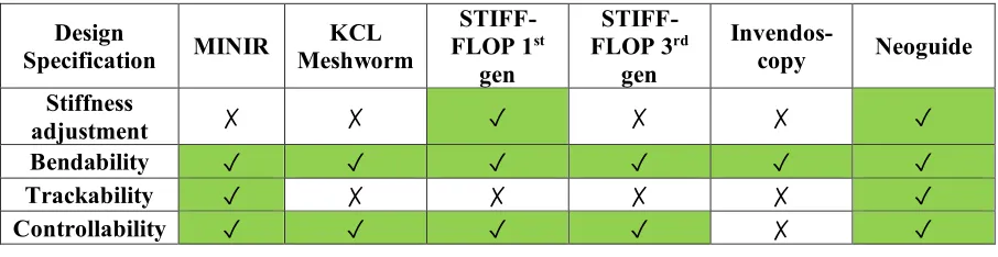
Summary of the designs reviewed against the four crucial capabilities in designing endoscope can be seen in table 1.
Stiffness adjustment in the Neoguide and STIFF-FLOP robot are achieved by semi-active actuators (refer to section 2.3.C). In STIFF-FLOP, the granular jamming membrane is used. However, in the 1st design of
STIFF-FLOP, the granular jamming membrane uses the central channel space which should have been used to house surgical instruments. The central lumen is emptied in the 3rd design of STIFF-FLOP at the cost of
removing the central granular jamming mechanism.
[image:25.612.71.524.121.219.2]Table 2.1 Design Versus Specification for conventional and soft robotics endoscope solution
Design
Specification MINIR
KCL Meshworm
STIFF-FLOP 1st
gen
STIFF-FLOP 3rd
gen
Invendos-copy Neoguide Stiffness
adjustment ✗ ✗ ✓ ✗ ✗ ✓
Bendability ✓ ✓ ✓ ✓ ✓ ✓
Trackability ✓ ✗ ✗ ✗ ✗ ✓
Controllability ✓ ✓ ✓ ✓ ✗ ✓
2.7.
Future Endoscope Design Concept & Specification
After reviewing the state-of-the-art design, we would like to propose new concept for doing the endoscopic operation, which is by doing remote endoscopic operation under MR guidance [21],[37]. To tackle the endoscope localization problem, the endoscope will be placed inside an MR bore. The use of soft robotics will enable robot that is made from fully MR-compliant material, and by using pneumatic actuation, the pneumatic pipe can be elongated so the patient can be fully inside the MR-bore, while surgeons control the device in the vicinity.
The future development of soft robots in endoscopic application should covers the mechanical design of the robot. From controllability standpoint, bendable modular continuum robot already has both forward and inverse kinematic model [38], [39]. Because using sensing modality will interfere with the MR-compatibility of the robot, for our new surgical concept, open-loop control using kinematic model is preferable. The open loop control using constant curvature model has been tested in [3]. Instead of pushing the endoscope to make its way inside the lumen toward target organ, now it is possible to bend some segments of the robot to avoid painful endoscopy. The most advanced control possible using the kinematic model of modular continuum robot is the path planning algorithm toward the target like the one implemented in Neoguide [32].
Another consideration in endoscope design is the stiffness adjustability of the robot. It is preferable that the robot has several stiffness levels. This will be useful for different purpose, for example the most distal tip will be very stiff for making the surgical incision, the module before the most distal tip will become slightly less stiff to support the distal tip, while some other module far at the back will be stiff to support the bending of the robot while tracing the curve inside the lumen.
The modular design in all soft surgical robots reviewed is a promising approach in building continuum robots. The modular design facilitates the manufacturing process in blocks. Other benefit includes the flexibility to adjust the length of the robot as necessary for specific application. From the design point of view, first one module proof-of-concept design should be realized and tested, before moving to multi-module design.
Based on the new surgical concept we proposed, and considering the mechanical aspects of the design, the future soft surgical endoscope for NOTES application should fulfil the following specifications:
• Safe especially from pressure leakage
• Fully biocompatible and MR compatible material
• Bending in at least two antagonistic direction
13 CHAPTER 2. LITERATURE REVIEW
• Modularity
• Adjustable stiffness in at least two levels
• Internal free central channel to house surgical tools such as endoscopic camera
15 CHAPTER 3. MECHANICAL DESIGN OF MOLLUSC ENDOSCOPIC MODULE
3.
Mechanical Design of Multi-Level Stiffness Controllable
(MOLLUSC) Endoscopic Module
3.1.
Design platform: STIFF-FLOP
1This design is based on the STIFF-FLOP manipulator introduced in previous chapter. The STIFF-FLOP uses three radially arranged expandable chambers to achieve its bending and one granular jammed central channel to achieve its stiffening. The chambers are expanded pneumatically. Design of 1st generation
STIFF-FLOP module can be seen in Figure 3.1. Under the activation of one bending chamber, the actuator will bend to the opposite direction (Figure 3.1). Under the activation of two chambers, the actuator will bend to the direction opposite to the central line between the two activated chambers. Actuating the three chambers together will elongate the manipulator. Experimental characterization of the STIFF-FLOP design is presented in Table 3.1.
[image:29.612.139.482.288.377.2]Figure 3.1 (left)The structure of STIFF-FLOP actuator, (right) bending of the STIFF-FLOP actuator without the external braided sheath [36]
Table 3.1 Mechanical Design Characteristic of STIFF-FLOP 1st generation module [36]
Characteristic Pressure condition Value
Maximum one chamber bending angle 0.65 bar 120°
Maximum two chambers bending angle 0.65 bar 80°
Maximum elongation 0.65 bar 86.3%
Maximum force at one chamber bending 0.65 bar 24.6 N
Maximum force at elongation 0.65 bar 41.4 N
Maximum stiffness variation Base condition (no pressure) 36%
One counter-intuitive characteristic is that pressurizing two chambers simultaneously reduces the bending angle than pressurizing one chamber. The reduction at 0.65 bar can reach value of 40° (Table 3.1). In STIFF-FLOP design, all chambers are separated by 1200. Denoting cross-section of one chamber as r,
activating two chambers together should make the resultant moment arm to be r. Therefore, activating two chambers simultaneously ideally should keep the same resulting bending angle. Moreover, analysis from STIFF-FLOP design mentioned chamber cross-section center displacement toward the center of the module, causes further reducing the resultant moment arm [35]. This resulted in less bending from two chambers bending in STIFF-FLOP [36] .
1 This is the second design that we tried. The first design has issue with the tubular bending of the actuator. Detail of
Figure 3.2 (left) analysis of STIFF-FLOP design by Fras et al (2015), (1) depicted the non-actuated state, (2) depicted the actuated state. The resultant bending angle of simultaneous chamber activation is less than r1+r2 [35], (right) module design of third generation of STIFF-FLOP manipulator [3]
In the third-generation design of STIFF-FLOP, the development was more focused toward MIS application and the target was to decrease the size of the module. Moreover, with the specific aim to use the STIFF-FLOP with a camera, the stiffening chamber was no longer implemented (Figure 3.2). There is positive aspect of the third design such as more efficient bending using a connected paired chamber. However, with the elimination of stiffening mechanism, the design is no longer fulfilling the need for stiffness controllable surgical tools for MIS and NOTES application.
3.2.
Improvements of STIFF-FLOP design
As discussed previously, STIFF-FLOP has stiffness adjustment ability with the drawback of not having the free central lumen. The third design has central free lumen with the drawback of eliminating the stiffness adjustment ability. In the current study, we build a new design based on STIFF-FLOP concept to achieve both free central lumen and stiffening as well as bending capabilities.
The first novel design concept that we propose in this work is the combination of granular jamming and actuation in one chamber. This combination of function will optimize the space inside the module. In our design, we achieve this by inserting the granular jamming sac inside the actuation chamber. By using solenoid valve, we can switch the input to the chamber either by vacuum line (for granular jamming) or by pressure line (actuation).
The second improvements made by our concept is that multi-level stiffening can be gained. First, we achieve this by controlling the vacuum level of the chamber. The second way of controlling the stiffness can be by activating one or several chambers. As the stiffening component was moved from central chamber to the side chambers, now different combination of chambers can be used which enables multi-level of stiffening: one chamber, two chambers, three chambers, and four chambers stiffening.
17 CHAPTER 3. MECHANICAL DESIGN OF MOLLUSC ENDOSCOPIC MODULE
(like muscle co-contraction). This modulation will enable more precise force exertion and better control [40].
Four chambers design hypothetically exhibit an increase in the moment arm in case of two chambers activation (Figure 3.3). In the case of three chambers design, the angular distance between chambers is 120°. Simultaneous activation of two adjacent chambers will result in moment arm of r. In case of four chambers design, the angular distance between chambers is 900. Therefore, activating two adjacent
chambers will result in moment arm of 𝑟√2. Although the chamber cross-section center of our design will also displaced toward the center [35], we expect resultant moment arm to be longer than STIFF-FLOP.
Figure 3.3 (left) cross-section center displacement in STIFF FLOP design, 1 depicts unactuated state, 2 depicts the actuated state, the resultant vector of two actuated chambers cross-section center is decreased [35], (right) the resultant cross-section center in our design is also decreased, but not as much as in [35] because the angle between chambers is 900 instead of 1200 so the net
resultant vector is r√2 instead of r
Figure 3.4 (left) compressive stress versus strain verified that coffee is the most suitable material for granular jamming grains
[41], (right) bending stiffness comparison of several granular jamming membrane under vacuum pressure [42]
The last modification is the jamming membrane. For the material of granular jamming sac, latex rubber and neoprene were compared. Qualitatively, latex resulted in lower stiffness than neoprene when vaccuumed. In previous research, it is found that latex is not the most ideal granular jamming membrane, and the polythene rubber outperforms latex for vacuum stiffness in bending, tension, and compression testing [42] (Figure 3.4). Considering the above finding, unlikr STIFF-FLOP we used neoprene for capsulatinf the jamming material.
3.3.
Design Overview
In short, first novelty of our design with respect to STIFF-FLOP is freeing the central lumen by moving the stiffening mechanism to every chamber. The chamber now can be used for both bending and stiffening. In addition, vacuuming the chamber individually will enable multi stiffness level. Other novelty is arranging the chambers in two antagonistic pairs, which will allow more intuitive control of bending and an increase in resultant bending angle. The use case scenario of our manipulator, which exploits multi-level stiffness capabilities, can be seen in Table 3.2 – Table 3.6. Drawing of the design can be referred to Figure 3.5.
Figure 3.5 design of the proposed MOLLUSC (Multi LeveL Stiffness Controllable) manipulator (left) top view of the mold, (right) side view of the mold
In the following, the new design is named MOLLUSC (Multi-LeveL Stiffness Controllable) robot. The biological inspiration of stiffness adjustable manipulator comes from octopus, and octopus fall under the taxonomy of mollusk. Hence, we give the name MOLLUSC aiming that the robot will mimic the ability of octopus arm.
Table 3.2-Use case scenario for MOLLUSC manipulator in base condition ( + denotes positive pressure, - denotes negative pressure, 0 denotes neutral )
Use Case
Number Scenario
Chamber 1 (right)
Chamber 2 (front)
Chamber 3 (left)
Chamber 4 (back)
1 Base condition 0 0 0 0
1a stiffness level 1 Base condition 0 0 0 -
1b Base condition
19 CHAPTER 3. MECHANICAL DESIGN OF MOLLUSC ENDOSCOPIC MODULE
Use Case Number
Scenario Chamber 1 (right) Chamber 2 (front) Chamber 3 (left) Chamber 4 (back)
1c Base condition
stiffness level 3 0 - - -
1d Base condition
stiffness level 4 - - - -
Table 3.3-Use case scenario for MOLLUSC manipulator in one chamber bending condition ( + denotes positive pressure, - denotes negative pressure, 0 denotes neutral )
Use case
Number Scenario
Chamber 1 (right) Chamber 2 (front) Chamber 3 (left) Chamber 4 (back)
2 Left bending + 0 0 0
2a Left bending Stiffness Level 1 + 0 - 0
2b Left bending stiffness level 2 + - 0 -
2c Left bending stiffness
level 3 + - - -
2d
Left bending stiffness level 4 (release the air
that causes left bending, and stiffen
that chamber)
- - - -
Table 3.4-Use case scenario for MOLLUSC manipulator in two chambers bending condition ( + denotes positive pressure, - denotes negative pressure, 0 denotes neutral )
Use case
number Scenario
Chamber 1 (right) Chamber 2 (front) Chamber 3 (left) Chamber 4 (back)
3 Back left bending + + 0 0
[image:33.612.73.530.447.519.2]3a Back left bending and stiffening + + - -
Table 3.5-Use case scenario for MOLLUSC manipulator in elongation condition ( + denotes positive pressure, - denotes negative pressure, 0 denotes neutral )
Use Case
Number Scenario
Chamber 1 (right) Chamber 2 (front) Chamber 3 (left) Chamber 4 (back)
4 Elongation level 1 + 0 + 0
4a Elongation level 2 + + + +
Table 3.6-Use case scenario for MOLLUSC manipulator in three chambers bending condition ( + denotes positive pressure, - denotes negative pressure, 0 denotes neutral )
Use case
number Scenario
Chamber 1 (right) Chamber 2 (front) Chamber 3 (left) Chamber 4 (back)
5 Left bending three chambers + + 0 +
5a
Left bending three chambers and
stiffening
+ + - +
3.4.
Fabrication
In this section the material and molds required for fabricating a single module robot will be discussed. Next, the manufacture of each part of the robots is described. Finally, the assembly and integration of the soft robot will be explained. The complete list of materials is listed in Appendix B.
3.4.1.
Robot body fabrication
To Fabricate the robot body, first we printed the mold using 3D printer (Objet260 Connex3, StrataSys Inc), in Verowhite and Veroclear material (Vero material, StrataSys Inc). Vero material is chosen not to make the mold sticky after its curing. In the previous design (the antagonistic pneunet – see appendix A) a PLA mold was tried out, and the material sticks very hard to the mold, making the removal of the cured elastomer difficult. Moreover, spraying at the molds using release agent will make the removal process of cured material easier.
Figure 3.6 mold of MOLLUSC manipulator, from left to right: cap_A, chamber, shell and central cylinder, cap_B
To process the silicone elastomer, first part A and part B of Ecoflex silicone (Ecoflex, Smooth on Inc) were mixed with 1:1 weight ratio. After that, the mixed material is vacuumed (-0.9 bar) for about 5 minutes to remove the air bubbles. After making sure that there is no bubble, we proceed to slowly pour the material into the molds.
21 CHAPTER 3. MECHANICAL DESIGN OF MOLLUSC ENDOSCOPIC MODULE
Figure 3.7 molding process of MOLLUSC manipulator, (a, b) the first part of molding, (c-f) the second part of molding [43]
3.4.2.
The Braided Sheath & Granular Jamming Membrane
To arrange the robot sheath, braided sleeve with minimum diameter of 10 mm and maximum diameter of 25 mm (RS 408-249, RS Components) was inserted into a 30 mm dimeter cylinder. The sleeve was then pushed down until crimped structure was formed. The structure was heated with a heat gun until the crimps was hardened with care for not melting the sleeve.
For the granular jamming membrane, first we cut the neoprene from neoprene gloves one half section of the little finger. This glove is filled with one gram of coffee powder. For the tube, first we cut cone section of the tea bag filter and wrapped it around the tube using thread and parafilm. Finally, the capped tube was inserted into the granular jamming sac and further wrapped using parafilm. The complete granular jamming sac can be seen in Figure 3.8 c.
(a) (b) (c)
Figure 3.8 (a) the cable sleeve for robot sheath, (b) the crimps are formed around the cylinder and heated [44] (c) a granular jamming sac
3.4.3.
Components assembly
Figure 3.9 manufactured MOLLUSC manipulator
3.5.
Low-Level Control System
A low-level control system for the MOLLUSC was developed as demonstrated schematically in Figure 3.10 to perform the charecterization experiment. Each chamber can be connected to a pressure line for actuation or vacuum line for stiffening using a switching valve. The pressure and vacuum can be adjusted using digital regulators. The pressure/ vacuum from digital regulator is first fetch into on/off solenoid valve. A switching solenoid valve in front of the two on/off valves will choose between delivering pressure/ vacuum to one chamber of actuator. In current implementation, for on/off valve, we used simple mechanical on/off valve, and for the switching valve, we used MHE series solenoid valve from Festo Inc. For the digital pressure regulator and vacuum regulator, we used positive and vacuum VEAB pressure regulator from Festo Inc respectively. With this configuration, working pressure from -1 to 1 bar is fetched to the actuator. This control system will ensure any of the chamber in either pressurized state, normal state, or vacuum state simultaneously to fetch all combination of state in the use case scenario mentioned in section 3.3.
23 CHAPTER 4. EXPERIMENTAL CHARACTERIZATION OF MOLLUSC ENDOSCOPIC
MODULE
4.
Experimental Characterization of MOLLUSC Endoscopic
Module
After developing the MOLLUSC, the module needs to be characterized in terms of bending, elongation, stiffening, and the exerted force. We examined the effect of adding granular jamming to the bending and elongation of the robot. The other testing includes observing the force exerted by the module and the stiffening capabilities. Some of the results will be compared with the previously developed STIFF-FLOP.
4.1.
Aim of the Experiments
In details, there are 6 characteristics that are observed: 1) maximum pressure, 2) pressure versus bending one chamber, 3) pressure versus bending two chambers, 4) pressure versus elongation, 5) pressure versus force, and 6) stiffness characteristics. Maximum pressure testing aims to determine the safe pressure that can be applied to the chamber to avoid chambers explosion. Pressure versus bending testing aims to answer the research question of achieving bendable soft endoscope. We will also examine the effect of pressurizing one chamber and two chambers simultaneously with the same amount of pressure. Pressure versus elongation will see how much the robot will elongate under simultaneous pressure. This elongation can add to the active robot degree-of-freedom and may enable more dexterous maneuvering of the robot. Force testing will check how much force the robot can apply and see whether it fulfills the specification mentioned in section 2.7. Finally, the stiffness testing aims to verify and quantify the stiffness adjustability of the robot in base condition and one chamber bending use case scenario (see Table 3.2 & Table 3.3).
4.2.
Experiment Setups
This section will explain the setup for each of the testing mentioned above. In general, the pressure was supplied using manual regulator and read by digital manometer.
4.2.1.
Maximum Pressure
The testing setup is as follow. One of the chambers was connected to the pressure regulator. Then, the pressure was increased in 0.05 bar step until either: 1) the chamber exploded, 2) the robot achieved 180° bending, or 3) the pressure regulator achieved its maximum pressure of 1 bar. By achieving a bending angle of 180°, the robot can already have almost fully spherical field of view, therefore there is no need to increase the bending (and pressure) any further. This test was conducted on the MOLLUSC version without and with the granular jamming material.
4.2.2.
One chamber bending
4.2.3.
Two chambers bending
In two chambers testing, the pressure is supplied to two adjacent chambers simultaneously. The range and step of supplied pressure is the same as one chamber bending testing. The resulting bending angle is captured by camera and measured in imageJ software. In taking the picture, the camera shot is perpendicular to the direction of bending. This test was conducted on all four possible combinations of adjacent chambers. Each chamber combination testing was repeated five times.
4.2.4.
Pressure versus Elongation
For elongation testing, two opposite chambers and all chambers are pressurized simultaneously. The strain or elongation is defined as the length difference of the module at any given pressure with initial length at pressure of 0 bar, defined in the percentage of initial length. The test was done two times for module with granular jamming, and one time in module without the granular jamming. In the 2nd testing with granular
jamming module, the bottom part of the chamber was slightly torn, therefore it was only possible to pressurize the module pressure up to 0.6 bar.
4.2.5.
Pressure versus Force
For measuring the force, we performed vertical force testing. This experiment was performed by placing an ATI mini 45 load cell on top of the robot, and then pressurizing the robot up to 0.75 bar with step of 0.05 bar. The vertical movement of the robot is constrained by the sensor; therefore, the vertical force is exerted on the sensor. The vertical force testing is done for two chambers elongation and four chambers elongation.
4.2.6.
Stiffening testing
For stiffening testing, ATI mini 45 load cell was mounted in a slider and the slider was held by laboratory clamp (Figure 4.7 inset). The slider was then placed just to touch the actuator from lateral slide. We then imposed displacement from 1 mm to 15 mm with a step of 1 mm, using the slider. The reaction force of MOLLUSC manipulator was recorded in each data point. We recorded the force in line to the direction of displacement. The stiffening experiments were performed for the robot in base condition and in one chamber bending condition with various stiffening level (use case scenario in Table 3.2 & Table 3.3). The pressure fetch to bend the manipulator was set to be 0.65 bar.
4.3.
Results
4.3.1.
Maximum Pressure
25 CHAPTER 4. EXPERIMENTAL CHARACTERIZATION OF MOLLUSC ENDOSCOPIC
MODULE
[image:39.612.69.529.436.645.2]Three of four possible chambers combination could achieve bending of almost 180°. The only exception was back right bending, which is comprised of two rather defect chambers, which resulted in less achievable bending angle.
Table 4.1- maximum pressure versus bending angle characteristic for module without granular jamming
Chamber Maximum
pressure (bar)
Reason of stopping at maximum pressure
Bending angle at maximum pressure (°)
Right 0.8 The chamber leaked very badly 129.5
Left 0.8 Almost 180° bending 177.3
Back 0.8 Almost 180° bending 173.2
Front 0.8 The chamber leaked very badly 128.3
Right + front 0.8 The chamber leaked very badly 111.5
Right + back 0.8 Almost 180° bending 166.2
Left + front 0.8 Almost 180° bending 168.9
Left + back 0.8 Almost 180° bending 171.8
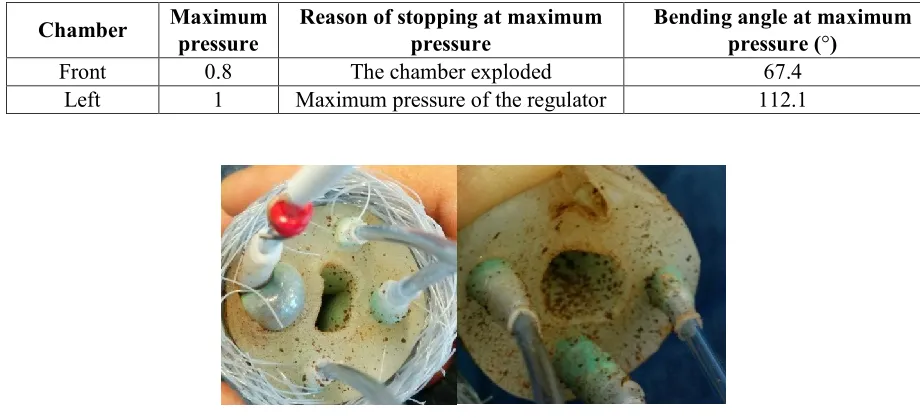
For module with granular jamming, one chamber exploded at pressure above 0.8 bar (Table 4.2). The other chamber (left) could withstand pressure until 1 bar, which is the maximum pressure the pressure regulator can deliver (Table 4.2). Although left chamber did not explode, the granular jamming sac started to push the chamber through the bottom side. Examining the chamber failure (Figure 4.1), we observed that front chamber failed by explosion of coffee powder at the bottom part of the chamber. This pressure from granular jamming sac also tear the bottom part of the module (Figure 4.1).
Table 4.2- maximum pressure versuss bending angle characteristic for module with granular jamming
Chamber Maximum pressure
Reason of stopping at maximum pressure
Bending angle at maximum pressure (°)
Front 0.8 The chamber exploded 67.4
Left 1 Maximum pressure of the regulator 112.1
4.3.2.
One Chamber Bending
The results of the bending experiment were presented in Figure 4.2. Each graph can be divided into three zones. One zone is zero bending angle, then the gradient started to appear with low value, and after some value of pressure the gradient suddenly rises.
[image:40.612.95.530.252.487.2]First difference between the module with and without the jamming material can be seen in the starting point of module response to pressure. The starting point of module without jamming is 0.15, while with jamming material it became 0.3 bar. The second difference is the achievable bending angle. Without jamming material, with a pressure of only 0.45 bar, the module can bend to 90°, While with jamming material, with 0.7 bar pressure, the bending is only 50° in average.
Figure 4.2 pressure versus bending angle characteristic for one chamber bending
4.3.3.
Two Chambers Bending
27 CHAPTER 4. EXPERIMENTAL CHARACTERIZATION OF MOLLUSC ENDOSCOPIC
[image:41.612.81.531.74.318.2]MODULE
Figure 4.3 pressure versus bending angle characteristic for two chambers bending
[image:41.612.90.530.436.673.2]Figure 4.4 summarizes the difference between the pressure versus bending effect on one and two chambers. With jamming material, the maximum achievable bending angle is less than without jamming material. Both bendings (one chamber and two chambers) showed similar behaviour with granular jamming material, whereas without jamming material, the one chamber bending showed slightly larger bending of about 10°.
4.3.4.
Pressure versus Elongation
Figure 4.5 illustrates the results of the elongation experiments. In STIFF-FLOP first design, it is reported that maximum elongation achieved at 0.65 bar is 86.3% [36]. In our design, the maximum achievable elongation in module without jamming is 43%, around half of the STIFF-FLOP module. In the module with jamming, the highest elongation achieved is 70%.
Figure 4.5 pressure versus elongation graph for module with and without jamming
4.3.5.
Pressure versus Force
From Figure 4.6 pressurizing four chamber always give more force than pressurizing two chambers. The maximum force of the module at 0.75 bar with two chambers elongation is 11.47 N. With four chambers elongation, the maximum force increases to 18.88 N. This corresponds to an increase of 65% in the applied force (Table 4.3).
[image:42.612.90.536.179.422.2]
Table 4.3-force delivered at various numbers of activated chamber
Condition maximum force @0.75 bar
(N) % increase from two elongation force
two chambers
elongation 11.47 0
four chambers
29 CHAPTER 4. EXPERIMENTAL CHARACTERIZATION OF MOLLUSC ENDOSCOPIC
[image:43.612.111.506.71.290.2]MODULE
Figure 4.6 pressure versus force graph for module with jamming
4.3.6.
Stiffening Testing
Results of stiffening testing in base condition can be seen in Figure 4.7. For level 2 stiffening, the stiffness increase was observed to be in the region of displacement after 10 mm. In level 2 stiffening, the two stiffened chambers were the chambers in the direction of applied force. For level 4 stiffening, the stiffening effect was observable in almost all displacement.
[image:43.612.90.532.433.675.2]Results of stiffening experiments in bend condition can be seen in Figure 4.8. For level 1 stiffening, the vacuumed chamber was the one opposite to the chamber activated for bending. In level 2 stiffening, the two stiffened chambers were the chambers in the direction perpendicular to applied force. For level 4 stiffening, the pressurized chamber was quickly switched to vacuum by valve.
Figure 4.8 Displacement versus applied force stiffening testing of MOLLUSC manipulator in bend condition
4.4.
Discussion
4.4.1.
Maximum Pressure
The coagulation of coffee powder at the bottom of the chamber can be explained as follow: The air pressure pushes the coffee powder inside the sac to all direction. The pressurized coffee powder may flock at the bottom of the sac due to the gravity. This pressure from the inside of the chamber is countered by relatively stiff material of Ecoflex 50. This pressure from two sides stiffen the coffee powder. When the pressure from inside is bigger than material strength of Ecoflex, then this stiffened coffee powder would slip (and sometime tear) the hole at the bottom of the chamber. To overcome this problem, one solution is to mold another material after the granular jamming sac is inserted. However, with this method, if something happens to the chamber, repairing the chamber is not feasible.
4.4.2.
One Chamber Bending
31 CHAPTER 4. EXPERIMENTAL CHARACTERIZATION OF MOLLUSC ENDOSCOPIC
MODULE
expansion of the chamber in any direction. The sudden increase in gradient (third curve zone) is due to the friction of chamber with the braided sheath, so the module now is bent into one specific direction [36]. The higher starting pressure of bending in module with jamming is caused by stiffer overall structure due to the neoprene sac and the coffee powder. This stiffer structure also causes the granular jammed module to achieve less bending angle at the same pressure than module without granular jamming. The coffee powder is stiffened at the bottom part of the chamber with the increasing pressure (see Figure 4.1). This stiffened chamber further restricts the chamber bending.
As discussed before, all the curves in bending versus pressure characterization have three zones: a flat, a low gradient and a high gradient zone. For module without jamming, the starting point is lower because the air directly fills the chamber, while in the module with jamming the starting point is higher because first the air needs to fill the granular jamming sac and overcome the added chamber stiffness due to the stretch stiffness of the sac. The transition point between the low gradient and high gradient zones is quite steep in the case of module without jamming material. This transition marked the shift from free expansion of the chamber to the restricted expansion of chamber by the braided sheath [36]. In the case of module with granular jamming, this transition is less steep, and the characteristic curve is more linear than module without jamming. Because the initial pressure needed to expand the granular jamming sac is already quite high (0.3 bar), the restricted expansion by the braided chamber happens at the same time as the chamber expands, thus the behavior of the module is more linear.
4.4.3.
Two Chambers Bending
The reduction in bending angle from one to two chambers activation of the module without jamming is 10°. In the module with jamming, bending angle reduction is negligible. This is in contrary with the result reported by Cianchetti et al (2013), where the reduction of bending angle in module without jamming is 40°[36]. As discussed in a later study by Fras et al. (2015), the reduction of bending angle is caused by the cross-section center displacement [35]. As discussed in section 3.2 (Figure 3.3), for the case of three actuation chambers, because the angle between chamber is 120° the resultant vector r1 + r2 (assuming r1= r2) would be r. In our design, the four actuation chambers make the angle between chambers to be 90°, thus the resultant vector r1 + r2 (again assuming r1= r2) would be 𝑟√2 . Furthermore, in case of module with jamming, the stiffness of the other chamber will make it less likely for the cross-section center to be displaced, thus the bending angle curve becomes similar in case one and two chambers bending.
![Figure 2.2 (left) stretchable conductors to measure strain via measured current, (right) magnetic curvature sensor comprised of a miniature magnet and Hall effect sensor, embedded on a flexible circuit [13]](https://thumb-us.123doks.com/thumbv2/123dok_us/9679302.469612/21.612.155.458.69.234/stretchable-conductors-measured-magnetic-curvature-comprised-miniature-flexible.webp)
![Figure 2.3 (left) tip of Invendoscoy E200 [23], (right) NeoGuide [23]](https://thumb-us.123doks.com/thumbv2/123dok_us/9679302.469612/23.612.170.449.76.162/figure-left-tip-invendoscoy-e-right-neoguide.webp)
![Figure 2.4 (a) Two configurations of tendon routing in continuum robot , (b) schematic of the forces acting in base disk when distal disk is bent according to cable routing of the 2nd configuration [21], (c) Meshworm robot [24]](https://thumb-us.123doks.com/thumbv2/123dok_us/9679302.469612/24.612.102.509.75.197/figure-configurations-routing-continuum-schematic-according-configuration-meshworm.webp)
![Figure 2.5 (left) The first design of STIFF-FLOP manipulator, with semi cylindrical pneumatic chambers and external braided sheath [36] (middle) Improvements in the second design by using braided cylindrical pneumatic chambers [29], (right) 3rd design of STIFF-FLOP manipulator [3]](https://thumb-us.123doks.com/thumbv2/123dok_us/9679302.469612/25.612.71.524.121.219/manipulator-cylindrical-pneumatic-improvements-cylindrical-pneumatic-chambers-manipulator.webp)
![Table 3.1 Mechanical Design Characteristic of STIFF-FLOP 1st generation module [36]](https://thumb-us.123doks.com/thumbv2/123dok_us/9679302.469612/29.612.139.482.288.377/table-mechanical-design-characteristic-stiff-flop-generation-module.webp)