1
Faculty of Electrical Engineering,
Mathematics & Computer Science
Augmented Reality Supported
Batch Picking System
Mark Kenny Williams
Creative Technology B.Sc. Thesis February 2019
Supervisor:
dr. J. Zwiers
Critical Observer:
dr. K. P. Truong
Client:
2
Abstract
Batch Picking is the process of fulfilling multiple orders simultaneously by picking items from several locations in a warehouse and sorting them into order bins for distribution. Often, pickers put items into the wrong order bin, resulting in faulty picks. Solving faulty pick issues are of high importance for warehouses due to their high follow-up costs. The aim of this project was to design an augmented reality system that can prevent such mistake from happening during the batch picking process. In order to achieve a solution, a research was done, and it was concluded that the lack of physical confirmation during the batch picking process was the cause of error.
Therefore, the idea was to build an AR guidance system that directs the user to the correct order bin, and/or an AR warning system that alerts the user when they are about to make a mistake, utilising virtual objects. In the end, a prototype was built and evaluated with an expert using Vuzix AR glasses.
4
Acknowledgement
Firstly, I would like to thank Gerben Hillebrand for the opportunity to be the first student to take part in his research, his time, support and enthusiasm in the project. This project has given me the chance to work on a system that will be used in further research and it was a great new experience.
Secondly, I would like to thank my supervisor, Dr. Job Zwiers, for his help and supervision during this graduation project. Many times, Job has provided his guidance and insights on problems and situations encountered during this project.
Thirdly, I would also like to thank Dr. Khiet P. Truong, as a critical observer, for her time and feedbacks on the report.
6
Table of Contents
Abstract ... 2
Acknowledgement ... 4
List of Figures ... 8
List of Abbreviations ... 9
1 Introduction ... 10
2 Background Research ... 12
2.1 Order Picking ... 12
2.2 Augmented Reality ... 17
2.3 State of the Art: Existing Use of AR in Order Picking ... 18
2.4 Problem Statement ... 20
3 Methods and Techniques ... 22
3.1 Creative Technology Design Process ... 22
3.2 Expert Interviews ... 22
3.3 Observations ... 23
3.4 PACT Scenarios ... 23
3.5 Requirements & MoSCoW ... 24
3.6 Evaluation ... 24
4 Ideation ... 25
4.1 Stakeholders ... 25
4.2 Observations ... 25
4.2.1 General observation ... 25
4.2.2 The Batch Picking Process ... 26
4.2.3 User Scenario ... 27
4.2.4 Observation Conclusion... 28
4.3 Idea Generation ... 28
4.4 Requirements ... 31
4.5 Prototyping Phase ... 32
4.6 Prototype Idea ... 33
5 Specification ... 34
5.1 Prototype Description ... 34
5.2 User Scenario ... 35
6 Realisation ... 36
6.1 System Design ... 36
7
6.1.2 System Breakdown ... 37
6.2 Implementations ... 41
6.2.1 Augmented Reality Tracking ... 41
6.2.2 User Interface ... 44
6.2.3 Intermediate Tests ... 47
7 Evaluation ... 49
7.1 Functional Testing ... 49
7.2 User Evaluation ... 49
7.2.1 Evaluation Plan ... 50
7.2.2 Results... 51
7.2.3 Conclusion of User Evaluation ... 53
8 Conclusions... 53
9 Discussions & Future Research ... 54
References ... 55
8
List of Figures
Figure 2.1 – (Left) Frame highlighting the pick bin; (Middle) Horizontal arrow pointing perpendicularly to the
pick bin; (Right) Tunnel showing the pick bin. (Schwerdtfeger & Klinker, 2008). ... 14
Figure 2.2 – Pick instruction in pick-by-light system (Guo et al., 2015)... 14
Figure 2.3 – Instruction of where to place (P) the item (Guo et al., 2015). ... 15
Figure 2.4 – Voice Picking headset. ... 15
Figure 2.5 – (Left) Cart-mounted display setup; (Right) Graphical representation of the cart (Guo et al., 2015).16 Figure 2.6 – (Left) MicroOptical SV-3; (Right) View through the SV-3 display (Guo et al., 2015). ... 16
Figure 2.7 – (Top) Graphics display showing task information, including the trolley setup. (Bottom) The instruction of how many items should be put in which order bins... 18
Figure 2.8 - Picavi user interface ... 19
Figure 2.9 - User interface of smart glasses by Generix Group ... 19
Figure 2.10 - (Left) Shows the device and location markers in the warehouse. (Right) Shows what the picker sees through the glasses ... 20
Figure 4.1 – Picking cart carrying order bins ... 26
Figure 4.2 – An example of a special digit code is shown by the number ‘10’... 27
Figure 4.3 – Several ideas of augmented reality as guidance ... 29
Figure 4.4 – Several ideas of augmented reality as warning... 30
Figure 4.5 – Augmented reality early prototype using Unity3D and Vuforia ... 32
Figure 4.6 – Example of how the prototype looks. ... 34
Figure 6.1 – Use Case Diagram ... 37
Figure 6.2 – Input and output of the entire system ... 37
Figure 6.3 – Main components of the system running in Vuzix M300 ... 38
Figure 6.4 – Three main components of the AR application ... 39
Figure 6.5 – Functionalities of augmented reality tracking ... 39
Figure 6.6 – Functionalities of user interface component ... 40
Figure 6.7 – Image targets ... 41
Figure 6.8 – Vuforia virtual buttons shown by the light blue colour ... 42
Figure 6.9 – Augmented reality guidance featuring 3D arrow ... 42
Figure 6.10 – Augmented reality guidance featuring 2D square ... 43
Figure 6.11 – Augmented reality warning feature with 2D square ... 43
Figure 6.12 – Visualization of another augmented reality warning feature ... 44
Figure 6.13 – Instruction to scan order marker ... 45
Figure 6.14 – Instruction to scan bin marker... 45
Figure 6.15 – Confirmation message when order marker is scanned ... 45
Figure 6.16 – Confirmation message when bin marker is scanned, along with the paired confirmation ... 46
Figure 6.17 – Item count text located at the right side of the screen ... 46
Figure 6.18 – Count completed confirmation ... 47
Figure 6.19 – A different approach of the augmented reality guidance feature ... 47
Figure 6.20 – Confirmation for bins tracked and lost ... 48
9
List of Abbreviations
Abbreviations Description
AR Augmented Reality
CMD Cart-Mounted Display
DHL Dalsey, Hillblom and Lynn
ERP Enterprise Resources Planning
HUD Heads-Up Display
SAP Systems Applications and Products
VR Virtual Reality
10
1 Introduction
Over the last decade, globalisation has led to a rapid increase of e-commerce transactions. Thus, the role of order picking is becoming more and more significant in modern logistics (Stoltz et al., 2017; Reif & Günthner, 2009). There are several types of order picking, and one of them is batch picking. Batch picking is the process of fulfilling multiple orders simultaneously by picking items from several locations in a warehouse and sorting them into order bins for distribution (de Koster et al., 2007).
In many cases, pickers put items into the wrong order bin, which resulted in faulty picks. This is an issue that CaptureTech Corporation B.V. is trying to solve. CaptureTech is a dynamic company that specialises in providing track and trace solutions as well as warehousing solutions. The solutions they provide are based on the use of automatic identification technologies such as barcodes, RFID tags and voice recognition technology.
The challenge in batch picking is to make absolutely sure that during the picking process and after leaving the picking locations, there would be zero faults. According to an expert from CaptureTech, faulty picks are only discovered before the orders are about to be packed and this is considered too late. Preventing these errors during the picking process itself is preferred by CaptureTech. Solving these pick issues are of high importance for warehouses due to their high follow-up costs.
The rapid advancement of technology has often been suggested as an effective solution to mitigate errors (Reif & Günthner, 2009). Augmented reality is one of the advanced technologies that has been explored with high interest by many technological companies to solve issues (Stoltz et al., 2017; Quandt, Knoke, Gorldt, Freitag, & Thoben, 2018). Accordingly, CaptureTech is looking into the AR technology to see if it has the capabilities of preventing errors from happening in the first place. Therefore, the aim of this project is to design an AR system that can prevent such mistake from happening during the batch picking process.
Given the real situation of the way of working of order pickers in warehouses, the problems that they are facing, and the rapid development of augmented reality technology, indicate the idea that an AR system can be built and used to prevent errors made by order pickers and increase the quality of the output of picking processes. Goal of this research is to design a prototype of an AR user interface that is capable of preventing errors, and to test whether users value this system. From this, a main research question is made as follows:
RQ: How can augmented reality prevent errors in batch picking processes?
Sub questions are needed to be able to answer the main research question above. Three topics should be examined, thus resulting in three sub questions. Since AR applications rely on the use of markers, the quality of image recognition should be examined. Therefore, the first sub-research question is:
SQ1: How well can image recognition work in this context?
11
SQ2: How well can markers for bins work in this context?
The last topic that needs to be examined is about what kind of user-friendly feedback that AR is capable of providing. Therefore, the last sub-research question is:
SQ3: What kind of user-friendly feedback is possible using AR?
In order to achieve a solution, a research on state-of-the-arts was performed in Chapter 2, and it was concluded that the lack of physical confirmation during the batch picking process was the cause of error. Hence, ideas were generated during the Ideation Phase. These ideas were to build an AR guidance system that directs the user to the correct order bin, and/or an AR warning system that alerts the user when they are about to make a mistake, utilising virtual objects. In the end, these ideas were implemented during the Realisation Phase and a prototype was built and evaluated with an expert using Vuzix AR glasses.
12
2 Background Research
2.1 Order Picking
There is a clear definition for order picking process. Giannikas, Lu, Robertson, and McFarlane (2017) and Grosse, Glock, and Neumann (2015) define order picking as the process of retrieving items, or stock-keeping units (SKUs), from their storage locations in the warehouse in order to fulfil customers’ orders. It is the last step before the orders are delivered to the customers.
Order picking is one of the most important processes in warehouse operations. It is responsible for about 50% of the total operating costs of a warehouse (Abbasi, 2011; Grosse et al., 2015). Additionally, Giannikas et al. (2017) show that, from several articles, order picking accounts for an even bigger percentage, ranging between 55% and 70%. For this reason, it is safe to say that order picking is the most labour-intensive and time consuming process in warehousing.
Types of Order Picking
Order picking systems can be classified into two types, picker-to-parts and parts-to-picker systems. Giannikas et al. (2017) describe picker-to-parts as a system where the picker travels to the assigned storage locations and retrieve the requested items. Depending on the type of pickers being used (humans or machines), this system can be either manual or automated (de Koster, Le-Duc, & Roodbergen, 2007). Giannikas et al. (2017) describe parts-to-picker as a system where the requested items are brought (in a pallet or bin) to a picking location. This system is normally automated, as it includes automated storage and retrieval systems (de Koster et al., 2007).
Picker-to-parts system consists of several variants. The basic ones include batch picking (picking by article)and discrete picking (pick by order). De Koster et al. (2007) state that in batch picking, multiple orders are filled simultaneously by picking items from several locations in a warehouse and sorting them into order bins for distribution. For this type of picking, pickers have to bring a cart that carries multiple bins assigned for multiple orders. While in discrete picking, items of one order are picked before the next order is picked.
Factors Affecting Order Picking Performance
Several studies show that order picking efficiency affects the evaluation of the performance of the Warehouse Management System (WMS). Abbasi (2011) and Grosse et al. (2015) state that order picking has a direct effect on customer service level. Additionally, Reif and Walch (2008) suggest that mistakes that occur in order picking processes will influence the quality of delivery and the relationship between clients and suppliers, hence leading to a negative influence on the business’ image and possibly on its financial status. This proves the importance of increasing the efficiency of order picking processes.
13
● Storage optimisation refers to “the way items are stored so that can be easily
and quickly retrieved during picking” and it is often done by zoning (Giannikas et al., 2017).
● Picking optimisation refers to the optimisation of the order picking itself by taking
batching and routing policies into consideration (Giannikas et al., 2017).
In a similar fashion, both Grosse et al. (2015) and Yu and de Koster (2009) listed five possible factors that affect the performance of order picking, namely:
● Layout design refers to the number of blocks in the picking area along with the amount and size of aisles in each block as well as the shelf layout.
● Storing refers to the allocation of items to their storage locations in the picking area based on certain characteristics.
● Zoning refers to the division of picking areas into multiple zones and assigns order pickers to each zone.
● Batching refers to the consolidation of orders.
● Routing refers to the movement of the order pickers through the warehouse and the sequence of order picking.
In addition, de Koster et al. (2007) provide a comprehensive literature on the five factors mentioned above.
Existing Modalities of Order Picking
Pick-by-Paper
Pick-by-paper is a rather conventional method. The picker uses a printout containing product details and their locations (Guo et al., 2015). Guo et al. (2015) point out that pick-by-paper method has the advantage of simplicity and having low implementation cost. However, the list could be difficult to read or interpret especially if long product numbers are being used.
Pick-by-Vision
Pick-by-Vision method tested by Schwerdtfeger & Klinker (2008) utilised a head-mounted display and infrared cameras hanging above the shelves (for tracking purposes). This study focused on guiding pickers to the correct pick bin1, where they
should pick the item from, on the rack. The infrared cameras were used to get 3D geometries, which were then used to develop visualisations. One of the visualisations featured 3D tunnels that guide pickers to the correct pick bin. Other visualisations featured a horizontal arrow pointing perpendicularly to the correct pick bin, and a frame that highlights the correct pick bin. These visualisations can be seen in Figure 2.1. The result of this research showed that no errors were made during the tests conducted, regardless of which visualisations were used (Schwerdtfeger & Klinker, 2008).
14
Figure 2.1 – (Left) Frame highlighting the pick bin; (Middle) Horizontal arrow pointing perpendicularly to the pick bin; (Right) Tunnel showing the pick bin. (Schwerdtfeger &
Klinker, 2008).
Pick-by-Light
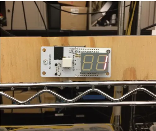
Pick-by-light is a method that utilised light cues to support order pickers (Vries, Koster, & Stam, 2016). Usually, pick and order bins are attached with a small LED display, push buttons and an LED light. When an item should be picked up from a certain location, the light would light up and the display would show the quantity that should be picked (see Figure 2.2). Then, pickers would press a button to indicate that they picked from the right location. Furthermore, another light would light up on the order bin to show pickers where the item(s) should be placed (see Figure 2.3). More advanced systems use sensors instead to detect picker’s hand movement when picking.
[image:15.595.172.424.423.634.2]15
Figure 2.3 – Instruction of where to place (P) the item (Guo et al., 2015).
Pick-by-Voice
Pick-by-voice is a common method used in warehouses. Order pickers are equipped with a headset that has a microphone (see Figure 2.4). They receive verbal instructions through the headset. Voice recognition is also used for e.g. confirming location, pick item and quantities. Previously conducted experiments show that, when compared with hand-held scanners, nearly all errors were eliminated when using this method (Dujmešić, Bajor, & Rožić, 2018). Moreover, the use of pick-by-voice increased the productivity of a warehouse by 70% which contributed to 20% improvement of the whole process (Dujmešić et al., 2018).
[image:16.595.196.401.429.631.2]16
Cart-Mounted Display (CMD)
As seen in Figure 2.5, pick-by-CMD is a method that “displays a graphical
representation of the picks on the order cart” (Guo et al., 2015, p.17). It seems that instrumenting the order cart is more effective and cheaper compared to instrumenting each shelves with pick-by-light systems.
[image:17.595.79.520.162.401.2]
Figure 2.5 – (Left) Cart-mounted display setup; (Right) Graphical representation of the cart (Guo et al., 2015).
Heads-Up Display (HUD)
HUDs are the same as head-mounted displays. In this method, the picker is equipped with a HUD that shows picking charts for each shelving unit (see Figure 2.6). After the picker drops items into the order bins, the HUD shows the next picking chart. The picking chart graphics shown in HUD is the same with CMD.
[image:17.595.94.512.548.695.2]17
Radio Frequency Scanning Devices
This technology uses handheld terminals that can scan barcodes and also provide real time data to pickers. This handheld terminal is also connected to the WMS. RF scanning devices have been used since 1980s, and has become the most widely used order picking technology due to its flexibility. Moreover, this technology can be used in different warehouse operations, not just order picking (“Order Picking Technologies | Voice | Pick Light | RF | MWPVL,” n.d.).
2.2 Augmented Reality
The definition of augmented reality (AR) is rather simple. Cirulis and Ginters (2013), Hanson, Falkenström, and Miettinen (2017) and Stoltz et al. (2017) define AR as the combination of the real world and virtual environment in real time. Whereas Azuma (1997) provides a more detailed and well-established definition of AR. He defines AR as systems that (i) operate interactively in real time, (ii) combine virtual and reality and (iii) integrate in 3D environment. In brief, AR is an interactive system that combines physical and virtual world in a 3D environment operating in real time.
Opportunities and Barriers
The future adoption of AR use in warehousing depends on several features. Stoltz et al. (2017) conducted an interview that resulted in seven important requirements from practitioners. The first requirement is related with user interface, which should be user friendly and easy-to-use with minimum interactions. Also, the use of the UI should not require special knowledge. Comfort is also an important requirement. Scanning activities should be quick and accurate. Moreover, the screen should be big enough to ease the reading of information. Battery is still a big technical concern of AR glasses, and consequently, practitioners would like no additional devices needed to be worn for the battery to last longer. Finally, the device should be robust and easy to programme. In general, most interviewees generally saw good potential in the use of AR in warehouses.
Furthermore, Stoltz et al. (2017) proposed potential benefits and barriers of using AR in warehouses. The use of AR in warehousing may reduce error rates, so re-picking may not be needed. The device can show the next steps thus limiting the need for decision makings. There is no need to remember what needs to be done because, again, the device will show it on the screen. So, in case the picker is disturbed, there would be no impact on the picking process. With image recognition, double checking can be done automatically. AR offers more flexibility, and possibly safety as they are hands-free.
18
2.3 State of the Art: Existing Use of AR in Order Picking
DHL Vision Picking2
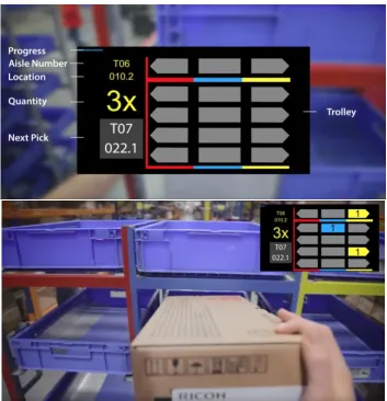
[image:19.595.140.494.259.626.2]Together with Ricoh and Ubimax, DHL successfully carried out a pilot project testing the use of smart glasses for batch picking. The pilot test was conducted in the Netherlands. Order pickers received task information through the graphics displayed on the screen (see Figure 2.7-Top). Figure 2.7 (Top) shows that the trolley is also displayed graphically. In Figure 2.7 (Bottom), it can be seen how the pickers received instructions on how many items should be put in which order bins. They claim to have resulted in a 25% increase in efficiency of order picking process (Hammerschmid, 2017). Furthermore, they received positive feedback from the pickers as they benefit from the hands free approach (Hammerschmid, 2017).
Figure 2.7 – (Top) Graphics display showing task information, including the trolley setup. (Bottom) The instruction of how many items should be put in which order bins.
19
Picavi3
[image:20.595.132.466.466.624.2]The system provides overview of important information in real time. It guides the picker to the right location, where they can scan the barcode to confirm the pick. Picavi is also constantly connected to the WMS or ERP (“Picavi - Pick-by-Vision - A new perspective on Intralogistics,” n.d.). This method was applied in a warehouse in Belgium, meaning that the system worked. However, the user interface (see Figure 2.8) does not look user-friendly, because there are too much letters there.
Figure 2.8 - Picavi user interface
Generix Group AR glasses4
The smart glasses connect pickers to the WMS by posting the information on the screen. This technology was used in an order picking process in a warehouse of a leading spare parts sales on the internet, Oscaro.com. As can be seen in Figure 2.9, the system guides the user to the correct location of the item, and then a small square shows up to show the item to be picked. The user interface looks simpler compared to the user interface by Picavi.
Figure 2.9 - User interface of smart glasses by Generix Group
20
Knapp - KiSoft Vision5
The system by Knapp navigates its users by using arrows and a distance meter shown directly in their field of vision. It also displays important information needed, such as a picture of the item that should be picked and also the quantity. The system also has a count feature that is automatically reduced whenever an item is picked
Figure 2.10 (Right). Compared to the others, the user interface seen in Figure 2.10
[image:21.595.84.514.190.346.2]also looks quite simple especially because it uses a visual-based approach.
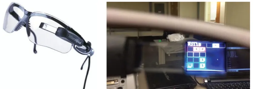
Figure 2.10 - (Left) Shows the device and location markers in the warehouse. (Right) Shows what the picker sees through the glasses
Summary of State of the Arts
The result of the state of the art research shows that the application of augmented reality in order picking is not new, as many technological companies have experimented with it. It was summarised that DHL’s Vision Picking is the most complete compared to the other systems. DHL’s Vision Picking focused on both informing the picker of the pick location and quantity, and guiding the picker on where to place the items they picked. While the other systems by Picavi, Generix Group and Knapp only focused on informing the picker of the pick location and quantity. In terms of user interface, Knapp and Generix Group are simpler compared to the others. Moreover, Knapp’s count feature is an interesting way of validating the amount of items picked.
2.4 Problem Statement
The research conducted on the application of augmented reality in batch picking process is quite limited. As mentioned before in section 2.1 about batch picking, pickers filled multiple orders simultaneously in one route. It was also mentioned that pickers have to carry a cart carrying multiple bins that are assigned for different orders, because they are picking by items instead of picking by order. This means that during the process of batch picking, pickers have to place the items they picked into the correct order bins. This is what is missing from most of the state of the arts found in section 2.3, the process of guiding pickers to the correct order bin and validating that pickers did place items in the correct order bin. The state of the arts found were mostly
21
applied in discrete order picking process. Hence, most of these state-of-the-arts focused on guiding pickers to the location of the items they have to pick and validating that the items pickers picked are correct. The aspects mentioned above regarding guiding and validating picker’s actions seem to be missing as well from the list of factors that affect order picking performance by Giannikas et al. (2017), Grosse et al. (2015) and Yu and de Koster (2009) in section 2.1.
DHL’s Vision Picking was applied in batch picking, since a cart with multiple bins can be seen in Figure 2.7 as well as the graphical representation of the cart on the screen. DHL’s Vision Picking is a perfect example for this project. The user interface is quite simple. However, they did not implement the process of validating the pickers on placing items in the correct order bin.
22
3 Methods and Techniques
3.1 Creative Technology Design Process
The ‘Design Process of Creative Technology’ (Mader & Eggink, 2014) is a method that is often used in graduation projects of Creative Technology students of University of Twente. Described in the literature, this design process consists of four phases; Ideation, Specification, Realisation and Evaluation. As can also be seen in the diagram, each of these phases are also described as an iterative process, meaning there is space for some reconsiderations of design choices or ideas.
In the Ideation Phase, early ideas are evaluated together with experts, clients or users. The way of working of the users should also be understood, hence the need for observations at the warehouse. This observation results in user stories that describe the current way of working of the users. An interview with the expert is also performed. Moreover, a stakeholder identification is performed to find out who the end users are. As described by Mader & Eggink (2014), the “result of the Ideation Phase is a (more) elaborated project idea, together with the problem requirements”, including ideas on experience and interaction.
The Specification Phase develop this result into a more solid concept. This phase includes an early prototyping phase to explore the design space. Then, experience and functional specifications are written based on the result of the observation in the Ideation Phase. This is followed by creating user scenarios that describe the use of augmented reality in picking processes.
During the Realisation Phase, an actual prototype is designed and built based on the requirements and specifications. The Realisation Phase includes designing the system and implementations of these ideas.
Following that is the final phase of the design process, the Evaluation Phase. It consists of several methods of evaluating the prototype built in the previous phase. Functional testing is an internal evaluation method which addresses the requirements made, and it could be performed in this phase. The more obvious way of evaluation is user testing, which will also be performed in this phase.
Last but not least, conclusions will be drawn based on the evaluations. Discussions will be discussed, followed with descriptions of future research.
3.2 Expert Interviews
23
3.3 Observations
Understanding the daily practice of the users is important. Information gathering comes in various ways. There are four general methods of collecting gathering information in research, such as individual interviews, focus groups, observations and action research (“3. Methods of collecting qualitative data,” n.d.). Observations were chosen to be conducted during the ideation phase. It was conducted to closely watch the process of batch picking, and have a taste of what actually happens in the process.
According to McLeod (2015), there are three observational methods that exist, controlled, naturalistic and participant observations. As the name suggests, controlled observations are usually structured. Meaning, all variables are regulated by the researcher, like where the observations take place, who the participants are, and in which circumstances. The procedure is standardised. This observation method fits best in a study where it is clear already which behaviours to observe (e.g. in a psychology lab).
Naturalistic method involves observing “spontaneous behaviour of participants in [their] natural surroundings.” (McLeod, 2015). This observation method is completely different than controlled observations. McLeod (2015) said that the difference between naturalistic and controlled observations is like “studying wild animals in a zoo and studying them in their natural habitat”. Naturalistic method enables researches to observe behaviour flow in its own area, or setting. Moreover, this method is frequently used to generate new ideas. However, the result of this method usually cannot be generalised in society since it is often conducted with only a small scale of participants, hence a lack in representative sample. Variables are unable to be controlled too, suggesting a lower reliability
Participant observation is a method where normally the researcher becomes part of the group that they are studying, joins in their daily activities in order to “get a deeper insight into their lives” (McLeod, 2015). This method can be overt or covert. Overt is when the researcher explains the research aim to the group and let them know they are being observed. While covert is when the method is carried out under cover, taking a false identity and role, much like the Undercover Boss show.
Given the explanations of each observation methods, the naturalistic method is the most suitable for this research. The controlled method is not suitable for this research since the observation is conducted at an early stage (Ideation Phase). Meanwhile, the participant observation is too time consuming. The naturalistic observation was conducted by, first, studying the environment, and then the whole process of batch picking.
3.4 PACT Scenarios
24
the Ideation Phase. PACT is a framework that prioritises the importance of people (users), activities, context and technology. A user story was written afterwards based on these four components.
3.5 Requirements & MoSCoW
Product requirements were written at the end of the Ideation Phase. It was written to determine which functionalities should be implemented in the final product, which in this case, is a prototype. These requirements were evaluated with an expert in the Evaluation Phase. An internal evaluation on these requirements was conducted as well.
Due to time constraints of this project, not all requirements can be applied in the prototype. The most important requirements were established first in order to have a prototype that meets the user’s needs. The MoSCow method was used to prioritise the requirements (Mulder, 2017). Ergo, all the requirements were categorised into four categories such as the Must haves, Should haves, Could haves, and Won’t haves. The
Must haves and Should haves were implemented in the prototype of this project.
3.6 Evaluation
Evaluation procedure was conducted to examine the requirements listed in the Ideation Phase. An evaluation with an expert was also performed. This evaluation process examined whether the prototype would be useful in picking processes in the future. The evaluation was conducted in two phases, functional testing and user testing.
Functional testing included an internal evaluation. The internal evaluation tested all MoSCoW requirements with the prototype. The evaluation with the end user or expert considered their expectations towards the prototype and whether the prototype met their expectations.
25
4 Ideation
4.1 Stakeholders
Research stakeholders
Gerben Hillebrand and CaptureTech Corporation BV are considered as major stakeholders of this research. The result of this research will benefit the company in a way that it helps them move a step further in their research on the use of AR in warehousing. Hillebrand contacted University of Twente, as a technical university, to give its students the chance to develop a solution for minimising errors in batch picking processes using AR. Even though the university is indirectly involved, it is considered as one of the stakeholders as well. It acts as a middle person, thus benefits from a positive research outcome. Although a negative research outcome may cause a negative image towards the university.
Product stakeholders
Regarding the end product (or prototype) of this research, the order pickers are considered as major stakeholders. They are the ones who will interact with the system and benefit from it. Companies would also benefit from this system, which would make them stakeholders too.
Potential Users
The project is initiated by Gerben Hillebrand to find out how AR can support the minimization of errors in batch picking processes. In this case, errors made by the order pickers. Hence, these order pickers are the main and only user group. The system is designed to assist them in batch picking tasks.
4.2 Observations
An observation was performed at the warehouse of IDEXX Europe B.V. The process of batch picking was the main focus of the observation. These observations included which method(s) was being used, how orders were assigned to the pickers, the process of batch picking itself (from beginning to the end), and the different kinds of errors that occurred.
4.2.1 General observation
26
Figure 4.1 – Picking cart carrying order bins
4.2.2 The Batch Picking Process
The batch picking process starts with the process of pairing the orders and bins. In this pairing process, pickers match the orders and bins by scanning the barcode of the orders and the bins using the handheld scanner. Orders and bins must be matched because the system needs to know which bin is assigned to which order.
27
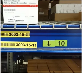
Figure 4.2 – An example of a special digit code is shown by the number ‘10’
Errors
There are two reasons why errors could happen, a bug in the software and human error. It is possible that sometimes the software is at fault. For instance, an error where the system provides order information that has already been picked. But, this is not the main focus of the project. The other reason, however, is the focus of the project. Human errors where pickers put the item(s) in the wrong bin, or when they put the item(s) with the wrong quantity, do happen quite often. Without physical confirmation, of which the current system does not have, it is difficult to prevent this error from happening.
Despite of that, with the system that the warehouse is currently using, the percentage of accuracy is already quite high. Even before they used voice recognition technology, the percentage of accuracy was more or less the same.
4.2.3 User Scenario
To make the observations at IDEXX Europe B.V. clearer, a user story was written. This user story described the way order pickers worked in the warehouse. The story was written using PACT method.
4.2.3.1 PACT Analysis
People: An order picker, 28 years old, working for two years at the warehouse.
Activities: Receive verbal instructions and perform batch picking processes in the warehouse.
28
Technology: The order picker uses a handheld scanner terminal to scan order lists and bin numbers, and a headset equipped with microphone and voice recognition to receive verbal instructions and mention code words.
4.2.3.2 Scenario
John has been working in the warehouse as an order picker for almost two years. His task is to listen and follow instructions of which order items to pick. It is 8:00 AM in the morning and he is about to start. He sees a picking cart with empty bins, and so he takes it with him. He goes to the printer to get 15 order lists since there are 15 bins on the picking cart. He put one order list on each bin. Using the handheld scanner terminal, he scans the barcode of the order list, then the barcode of the bin that it is in. He repeats this for the other 14 order lists and bins. These scanning activities are performed to assign an order list to a bin, and are recorded by the system.
After John completed all necessary scans, he is ready to begin the batch picking process. Through the mic of the headset, he mentions a code word telling the system that he is ready to receive pick instructions. Subsequently, he starts receiving pick instructions. Firstly, he receives a specific location in the warehouse where he needs to go. When John arrives, he mentions a check digit code shown on the shelf (see
Figure 4.2) to confirm that he is in the right location. Afterwards, he receives the pick quantity and the bin number. John needs to confirm both of these again too.
The batch picking process happens inside a giant freezer in the warehouse. The same process happens again. The difference is, this time he picks up several quantities of the same item that needs to be put in several different bins. In this process, he receives the bin number and the quantity. Then, John confirms it verbally, mentioning the quantity and the bin number.
4.2.4 Observation Conclusion
It can be concluded that errors occurred when pickers are placing the items into the order bins. Sometimes they place items into the wrong order bin, resulting in faulty picks. Even though pickers confirmed that they placed the item in the correct order bin, what happens is that what they confirmed to the system is different than what they actually do. Moreover, physical confirmation is also absent during the picking process. Only verbal confirmation is available.
Therefore, a more sophisticated guidance or warning system is needed to prevent such mistake from happening. On top of that, physical confirmation is also needed to make sure pickers did put the items they picked in the correct order bin.
4.3 Idea Generation
29
in which order bin the items should be placed. As a result, two concept ideas on how AR can be used as a guidance and a warning were generated and described below.
AR as a guidance
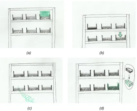
This concept idea focuses on providing a simple guidance to the user. This concept is based on the guidance feature from DHL’s Vision Picking, but it has a more direct approach by utilising virtual objects. The idea was to guide them to the right order bin after they received the order bin number. Several methods can be used for this idea. For example, using a simple green square in front of the right bin (see Figure 4.3a). A similar example is to use an animated 3D arrow pointing to the right order bin instead (see Figure 4.3b). A more complicated method would be to use a ‘tunnel’ that can change in length depending on how far the user is standing from the bin (see Figure 4.3c). Another interesting idea is to give the correct bin a new colour virtually, for instance, green (see Figure 4.3d).
(a) (b)
[image:30.595.73.527.285.651.2]
(c) (d)
Figure 4.3 – Several ideas of augmented reality as guidance
AR as a warning
30
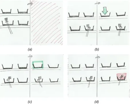
4.4d, a red square is shown when the hand of the user reaches the wrong bin. A second idea is to have a warning flash on the screen (see Figure 4.4a). A different approach for this AR as a warning feature is to have green messages of a 3D arrow or 2D square pop up in front of the correct order bin, only when the user’s hand is in front of the wrong bin (see Figure 4.4b and Figure 4.4c).
[image:31.595.72.527.153.516.2]
Figure 4.4 – Several ideas of augmented reality as warning
Item Count
As stated in section 4.2.4, physical confirmation is absent in the batch picking process. Physical confirmation is seen as a crucial addition to batch picking process, as it is able to confirm that pickers did place the item picked in the correct order bin. Thus, an item count can be used and shown on the screen. This item count represents the number of items that the user has to put in the order bin. The idea was to use hand tracking system that can track the user’s hand, and once it reaches the correct order bin and drops the item, the count is reduced.
Different coloured bins
The use of coloured bins could be an alternative way to reduce errors in batch picking. The instructions would use the different colours to differentiate each bin, as each bin would be given different colour codes. According to a discussion with the expert, this
(a) (b)
31
method is not preferred since there are fifteen bins carried by the picking cart. Using fifteen types of colours would be too much.
Use of RFID sensors
RFID sensors can be placed near the order bins and can be used to track the tags of the items for physical confirmation. The idea is to synchronise the sensors with the augmented reality system, acting as an external input. Assuming both systems can be linked, physical confirmation of the items can be performed. Even so, this method would be difficult to apply in this project due to limited time and knowledge on this topic. In addition, based on discussion with the expert, using sensors on the cart would mean that the picking cart is not flexible anymore. Meaning that when bins are removed and replaced with different sized bins, the sensors should be adjusted.
4.4 Requirements
The concept ideas were shown to an expert from the warehouse, and a couple of requirements were given. Although these requirements are a little bit vague. The augmented reality system to be applied in picking process is required to be robust and non-intrusive.
Since the requirements given are vague, more detailed requirements were created. This list determined what features should be implemented in the end prototype. Both functional and non-functional requirements were included in the lists below. The prioritisation of the requirements were executed following the MoSCoW method. Therefore, all requirements were categorised into one of the four categories: ‘Must haves’, ‘Should haves’, ‘Could haves’, ‘Won’t haves’.
No. Requirement Priority
R1.1 The system recognises the user’s environment and real world perspectives
Must
R1.2 The system recognises all markers Must
R2.1 The system provides AR guidance to the user Must R2.2 The system warns the user (with AR) when they are about to make
a mistake
Must
R3.1 The system instructs the user to scan order marker Should R3.2 The system instructs the user to scan bin marker Should R4.1 The system provides confirmation when order marker is scanned Should R4.2 The system provides confirmation when bin marker is scanned Should R4.3 The system provides confirmation of paired bins and orders Should R5.1 The system provides instructions to put a certain number of item(s)
into a certain order bin.
Should
R5.2 The user is able to reduce the item count Should R6. The system tracks hand movement of the pickers Could R7. The system is able to recognize bins with Object Recognition Could
Table 4.1 – Functional requirements
No. Requirement Priority
R1 The user interface should be clear and easy to understand Must R2 The system should recognise targets from a distance that pickers
normally stand
32
R3 The system should recognise targets in an instance Must
Table 4.2 – Non-functional requirements
4.5 Prototyping Phase
Prototyping was performed to explore the possibilities of augmented reality. The Vuforia engine software in Unity3D offers a reliable way of creating AR experiences. Using this engine software enables developers to create their own AR experience apps.
Early prototyping
A simple application of augmented reality as picking guidance was built early on during the project. This early prototype (see Figure 4.5) was able to detect image targets and overlay both static and animated 3D objects around it. The use of virtual buttons from the Vuforia library was also explored in this early prototype (the semi-transparent green square on the right). The original idea was to have an AR application that can track the movement of the user’s hand, but hand tracking is not yet possible with Vuforia. These virtual buttons were an alternative solution for this issue. When pressed, these virtual buttons will act as programmed. In this project’s case, the virtual buttons were used to activate the AR warning feature and reduce the item count.
[image:33.595.71.539.465.718.2]The prototype was built for androids since the AR glasses has an android operating system. The AR glasses used in this project is the Vuzix M300. Installing the AR application on the AR glasses was not easy at first. When connected to the computer, the Vuzix’s default setting for USB connection was to charge instead of file transfer. A third party software called Vysor was used to be able to control the AR glasses from the computer and change the settings.
33
Testing of different marker sizes
Different sizes of markers were tested during this prototyping phase. These markers refer to image targets that are placed in a scene to provide a fixed point of reference for a virtual object. The tests were performed in order to see which marker size works best relative to the standing distance of the users from the markers. The process of batch picking happened very quickly, so markers should be detected in an instant and from a certain distance.
Object Recognition
Vuforia’s Object Recognition allows developers to build apps that can recognise and track objects, as opposed to markers. However, this feature has been designed to work best with toys that are opaque, rigid, contain few moving parts and have contrast-based features on the surface6. Even though the bins used are actually opaque and rigid,
their shape is too simple to be detected and these bins only have one colour. Additionally, Vuforia’s object recognition is only capable of scanning small objects. On top of that, the object scanner is only for Samsung Galaxy S5 and Google Nexus 5. So, object recognition cannot be easily implemented right now.
Vumarks and Extended Tracking
Vumark (Vuforia Marker) is a next generation bar code developed by Vuforia that is meant to be used in enterprises and consumer markets. The design of Vumark is completely customisable, thus provides a “universal solution for delivering unique augmented reality experiences on any object”7. Vumarks are able to present millions
of instances that are unique. Moreover, it can store a variety of data formats. The application of it was not easy though. Unfortunately, Vumarks could not be applied yet due to technical issues regarding the Vuforia software and Unity version used. So, it was decided to use basic QR codes first for now.
Extended tracking is a Vuforia feature that enables augmented reality applications to allow augmentations (or virtual objects) maintain their virtual positions with respect to the real world. In other words, augmentations that are attached to the image targets will persist when users point the device away from initial point. Unfortunately, extended tracking could not be implemented due to software issues. It was discovered that newer versions of Unity3D and Vuforia does not work well with extended tracking system.
4.6 Prototype Idea
In section 4.3, several concept ideas were generated as a solution. It was decided to implement Figure 4.3a and Figure 4.3b as the augmented reality guidance features of the prototype. Additionally, it was also decided to implement Figure 4.4a and Figure 4.4d as the AR warning features of the prototype. These features were chosen to keep the prototype simple, since it was stated in the non-functional requirement R1 that the user interface has to be clear and easy to understand. Last but not least, the item count was included in the prototype as well. However, since hand tracking is not supported
34
[image:35.595.91.508.104.422.2]by Vuforia, the item count is reduced by pressing the virtual button placed in front of the bin markers. An example of how the prototype looks can be seen in Figure 4.6.
Figure 4.6 – Example of how the prototype looks.
5 Specification
The main goal of the prototype is two-fold, and is related to the process of putting picked items into the order bins. Firstly, the prototype is capable of guiding the user to the correct order bin. Secondly, warn the user if they are about to make a mistake of putting an item into the wrong order bin. In addition, the prototype is also capable of simulating the process of pairing the order list and the order bin. This means the prototype is divided into two parts, the pairing process and the process of guiding or warning the user.
5.1 Prototype Description
The prototype is capable of recognising markers from a certain distance at which order pickers are normally standing. Moreover, the prototype is able to recognise markers in an instance.
35
The user interface of the two parts of the prototype are different. In the beginning, the user receives an instruction to scan the order marker, followed by an instruction to scan the bin marker. Moreover, once the markers have been scanned, the symbols change colour. These symbols are shown on the centre of the screen. When both markers are scanned, a pair confirmation is shown on the left side of the screen. This ends the user interface for the first part of the prototype.
As for the second part of the prototype, the user interface begins with a message of ‘No Tote Found’ shown on the bottom right of the screen. This message will change to ‘TOTE FOUND’ if a bin marker is visible in the glasses’ field of view and recognised by the system. Furthermore, when the user receives an instruction to put a number of items into an order bin, the quantity is shown on the right side of the screen. The user is able to reduce the item count by putting their hand in front of the correct order bin, covering the marker attached to the bin. After the count has been completed (reaches zero), a check symbol for confirmation is shown at the same spot on the screen.
Regarding the main AR features, the prototype is able to provide augmented reality guidance for the users towards the correct order bin as well as warn the users if they are about to make a mistake. For the AR guidance system, the prototype is able to show two methods, using a 3D arrow and a green square. For the AR warning system, the prototype is able to provide feedback when a user makes a mistake. There are two methods for this, using a flash on the screen and a red square.
5.2 User Scenario
This user scenario was written based on the augmented reality ideas generated in the Ideation Phase and the prototype specification described above. It focuses on how these AR ideas can be applied in picking process. It is important to note that if eventually AR is going to be used in picking process, it will be combined with the voice recognition software. This means that instructions on pick locations and quantity will be given verbally through the headset. The scenario features the use of AR as guidance and warning, as well as for order and bin pairing purposes.
PACT Analysis
People: An order picker, 25 years old, working for three years at the warehouse.
Activities: Receive visual and verbal instructions, and perform batch picking process in the warehouse.
Context: Batch picking process at the warehouse of IDEXX Europe B.V.
Technology: The order picker is equipped with augmented reality glasses that enables them to see real time feed through the camera of the device and augmented reality objects.
Scenario
36
reality glasses and the headset. Then, she takes a cart with empty order bins. She goes to the printer to get the order lists. She took 15 papers, since there are 15 bins on the picking cart. She puts one order list in each bin. The batch picking process starts with pairing process of the orders and bins. The AR software starts and immediately she sees an instruction to scan the order lists. Using the AR glasses, she scans the marker of an order list. She receives a confirmation message that an order list has been scanned. Then, she receives an instruction to scan the bin marker. She follows this instruction, and receives another confirmation message that the bin marker has been scanned. She also receives a confirmation that the first order list and the first bin has been paired successfully. She repeats this process for the other 14 order lists and bins.
After Yvonne has completed all necessary scans for the pairing process, she begins the batch picking process. She receives pick locations through the headset. When she arrives at the pick location, she mentions the check digit code to confirm that she is at the right location. Then, she receives verbal instruction for the pick quantity. She picks the item(s) and confirms the quantity again. Then it is time for her to place the item in the correct order bin. When she faces towards the cart, the AR guidance feature shows her where she should place the item. Each time she places the picked item in the correct bin, the system confirms it by reducing the count (one by one) shown on the screen. When the count reaches zero, she receives a check symbol confirming that the count for that order bin is completed. She receives the next instructions and continues the batch picking process. At some point, she is about to put an item in the wrong order bin. The AR warning feature automatically activates to remind her. Since the warning comes at the right time, she corrects her mistake right away.
6 Realisation
Now that specifications were already discussed, the system was designed based on them along with the implementations. Several iterations including intermediate tests were also conducted in the implementations phase.
6.1 System Design
6.1.1 User Interaction
37
Figure 6.1 – Use Case Diagram
6.1.2 System Breakdown
Using black boxes is a way to design a system and its parts. Every black box has an input and an output. These black boxes are drawn from the highest level of the system, meaning a black box that represents the whole system, to the lower levels (or parts) of the system. This indicates that the black boxes will become more detailed.
As seen in Figure 6.2, the entire system is represented by a black box. One user interacts with the system. All user inputs that are previously listed in the use case diagram (Figure 6.2) are generalized as “user interaction”. The user receives a single
output from the system, which is the real time camera view consisting augmented reality objects.
Figure 6.2 – Input and output of the entire system
System
38
Figure 6.3 – Main components of the system running in Vuzix M300
Augmented Reality Application
The augmented reality application consists of three components, the application core, augmented reality tracking and the user interface (see Figure 6.4). The application core communicates with the operating system of the device. Thus, all incoming and outgoing communications of the AR application should go through the application core. The AR app itself was created in Unity3D using Vuforia engine software. Vuforia is an external software that provides a platform, which enables developers to create an AR application.
39
Figure 6.4 – Three main components of the AR application
Augmented Reality Tracking
It can be seen in Figure 6.5 what the functionalities of augmented reality tracking are. This component is responsible for accessing the 3D world from the camera feed and track AR markers and virtual buttons. This component generates new world coordinates which can be used to align the virtual world to the real world. Subsequently, virtual objects can be shown around the user. Since this component is responsible for tracking AR markers and virtual buttons, it will send confirmation to the user interface when they are recognised in the camera feed.
Figure 6.5 – Functionalities of augmented reality tracking
User Interface
40
41
6.2 Implementations
6.2.1 Augmented Reality Tracking
Markers
In theory, it would be ideal to have a software that is able to recognize and scan 3D perspectives of the bins. However, it is not possible to scan real world objects using the Vuforia library. On top of that, scanning 3D objects is not easy. Thus, making it unreliable. A solution is to use markers that are attached around the working environment e.g. in front of the bins. These markers are image targets that the system tracks in order to perform specific tasks. Image targets used in this project were downloaded from an online AR marker generator8.
Figure 6.7 – Image targets
Vuforia Virtual Buttons
To be able to activate the warning feature and reduce the item count, virtual buttons from Vuforia are used. These virtual buttons are set on top of the image targets (as seen in Figure 6.8). Therefore, when the user’s hand blocks the marker, they are
actually pressing this virtual button. When the system tracks that the virtual button has been pressed, it is programmed to do two things, activate the augmented reality warning feature and reduce the item count. Even though the virtual buttons have a colour (light blue), they are actually set to be invisible to create a sense of automation. In other words, to make users think that the system is tracking their hand instead of pressing a button.
42
Figure 6.8 – Vuforia virtual buttons shown by the light blue colour
Augmentations
[image:43.595.176.421.69.270.2]The augmented reality as guidance system features two kinds of virtual objects. One is using a 3D arrow pointing downwards towards the bin (see Figure 6.9). The other is using a 2D green square hovering in front of the bin (see Figure 6.10).
43
Figure 6.10 – Augmented reality guidance featuring 2D square
There are two ideas for the AR warning feature. The first idea features a 2D red square hovering in front of the bin (see Figure 6.11). Another one features a red flash on the screen (see Figure 6.12). These warning features are programmed to be activated only when the user’s hand is in front of the bin, basically representing that they are about to make a mistake.
[image:44.595.75.527.441.696.2]44
Figure 6.12 – Visualization of another augmented reality warning feature
6.2.2 User Interface
As stated in the non-functional requirement R1, the user interface should be clear and user-friendly. Thus, users should not require extra knowledge in order to use it. Therefore, it has been chosen to use mainly visuals as the basis of the interface. This is based on the background research on requirements for the application of augmented reality in warehouse operations.
Visual Messages
There are several visual messages sent to the user by the system. Since the batch picking process starts by the pairing process of the orders and bins, it was decided to have visual messages for this process. Firstly, these visual messages include instructions to scan the marker of the order (see Figure 6.13) and bins (see Figure 6.14). Secondly, the visual messages include confirmations of when an order marker has been scanned (see Figure 6.15) and when the bin marker has been scanned (see
45
[image:46.595.120.478.306.580.2]Figure 6.13 – Instruction to scan order marker
Figure 6.14 – Instruction to scan bin marker
[image:46.595.121.477.435.722.2]46
Figure 6.16 – Confirmation message when bin marker is scanned, along with the paired confirmation
Count Digit
The user interface of this item count is simple, just digit on the screen (see Figure 6.17). This count is located at the right side of the screen. The user interface also gives feedback on the status of the count to the user. Firstly, the count reduces when the user put their hand in front of the correct order bin. Secondly, when the count reaches zero, a check symbol is shown. This can be seen in Figure 6.18.
[image:47.595.124.478.419.619.2]47
Figure 6.18 – Count completed confirmation
6.2.3 Intermediate Tests
Intermediate tests were performed with users outside the target group in order to see whether they were able to reduce the item count by pressing the virtual button. The tests were performed without telling them that virtual buttons are available. The result of this test was that sometimes users were attracted to the 3D arrow that is located above the marker, thus moving the camera view a little bit upwards. Consequently, virtual buttons were not fully tracked. As a solution, it was decided to use four 3D arrows instead (seen in Figure 6.19) and make them point to the centre of the marker. This way it was hoped that the user’s attention would be attracted more to where the points meet, the centre of the marker.
[image:48.595.75.527.466.722.2]48
Another solution was to add messages of when the bin marker is being tracked or lost. The same goes for the virtual buttons. However, it was decided to add confirmation messages for the bin marker first (as seen in Figure 6.20) because the virtual buttons are placed in front of the markers.
Figure 6.20 – Confirmation for bins tracked and lost
Possibility of audio confirmation
49
7 Evaluation
7.1 Functional Testing
The functional requirements were evaluated internally, meaning by the researcher itself. The aim of this evaluation was to see whether the important functionalities, listed in the Ideation Phase, were implemented in the prototype. All requirements were listed in table 7.1 along with an indicator whether the requirements were met by the prototype.
No. Requirement Priority Achieved
R1.1 The system recognises the user’s environment and real world perspectives
Must Yes
R1.2 The system recognises all markers Must Yes R2.1 The system provides AR guidance to the user Must Yes R2.2 The system warns the user (with AR) when they are
about to make a mistake
Must Yes
R3.1 The system instructs the user to scan order marker Should Yes R3.2 The system instructs the user to scan bin marker Should Yes R4.1 The system provides confirmation when order marker
is scanned
Should Yes
R4.2 The system provides confirmation when bin marker is scanned
Should Yes
R4.3 The system provides confirmation of paired bins and orders
Should Yes
R5.1 The system provides instructions to put a certain number of item(s) into a certain order bin.
Should Yes
R5.2 The user is able to reduce the item count Should Yes R6. The system tracks hand movement of the pickers Could No R7. The system is able to recognise bins with Object
Recognition
Could No
Table 7.1 – Internal evaluation of prototype requirements
From the results of the evaluation in table 7.1, it was concluded that all ‘Must have’ requirements were all implemented in the prototype. This means that the basic features of the prototype, such as the augmented reality guidance and warning features, worked. The ‘Could have’ requirements were not implemented in the prototype. R6 was not implemented in the prototype because it was not supported by the Vuforia software. While R7 was not implemented because even though object recognition is supported by Vuforia, it was developed only for small objects (e.g. mini toys) that have multiple colours. On top of that, the object scanner application could only be used in limited devices as stated in section 4.6. Both R6 and R7 should be researched further in the future.