Effect of Temperature and Strain Amplitude on Dislocation Structure
of M963 Superalloy during High-Temperature Low Cycle Fatigue
Lizi He
1;2;*, Qi Zheng
1, Xiaofeng Sun
1, Hengrong Guan
1, Zhuangqi Hu
1,
Kiet Tieu
2, Cheng Lu
2and Hongtao Zhu
21Department of Superalloys, Institute of Metal Research, Chinese Academy of Sciences, Shenyang 110016, P. R. China 2School of Mechanical, Materials and Mechatronics Engineering, University of Wollongong, Wollongong, NSW 2522, Australia
An investigation was made on the strain-controlled low cycle fatigue (LCF) of a cast Ni-base superalloy M963 over a wide total strain range of 0.15–0.6% at a temperature range from 700 to 950C in air. Correlations between dislocation structure and the testing temperature and
applied strain amplitude were enabled through transmission electron microscopy (TEM) observation. At a low temperature region (700 and 800C), dislocation shearing0precipitates by dislocation pairs and stacking faults at medium and high strain amplitudes, and a well-defined
dislocation network at low total strain amplitudes were evident. At a high temperature region (900 and 950C), dislocations by-passing0
precipitates was the main deformation mode.
(Received June 28, 2005; Accepted November 2, 2005; Published January 15, 2006)
Keywords: M963 superalloy, low cycle fatigue (LCF), temperature, strain amplitude; dislocation structure
1. Introduction
Ni-base superalloys have performed well as turbine blade and disc materials due to their excellent mechanical and corrosion resistance properties at high temperatures. Since these components are always subjected to repeated thermal stresses, high temperature low cycle fatigue failure is the major factor affecting the service life of the turbine blades. Extensive works have been done on some superalloys in order to reveal the relationship between the cyclic frequen-cy,1–4) stain rate,5–8) waveform,9) strain range,10–12) hold
period,13–16) predeformation,17,18) environment4,19–21) and
temperature7,22–25)on the cyclic stress response, deformation
mode and fatigue life during high temperature low cyclic fatigue. It can be realized that the temperature- and time-dependent processes may often be associated with a substantial reduction in the fatigue life because of increasing temperature, decreasing cyclic frequency, or the introduction of hold period and predeformation.
M963, a cast polycrystalline Ni-base superalloy, is being used for blades and vanes in gas turbine engines. It has a chemical composition and microstructures similar to those of Ni-base superalloy Mar-M200. Due to its relative high contents of refractory elements such as tungsten, molybde-num, titanium and niobium,etc., it has been reported that the alloy has intermediate temperature brittleness,26) and some
efforts have been made to improve this behavior.27–29)
Carbide precipitation behaviors during high-temperature creep and low-cycle fatigue tests have also been dis-cussed.30,31)Investigating the low cycle fatigue deformation
mechanism would be beneficial in the development of high-temperature alloys, to achieve more resistant alloys and to rationalize the low cycle fatigue behavior of these alloys. Up to now, the high-temperature low cycle fatigue properties of M963 superalloy have not been published. In this paper, total strain controlled low cycle fatigue tests have been conducted in a temperature range from 700 to 950C, to understand the
influence of temperature and strain amplitude on low cycle fatigue behavior of M963 superalloy.
2. Materials and Experimental Procedures
The chemical composition of M963 master superalloy used in this work is listed in Table 1. Minor elements are 8 mass ppm P, 10 mass ppm S, 3 mass ppm O and 6 mass ppm N. The master alloy was remelted and cast into test bars, which were solution treated at 1210C for 4 h and followed by air cooling. The solution treated microstructure consists of
matrix, 0 precipitate, þ0 eutectic, MC and M 6C carbides. The0particles at dendritic regions have an average size of 0.4mmand volume fraction of 42% approximately.
Low cycle fatigue specimens were machined from solution treated bars with a l5 mm diameter and a 25 mm gauge length. All test specimens were ground along the gage length in the longitudinal direction with SiC paper down to grit 1200 in order to minimize the influence of surface defects on test results. Before testing, nondestructive evaluation was used to check for casting pores in the specimens. A servohydraulic testing machine was used to perform the fatigue tests at 700– 950C in air. The total axial strain was measured and controlled by an extensometer mounted on the specimens. The total strain range varied from 0:15 to0:6% with a fully reversed strain-controlled push-pull mode,i.e.,R¼ 1. The strain rate was 4103s1, applied in a triangular waveform. The temperature fluctuation over the gage length area was maintained within2C. All specimens were run to failure. Three specimens were prepared for each strain amplitude.
Samples for transmission electron microscopy (TEM) were performed on Philips EM420, obtained from a thin slice
Table 1 The chemical composition of M963 alloy (mass%).
C Cr Al Ti Mo W Co Nb Zr B Ce Y Ni
0.15 8.89 6.00 2.55 1.64 10.10 10.01 1.10 0.031 0.03 0.02 0.01 Bal.
(200mm) cut at a distance of 5 mm away from the fracture surfaces of the failed specimens. Thin foils were prepared by twin-jet thinning electrolytically in a solution of 7% perchloric acid and 93% alcohol at30C, 40 mA.
3. Results and Discussion
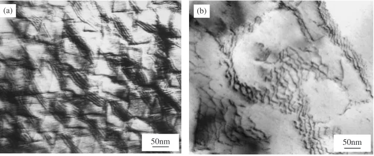
Typical dislocation structures after LCF testing at 700C are shown in Fig. 1. When a strain amplitude is as high as 0.6%, the fatigue life is very short, and 36 cycles were achieved. High density dislocation pairs are trapped in narrow planar slip bands (marked by arrow), which cut through0precipitates, and deformation is very
inhomoge-neous [Fig. 1(a)]. At a medium strain amplitude ("t=2¼
0:4%), deformation is still inhomogeneous, and high density stacking faults are found in narrow planar slip bands (shown by arrows). Most stacking faults travel across several 0 precipitates [Fig. 1(b)]. At a low strain amplitude ("t=2¼
0:25%), 0 precipitates are free of dislocations, and a dislocation network is evident. It can also be noted that 0 precipitate have lost its cubic shape at such low strain amplitude [Fig. 1(c)].
Dislocation structures for specimens after LCF testing at 800C are presented in Fig. 2. When a strain amplitude is 0.5% [Fig. 2(a)], many stacking faults which are located in planar slip bands cut0precipitates at a angle of 45, and the
50nm (c)
100nm (a)
50nm (b)
Fig. 1 TEM images showing the dislocation structures after low cycle fatigue testing at 700C. (a)"
t=2¼0:6%Nf¼36cycles,
(b)"t=2¼0:4%Nf¼2:5103cycles, (c)"t=2¼0:25%Nf¼5:4104cycles.g¼ f001g.
50nm (b)
(a)
50nm
Fig. 2 TEM images showing the dislocation structures after low cycle fatigue testing at 800C. (a)"
t=2¼0:5%Nf¼204cycles,
[image:2.595.114.483.73.368.2] [image:2.595.116.482.424.577.2]density of slip bands is higher than that at 700C and
"t=2¼0:4% [Fig. 1(b)]. At a low strain amplitude
("t=2¼0:25%), a more homogeneous dislocation network
is also formed (Fig. 2(b)).
Figure 3 illustrates the typical dislocation structures after LCF testing at 900C. In Fig. 3(a), many dislocations are curved, indicating that they have bowed between the coarse
0precipitates. At some regions, the dislocations are some-what waved (marked by double arrow), demonstrating that dislocations are passing through0precipitates by cross slip. In Fig. 3(b), high density tangled dislocations located in
channels can be observed. However, it should be noted that
the dislocations in local regions have a tendency to form a dislocation network.
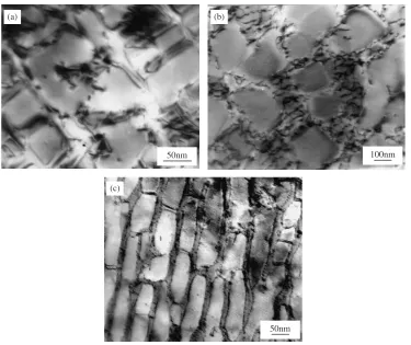
[image:3.595.113.482.70.227.2] [image:3.595.112.487.273.588.2]Figure 4 shows the typical dislocation structures after LCF testing at 950C. It can be seen that dislocation density for a strain amplitude of 0.4% is much lower than that at lower temperatures [Figs. 1(a) and 2(a)], and tangled dislocations distributed in channels at some regions are also observed [Fig. 4(a)]. When the strain amplitude is 0.2%, a homoge-neous dislocation network is formed in channels [Fig. 4(b)]. At a lower strain amplitude of 0.15%, a well-defined=0interface dislocation network is formed, and0
precipitates have completely rafted [Fig. 4(c)].
50nm (a)
50nm (b)
Fig. 3 TEM images showing the dislocation structures after low cycle fatigue testing at 900C. (a)"
t=2¼0:3%Nf¼1:3103cycles,
(b)"t=2¼0:2%Nf¼3:1104cycles.g¼ f001g.
(c)
50nm (b)
100nm 50nm
(a)
Fig. 4 TEM images showing the dislocation structures after low cycle fatigue testing at 950C. (a)"
t=2¼0:4%Nf¼284cycles,
According to above observations, it can be concluded that the main deformation mode of M963 superalloy during high-temperature LCF is planar slip and can be divided into two groups: low temperature region (700 and 800C) and high temperature region (900 and 950C). The influence of temperature on dislocation characteristics in LCF is much like that in a high temperature tensile test,28)however, it is
also closely related with applied strain amplitude.
At the low temperature region and medium and high strain amplitudes, 0 precipitates are cut by dislocation pairs and stacking faults due to a relatively fine0size. Deformation is inhomogenous and is trapped in slip bands which causes a much reduced fatigue life of the alloy. At a low strain amplitude, the fatigue life is long enough that the creep effect becomes significant, dislocations travel coarse0precipitates by climbing and cross slip more easily, and thus a well-defined dislocation network is formed. In present work, it is not possible to analyze the partial dislocation which creates the extended stacking faults, since the faults are so large, and the leading and trailing partials are never both within the usable thin area of a foil. Standard dark-field imaging is used on the extended faults, however, and they are found to be always intrinsic in nature, confirming that they are super-latice intrinsic stacking-faults (SISFs). Leverant and Kear32)
proposed a mechanism involving SISF/superlattice extrinsic stacking-faults pairs and a combination of differenta=2h110i dislocations at the interface. Recent researchers33–35) found that the most likely reaction seemed to be the decomposition of ana=2h110idislocation through following reactions:
a
2½101 !
a
6½12211 þ
a
3½112
which did not recombine on exiting the particles. Additional effects of the presence of the fault and the partial dislocations which caused them were likely to exist. For example, Milligan and Antolovich35)suggested that the unique
behav-ior of PWA1480 single crystals, which exhibit a 20% reduction in strength from room temperature to 400C, correlated exactly with the temperature dependence of an SISF-based mechanism. M963 alloy is also observed to have a reduction in LCF strength from room temperature to 900C.36)This is due to the connected slip bands which make
plastic deformation proceed inhomogeneously by formation of deformation bands.
At the high temperature region (900 and 950C), disloca-tions by-passing 0 precipitates is the main deformation mode. At a high strain amplitude, deformation is inhomoge-neous, and high density of tangled matrix dislocations pile up at=0interface in order to push the leading dislocations to pass the 0 precipitates by bowing or cross slip. At a low strain amplitude, deformation is homogeneous, and a well-defined dislocation cellular structure or network is evident. The creep effect is very significant at 950C, the density of dislocation is lower even for a high strain amplitude of 0.4%, and the formation of dislocation networks speeds up. At high temperature, the diffusion-controlled processes are more apparent, dislocations are more mobile by the mechanism of climb and cross slip, and additional slip systems are introduced with increasing temperature. Hence, thermally activated motion of the dislocations results in a
rearrange-ment to a cell wall structure. The increasing effect of thermal recovery with increasing temperature causes a change from disordered cell into ordered=0network.
The planar slip and dislocation cellular structure have also been observed by other researchers.37–39) Sirnivasa et al.37)
found that nitrogen promoted the planar slip and a tendency for cell formation at lower stain rates at 600C in the LCF behavior of 316L(N) stainless steel. El-Madhoun et al.38)
discovered that the dislocation cellular structure was the predominant dislocation structure at the strain range of
1:0103–1:1102 due to high stacking energy of polycrystalline aluminum. Mutual trapping of mobile dis-locations into bundles and subsequent development into dislocation networks were attributed to the operating hard-ening mechanism. Fournier and Pineau39) found that 00
precipitates were sheared by partial dislocations, which could promote deformation by twinning in LCF behavior of Inconel718 at room temperature and 550C.
4. Conclusion
The deformation mode during high-temperature low cycle fatigue is predominant planar slip and can be divided into two groups: low temperature region (700 and 800C) and high temperature region (900 and 950C). At a lower temperature region (700 and 800C), dislocations cutting0precipitates by dislocation pairs and stacking faults trapped in inhomo-geneous distributed slip bands at medium and high strain amplitudes which cause the reduction in LCF strength, a well-defined dislocation network is observed at low strain amplitudes. At a higher temperature region (900 and 950C), dislocations by-passing 0precipitates is the main deforma-tion mode. The tangled dislocadeforma-tions distribute in channels at high strain amplitudes. Formation of dislocation network speeds up at low strain amplitudes.
REFERENCES
1) A. Shyam and W. W. Milligan: Acta Mater.52(2004) 1503–1513. 2) P. K. Liaw, H. Wang, L. Jiang, B. Yang, J. Y. Huang, R. C. Kuo and
J. G. Huang: Scr. Mater.42(2000) 389–395. 3) Y. L. Wang: Int. J. Fatigue19(1997) 345–350.
4) M. Reger and L. Remy: Mater. Sci. Eng. A101(1988) 55–63. 5) Z. F. Yue and Z. Z. Lu: Metall. Mater. Trans. A29A(1998) 1093–
1099.
6) F. Jiao, D. Bettge, W. Osterle and J. Ziebs: Acta Mater.44(1996) 3933–3942.
7) E. Vasseur and L. Remy: Mater. Sci. Eng. A185(1994) 1–15. 8) M. Valsan, D. H. Sastry, K. B. S. Rao and S. L. Mannan: Metall. Mater.
Trans. A25A(1994) 159–171.
9) K. Kakehi: J. Jpn. Inst. Met.62(1998) 653–661. 10) B. S. Rho and S. W. Nam: Mater. Lett.48(2001) 49–55.
11) A. Bhattacharyya, G. V. S. Sastry and V. V. Kutumbarao: J. Mater. Sci. 34(1999) 587–591.
12) J. Auerswald, D. Mukherji and W. Y. Chen: Z. Metall.88(1997) 652– 658.
13) N. Isobe and S. Sakurai: Mater. Sci. Res. Int.9(2003) 29–33. 14) L. J. Chen, P. K. Liaw, Y. H. He, M. L. Benson, J. W. Blust, P. F.
Browing, R. R. Seeley and D. L. Klarstrom: Scr. Mater.44(2001) 859– 865.
15) R. Joos and E. Arzt: Z. Metall.89(1998) 653–660.
16) L. J. Chen, G. Yao, J. F. Tian, Z. G. Wang and H. Y. Zhao: Int. J. Fatigue20(1998) 543–548.
277.
18) M. Sundararaman, W. Chen and R. P. Wahi: Scr. Metall. Mater.30 (1994) 1207–1211.
19) M. Marchionni, G. A. Osinkolu and G. Onofrio: Int. J. Fatigue24 (2002) 1261–1267.
20) E. Aghion, M. Bamberger and A. Berkovits: Mater. Sci. Eng. A147 (1991) 181–189.
21) M. Dollar, I. M. Bernstein, A. Domnanovitch, W. Kromp and H. Pinczolits: Metall. Trans. A22A(1991) 2597–2603.
22) B. S. Rho, S. W. Nam and X. Xie: J. Mater. Sci.37(2002) 203–209. 23) K. B. S. Rao, M. G. Castelli, G. P. Allen and J. R. Ellis: Metall. Mater.
Trans. A28A(1997) 347–361.
24) A. Hynna, V. T. Kuokkala, J. Laurila and P. Kettunen: J. Mater. Eng. Perf.2(1993) 531–536.
25) M. Reger and L. Remy: Mater. Sci. Eng. A101(1988) 47–54. 26) C. Yuan, X. F. Sun, F. S. Yin, H. R. Guan, Z. Q. Hu, Q. Zheng and
Y. Yu: J. Mater. Sci. Technol.17(2001) 425–428.
27) F. S. Yin, X. F. Sun, J. G. Li, H. R. Guan and Z. Q. Hu: Scr. Mater.48 (2003) 425–429.
28) L. Z. He, Q. Zheng, X. F. Sun, G. C. Hou, H. R. Guan and Z. Q. Hu:
Mater. Sci. Eng. A380(2004) 340–348.
29) L. Z. He, Q. Zheng, X. F. Sun, H. R. Guan, Z. Q. Hu, A. K. Tieu, C. Lu and H. T. Zhu: Mater. Sci. Eng. A398(2005) 128–136.
30) L. Z. He, Q. Zheng, X. F. Sun, H. R. Guan, Z. Q. Hu, A. K. Tieu, C. Lu and H. T. Zhu: Mater. Sci. Eng. A397(2005) 297–304.
31) L. Z. He, Q. Zheng, X. F. Sun, H. R. Guan, Z. Q. Hu, A. K. Tieu, C. Lu and H. T. Zhu: J. Mater. Sci.40(2005) 2959–2964.
32) G. R. Leverant and B. H. Kear: Metall. Trans. A1A(1970) 491–498. 33) R. Bonnet and A. Ati: Acta Metall.37(1989) 2153–2169.
34) P. R. Bhowal, E. F. Wright and E. L. Raymond: Metall. Trans. A21A (1990) 1709–1717.
35) W. W. Milligan and S. D. Antolovich: Metall. Trans. A22A(1991) 2309–2318.
36) L. Z. He, Q. Zheng, X. F. Sun, H. R. Guan, Z. Q. Hu, A. K. Tieu, C. Lu and H. T. Zhu: Mater. Sci. Eng. A402(2005) 33–41.
37) V. S. Srinivasan, M. Valsan, R. Sandhya, K. B. S. Rao, S. L. Mannan and D. H. Sastry: Inter. J. Fatigue21(1999) 11–21.
38) Y. El-Madhoun, A. Mohamed and M. N. Bassim: Mater. Sci. Eng. A 359(2003) 220–227.